Page 1653 of 5135
05AF5±02
B67412
Unlock Warning Switch Assy
Front Door Courtesy Lamp Switch Assy
�Integration Relay
Combination Meter Assy
Instrument Panel J/B Assy�Warning Buzzer
Instrument panel J/B Assy
Unlock Warning Switch Assy
Front Door Courtesy Lamp Switch AssyCombination Meter Assy
�Warning Buzzer
RHD ModelsLHD Models
�Integration Relay
Center J/B
05±1590
± DIAGNOSTICSKEY REMINDER WARNING SYSTEM
AVENSIS REPAIR MANUAL (RM1018E)
LOCATION
Page 1654 of 5135
05AF0±02
± DIAGNOSTICSKEY REMINDER WARNING SYSTEM
05±1589
AVENSIS REPAIR MANUAL (RM1018E)
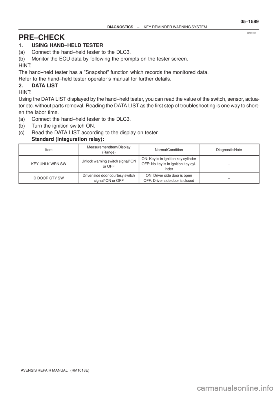
PRE±CHECK
1. USING HAND±HELD TESTER
(a) Connect the hand±held tester to the DLC3.
(b) Monitor the ECU data by following the prompts on the tester screen.
HINT:
The hand±held tester has a ºSnapshotº function which records the monitored data.
Refer to the hand±held tester operator's manual for further details.
2. DATA LIST
HINT:
Using the DATA LIST displayed by the hand±held tester, you can read the value of the switch, sensor, actua-
tor etc. without parts removal. Reading the DATA LIST as the first step of troubleshooting is one way to short-
en the labor time.
(a) Connect the hand±held tester to the DLC3.
(b) Turn the ignition switch ON.
(c) Read the DATA LIST according to the display on tester.
Standard (Integuration relay):
ItemMeasurement Item/Display
(Range)Normal ConditionDiagnostic Note
KEY UNLK WRN SWUnlock warning switch signal/ ON
or OFFON: Key is in ignition key cylinder
OFF: No key is in ignition key cyl-
inder
±
D DOOR CTY SWDriver side door courtesy switch
signal/ ON or OFFON: Driver side door is open
OFF: Driver side door is closed±
Page 1658 of 5135
B66772
Instrument Panel J/B Assy
Integration
Relay
FRLY 6
I14 LG
J11D15 T10
Turn Signal Flasher Relay
EHW8
To
Hazard Warning
Signal SwitchIC2
J25
*
1*2
J10 J24
*1*2
J10 J24
*
1*2
LG
LG
LGDDF
FB
*
1: LHD Models
*
2: RHD Models J/C 05±1584
± DIAGNOSTICSWIRELESS DOOR LOCK CONTROL SYSTEM
AVENSIS REPAIR MANUAL (RM1018E)
NO ANSWER±BACK (HAZARD WARNING LAMP)
CIRCUIT DESCRIPTION
If there is no answer±back of the hazard warning lamps although the wireless door lock/unlock function is
operating normally, there might be a malfunction in the hazard warning lamp signal that is output from the
integration relay.
WIRING DIAGRAM
05BNC±01
Page 1659 of 5135
B66768
I14
Instrument Panel J/B Assy
T10
Turn Signal Flasher Relay
Wire Harness Side
EHW
FRLY
±
DIAGNOSTICS WIRELESS DOOR LOCK CONTROL SYSTEM
05±1585
AVENSIS REPAIR MANUAL (RM1018E)
INSPECTION PROCEDURE
1 CHECK WIRELESS DOOR LOCK FUNCTIONS
(a) Check whether the wireless door lock functions by operating the transmitter s\
witch.
HINT:
When the wireless door LOCK/UNLOCK operation can be performed, it means that\
the wireless signal from
the transmitter is properly input to the integration relay.
NGGo to FLOW CHART (See page 05±1575)
OK
2 CHECK OUTPUTS OF HAZARD WARNING LAMPS
(a) Check that the hazard warning lamps blink when the hazard warning signal\
switch is pressed. NGGo to LIGHTING SYSTEM (See page 65±2)
OK
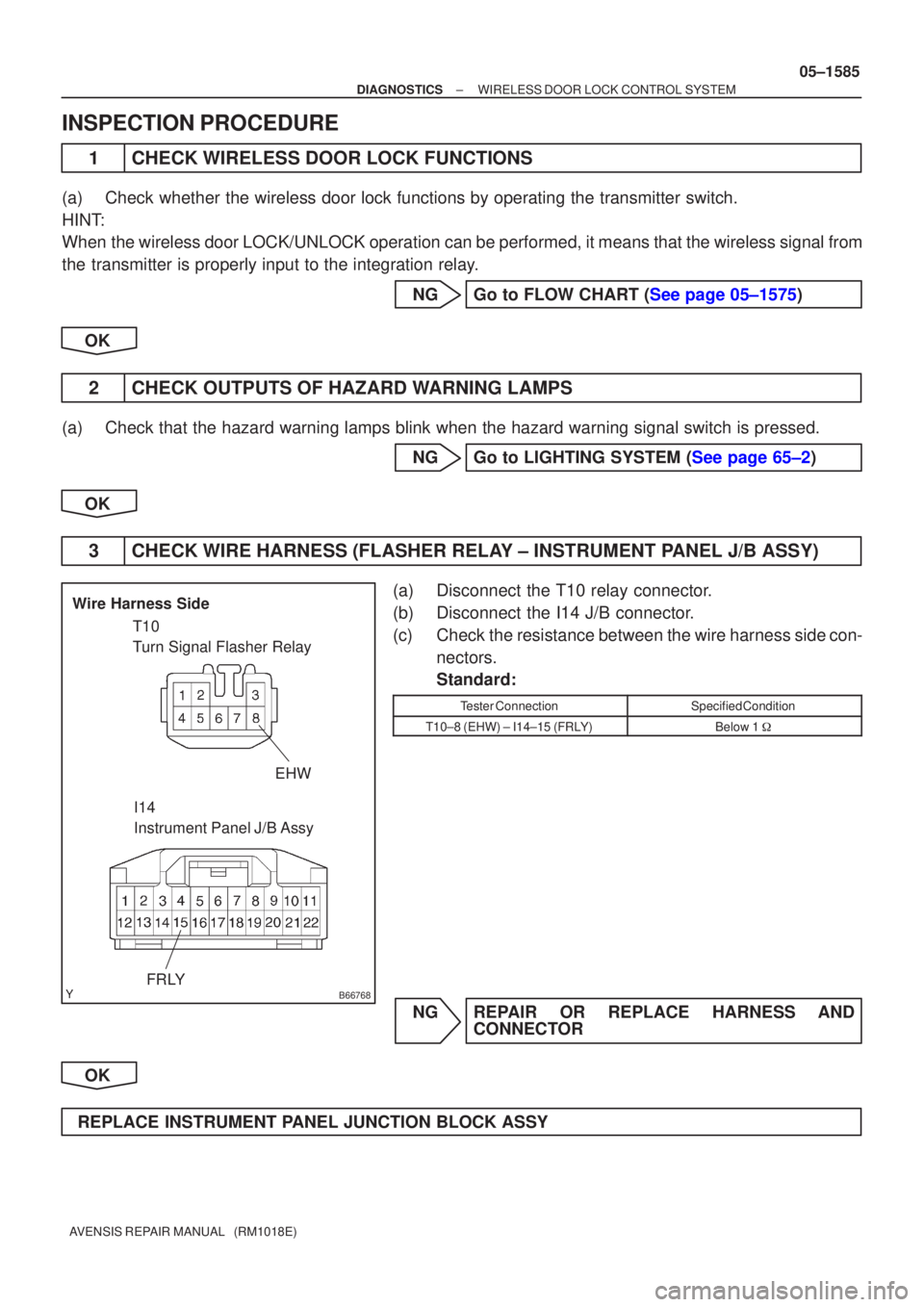
3 CHECK WIRE HARNESS (FLASHER RELAY ± INSTRUMENT PANEL J/B ASSY)
(a) Disconnect the T10 relay connector.
(b) Disconnect the I14 J/B connector.
(c) Check the resistance between the wire harness side con- nectors.
Standard:
Tester ConnectionSpecified Condition
T10±8 (EHW) ± I14±15 (FRLY)Below 1 �
NG REPAIR OR REPLACE HARNESS AND
CONNECTOR
OK
REPLACE INSTRUMENT PANEL JUNCTION BLOCK ASSY
Page 1667 of 5135
05BAA±01
05±1634
±
DIAGNOSTICS THEFT DETERRENT SYSTEM
AVENSIS REPAIR MANUAL (RM1018E)
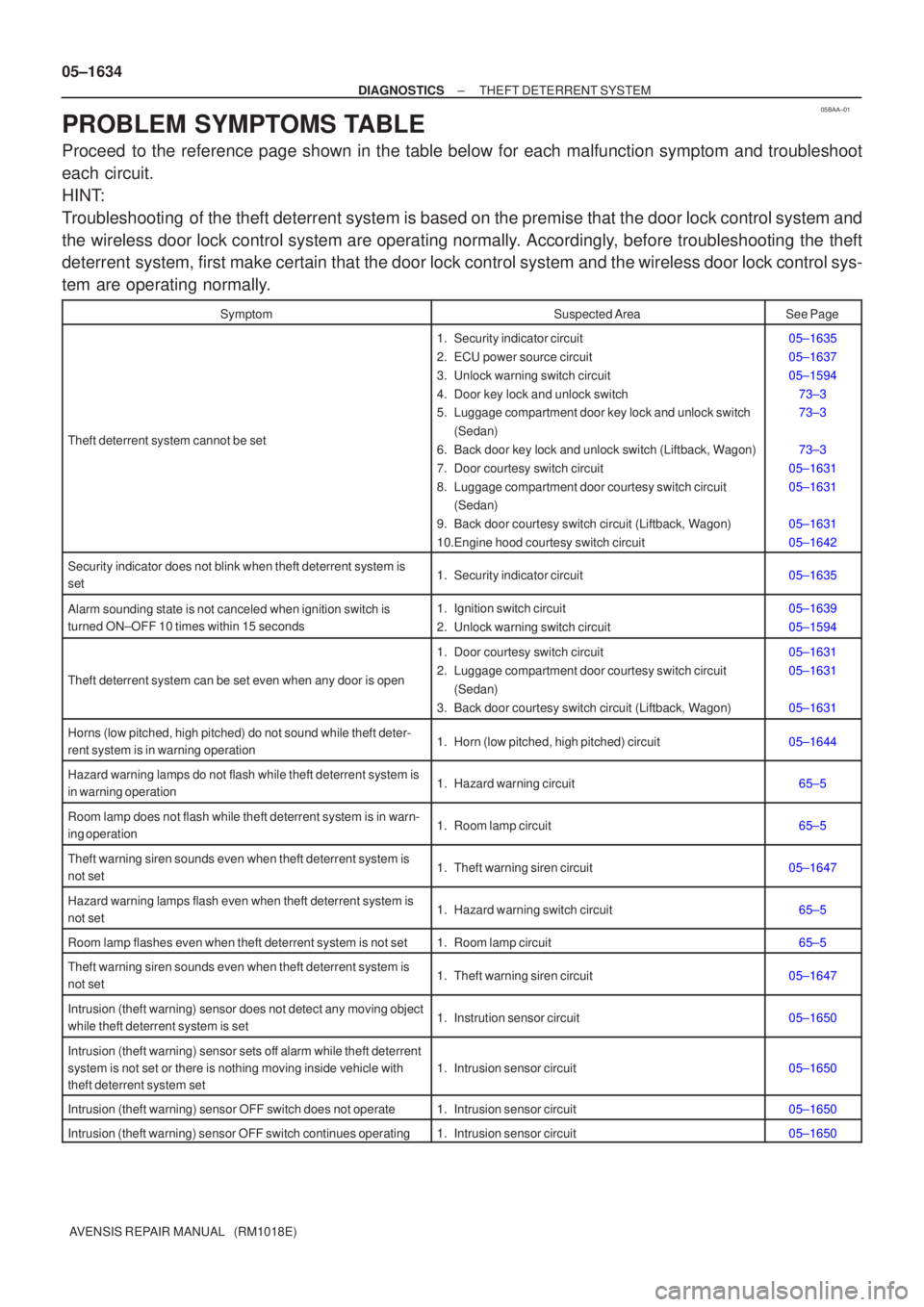
PROBLEM SYMPTOMS TABLE
Proceed to the reference page shown in the table below for each malfunction sym\
ptom and troubleshoot
each circuit.
HINT:
Troubleshooting of the theft deterrent system is based on the premise that the door loc\
k control system and
the wireless door lock control system are operating normally. Accordingly, before troubleshooting the theft
deterrent system, first make certain that the door lock control system and the wireless door lock control sys-
tem are operating normally.
SymptomSuspected AreaSee Page
Theft deterrent system cannot be set
1. Security indicator circuit
2. ECU power source circuit
3. Unlock warning switch circuit
4. Door key lock and unlock switch
5. Luggage compartment door key lock and unlock switch (Sedan)
6. Back door key lock and unlock switch (Liftback, Wagon)
7. Door courtesy switch circuit
8. Luggage compartment door courtesy switch circuit (Sedan)
9. Back door courtesy switch circuit (Liftback, Wagon)
10.Engine hood courtesy switch circuit05±1635
05±1637
05±1594 73±3
73±3
73±3
05±1631
05±1631
05±1631
05±1642
Security indicator does not blink when theft deterrent system is
set1. Security indicator circuit05±1635
Alarm sounding state is not canceled when ignition switch is
turned ON±OFF 10 times within 15 seconds1. Ignition switch circuit
2. Unlock warning switch circuit05±1639
05±1594
Theft deterrent system can be set even when any door is open
1. Door courtesy switch circuit
2. Luggage compartment door courtesy switch circuit (Sedan)
3. Back door courtesy switch circuit (Liftback, Wagon)05±1631
05±1631
05±1631
Horns (low pitched, high pitched) do not sound while theft deter-
rent system is in warning operation1. Horn (low pitched, high pitched) circuit05±1644
Hazard warning lamps do not flash while theft deterrent system is
in warning operation1. Hazard warning circuit65±5
Room lamp does not flash while theft deterrent system is in warn-
ing operation1. Room lamp circuit65±5
Theft warning siren sounds even when theft deterrent system is
not set1. Theft warning siren circuit05±1647
Hazard warning lamps flash even when theft deterrent system is
not set1. Hazard warning switch circuit65±5
Room lamp flashes even when theft deterrent system is not set1. Room lamp circuit65±5
Theft warning siren sounds even when theft deterrent system is
not set1. Theft warning siren circuit05±1647
Intrusion (theft warning) sensor does not detect any moving object
while theft deterrent system is set1. Instrution sensor circuit05±1650
Intrusion (theft warning) sensor sets off alarm while theft deterrent
system is not set or there is nothing moving inside vehicle with
theft deterrent system set
1. Intrusion sensor circuit05±1650
Intrusion (theft warning) sensor OFF switch does not operate1. Intrusion sensor circuit05±1650
Intrusion (theft warning) sensor OFF switch continues operating1. Intrusion sensor circuit05±1650
Page 1672 of 5135
B67698
Front Map Lamp
� Theft Warning Radar Sensor
Hazard Warning LightHazard Warning Light
Hazard Warning Light
Hazard Warning LightHazard Warning Light
Hazard Warning Light
LiftbackSedanFront Courtesy
Lamp Switch Front Door w/ Motor
Lock Assy RH
Front Door w/ Motor
Lock Assy LH
Front Courtesy
Lamp Switch
w/ Motor Back Door Lock Assy
(Back Door Lock Assy)Theft Warning
Siren Assy
w/ Motor Luggage Compartment Door
Lock Assy (Back Door Lock Assy)
Rear Courtesy
Lamp Switch Rear Door w/ Motor
Lock Assy LHRear Theft Warning Radar
Sensor (Wagon only)
Rear Theft Warning Radar
Sensor (Wagon only)
Rear Door w/ Motor
Lock Assy RH
Rear Courtesy
Lamp Switch
w/ Motor Back Door Lock Assy
(Back Door Lock Assy) 05±1630
± DIAGNOSTICSTHEFT DETERRENT SYSTEM
AVENSIS REPAIR MANUAL (RM1018E)
Page 1673 of 5135
05BA7±01
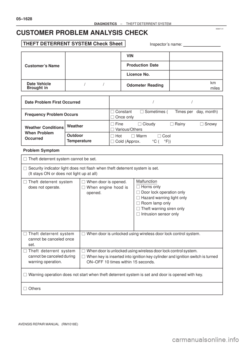
THEFT DETERRENT SYSTEM Check SheetInspector 's name:
Customer 's Name
Date VehicleVIN
Production Date
Licence No.
Odometer Reading / /km
miles
Weather Conditions
When Problem
Occurred Frequency Problem OccursWeather
Outdoor
Temperature
/ /
� Constant � Sometimes ( Times per day, month)
� Once only Brought in
�
Security indicator light does not flash when theft deterrent system is set.
(It stays ON or does not light up at all)
Theft deterrent system
does not operate.When door is opened.
Theft deterrent system
cannot be canceled once
set.�
Theft deterrent system
cannot be canceled during
warning operation.When key is inserted into ignition key cylinder and ignition switch is turned
ON±OFF 10 times within 15 seconds.
Warning operation does not start when theft deterrent system is set and door is opened with key.
�
Date Problem First Occurred
� Fine � Cloudy � Rainy � Snowy
� Various/Others
� Hot � Warm � Cool
� Cold (Approx. �C ( �F))
Problem Symptom
�
�
�
�
� �Malfunction
� Horns only
� Door lock operation only
� Hazard warning light only
� Room lamp only
� Theft warning siren only
� Intrusion sensor only �
�When door is unlocked using wireless door lock control system. When engine hood is
opened.
When door is unlocked using wireless door lock control system.
Others �Theft deterrent system cannot be set. 05±1628
± DIAGNOSTICSTHEFT DETERRENT SYSTEM
AVENSIS REPAIR MANUAL (RM1018E)
CUSTOMER PROBLEM ANALYSIS CHECK
Page 2046 of 5135
A77338
A79320
A79296
A60622
14±30
±
ENGINE MECHANICAL PARTIAL ENGINE ASSY (1ZZ±FE/3ZZ±FE)
AVENSIS REPAIR MANUAL (RM1018E)
32. SEPARATE FLOOR SHIFT CABLE TRANSMISSION CONTROL SELECT (M/T TRANSAXLE) (See page 41±15)
33. SEPARATE FLOOR SHIFT CABLE TRANSMISSION CONTROL SHIFT (M/T TRANSAXLE)
(See page 41±15)
34. SEPARATE FLOOR SHIFT CABLE TRANSMISSION CONTROL SHIFT (A/T TRANSAXLE) (See page 40±11)
35.SEPARATE CLUTCH RELEASE CYLINDER ASSY (M/T TRANSAXLE) (See page 41±15)
36.REMOVE GLOVE COMPARTMENT DOOR ASSY (See page 71±11)
37. REMOVE INSTRUMENT PANEL UNDER COVER SUB±ASSY NO.2
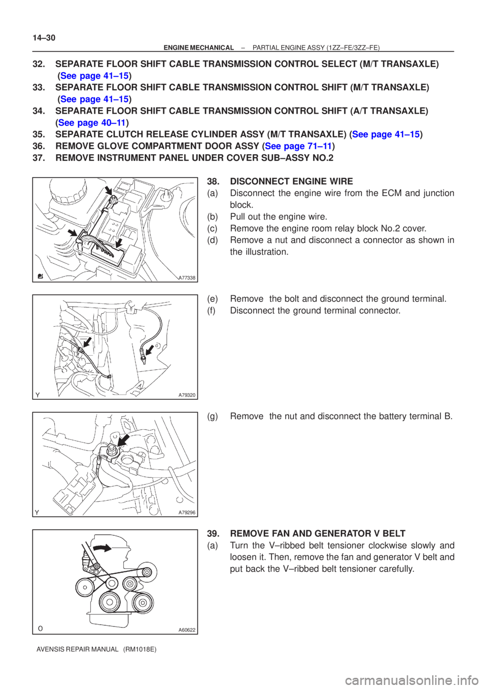
38. DISCONNECT ENGINE WIRE
(a) Disconnect the engine wire from the ECM and junctionblock.
(b) Pull out the engine wire.
(c) Remove the engine room relay block No.2 cover.
(d) Remove a nut and disconnect a connector as shown in the illustration.
(e) Remove the bolt and disconnect the ground terminal.
(f) Disconnect the ground terminal connector.
(g) Remove the nut and disconnect the battery terminal B.
39. REMOVE FAN AND GENERATOR V BELT
(a) Turn the V±ribbed belt tensioner clockwise slowly and loosen it. Then, remove the fan and generator V belt and
put back the V±ribbed belt tensioner carefully.