Page 2073 of 5135
A77338
A77337
A77336
A57550
Engine Hanger No. 1 Engine Hanger No. 2
±
ENGINE MECHANICAL PARTIAL ENGINE ASSY (1AZ±FE)
14±125
AVENSIS REPAIR MANUAL (RM1018E)
55. SEPARATE ENGINE ROOM RELAY BLOCK NO.2
(a) Remove the nut and disconnect the connector as shown
in the illustration.
56. SEPARATE ENGINE WIRE
(a) Remove the bolt and separate the grand terminal.
(b) Separate the grand terminal connector.
(c) Remove the glove compartment door panel.
(d) Separate the engine wire.
57.SEPARATE STEERING INTERMEDIATE SHAFT ASSY NO.2 (See page 50±9) 58. INSTALL ENGINE HANGERS
(a) Install the engine hanger No. 1 (12281±28010, 28020,28030) with the bolt (91512±61020).
Torque: 38 N �m (387 kgf �cm, 28 ft �lbf)
(b) Install the engine hanger No. 2 (12282±28010, 28020, 28030) with the bolt (91512±61020).
Torque: 38 N �m (387 kgf �cm, 28 ft �lbf)
Page 2204 of 5135
A77338
A77337
A77336
A57550
Engine Hanger No. 1Engine Hanger No. 2
14±208
±
ENGINE MECHANICAL PARTIAL ENGINE ASSY(1AZ±FSE)
AVENSIS REPAIR MANUAL (RM1018E)
53.SEPARATE ENGINE ROOM RELAY BLOCK NO.2
(a)Remove the nut and disconnect the connector shown in the illustration.
54.SEPARATE ENGINE WIRE
(a)Remove the bolt and separate the grand terminal.
(b)Separate the grand terminal connector.
(c)Remove the glove compartment door panel.
(d)Separate the engine wire.
55.SEPARATE STEERING INTERMEDIATE SHAFT ASSY NO.2 (See page 50±9) 56. INSTALL ENGINE HANGERS
(a) Install the engine hanger No. 1 (12281±28010, 28020,28030) with the bolt (91512±61020).
Torque: 38 N �m (387 kgf �cm, 28 ft �lbf)
(b) Install the engine hanger No. 2 (12282±28010, 28020, 28030) with the bolt (91512±61020).
Torque: 38 N �m (387 kgf �cm, 28 ft �lbf)
Page 2323 of 5135
A79178
A78277
±
ENGINE MECHANICAL PARTIAL ENGINE ASSY(1CD±FTV)
14±287
AVENSIS REPAIR MANUAL (RM1018E)
24.SEPARATE TRANSMISSION CONTROL CABLE ASSY
(a)Remove the 2 clips and 2 washers, separate the control cable assy.
25.REMOVE INJECTOR DRIVER
(a)Remove the 2 nuts which is used to secure the injector driver.
(b)Disconnect the injector driver connector and the harness clamp.
(c)Remove the injector driver.
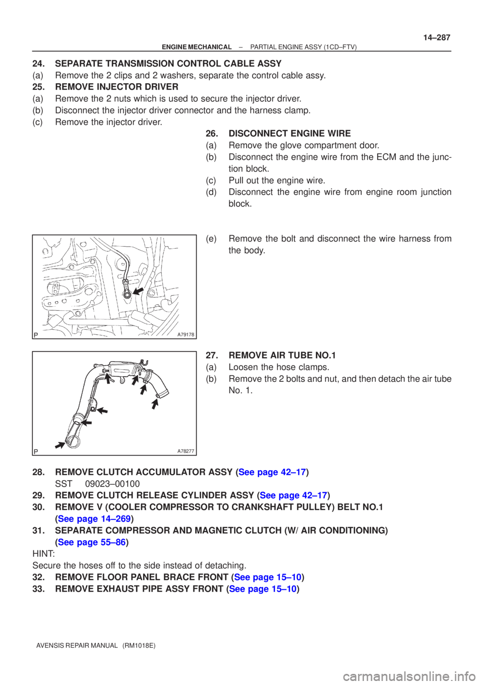
26.DISCONNECT ENGINE WIRE
(a)Remove the glove compartment door.
(b)Disconnect the engine wire from the ECM and the junc-
tion block.
(c)Pull out the engine wire.
(d)Disconnect the engine wire from engine room junction block.
(e)Remove the bolt and disconnect the wire harness from the body.
27.REMOVE AIR TUBE NO.1
(a)Loosen the hose clamps.
(b)Remove the 2 bolts and nut, and then detach the air tube No. 1.
28.REMOVE CLUTCH ACCUMULATOR ASSY (See page 42±17) SST 09023±00100
29.REMOVE CLUTCH RELEASE CYLINDER ASSY (See page 42±17)
30. REMOVE V (COOLER COMPRESSOR TO CRANKSHAFT PULLEY) BELT NO.1
(See page 14±269)
31. SEPARATE COMPRESSOR AND MAGNETIC CLUTCH (W/ AIR CONDITIONING) (See page 55±86)
HINT:
Secure the hoses off to the side instead of detaching.
32.REMOVE FLOOR PANEL BRACE FRONT (See page 15±10)
33.REMOVE EXHAUST PIPE ASSY FRONT (See page 15±10)
Page 3027 of 5135
H42663
H42770
BatterySST(s)
H40007
10 m (33 ft) or more
SST(s)
60±48
±
SUPPLEMENTAL RESTRAINT SYSTEM FRONT SEAT AIRBAG ASSY LH
AVENSIS REPAIR MANUAL (RM1018E)
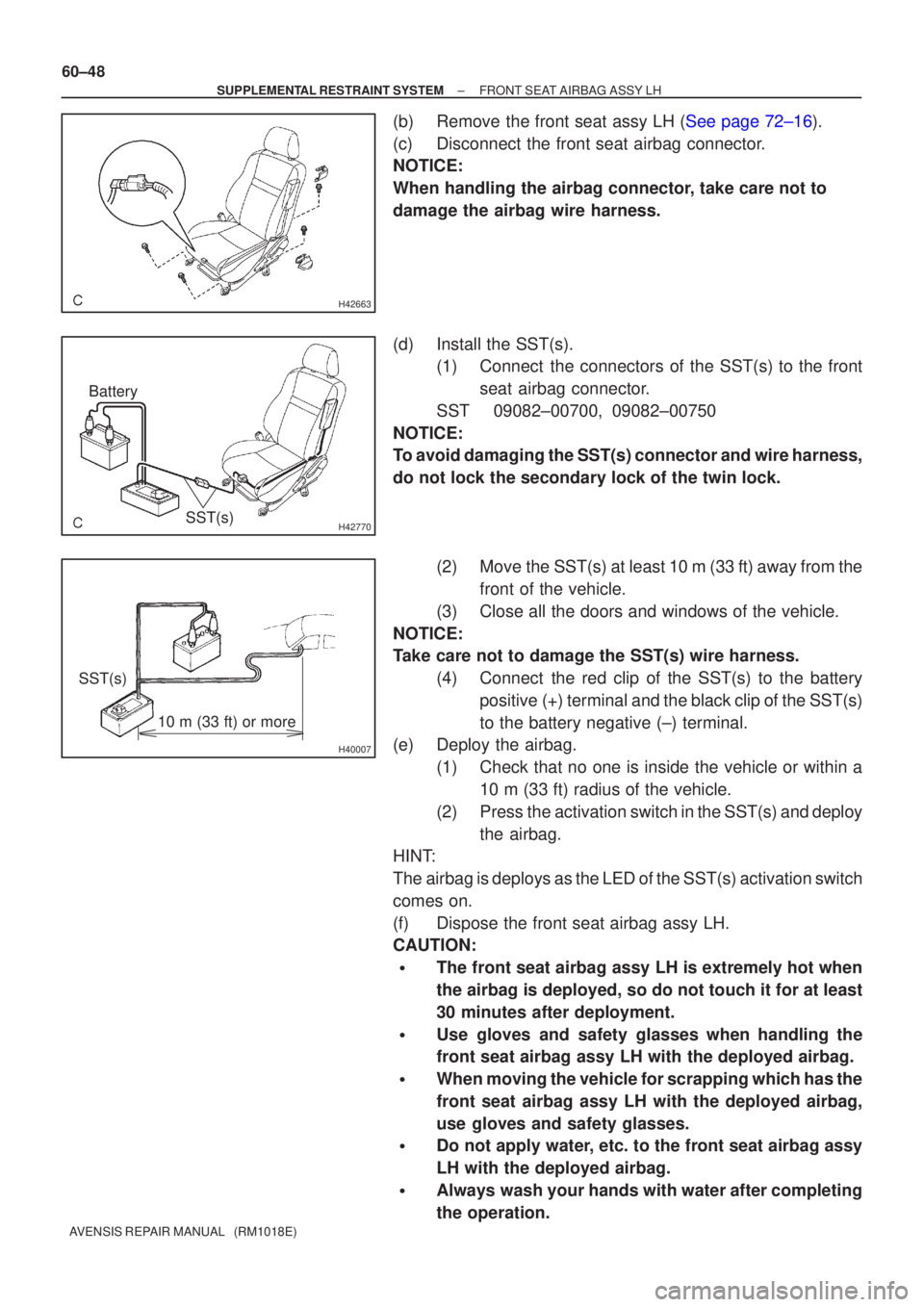
(b)Remove the front seat assy LH (See page 72±16).
(c) Disconnect the front seat airbag connector.
NOTICE:
When handling the airbag connector, take care not to
damage the airbag wire harness.
(d) Install the SST(s). (1) Connect the connectors of the SST(s) to the front
seat airbag connector.
SST 09082±00700, 09082±00750
NOTICE:
To avoid damaging the SST(s) connector and wire harness,
do not lock the secondary lock of the twin lock.
(2) Move the SST(s) at least 10 m (33 ft) away from thefront of the vehicle.
(3) Close all the doors and windows of the vehicle.
NOTICE:
Take care not to damage the SST(s) wire harness. (4) Connect the red clip of the SST(s) to the batterypositive (+) terminal and the black clip of the SST(s)
to the battery negative (±) terminal.
(e) Deploy the airbag.
(1) Check that no one is inside the vehicle or within a10 m (33 ft) radius of the vehicle.
(2) Press the activation switch in the SST(s) and deploy the airbag.
HINT:
The airbag is deploys as the LED of the SST(s) activation switch
comes on.
(f) Dispose the front seat airbag assy LH.
CAUTION:
�The front seat airbag assy LH is extremely hot when
the airbag is deployed, so do not touch it for at least
30 minutes after deployment.
�Use gloves and safety glasses when handling the
front seat airbag assy LH with the deployed airbag.
�When moving the vehicle for scrapping which has the
front seat airbag assy LH with the deployed airbag,
use gloves and safety glasses.
�Do not apply water, etc. to the front seat airbag assy
LH with the deployed airbag.
�Always wash your hands with water after completing
the operation.
Page 3033 of 5135
H42758SST(s)
H41078
10 m (33 ft) or more
SST(s)Battery 60±42
± SUPPLEMENTAL RESTRAINT SYSTEMCURTAIN SHIELD AIR BAG ASSY LH
AVENSIS REPAIR MANUAL (RM1018E)
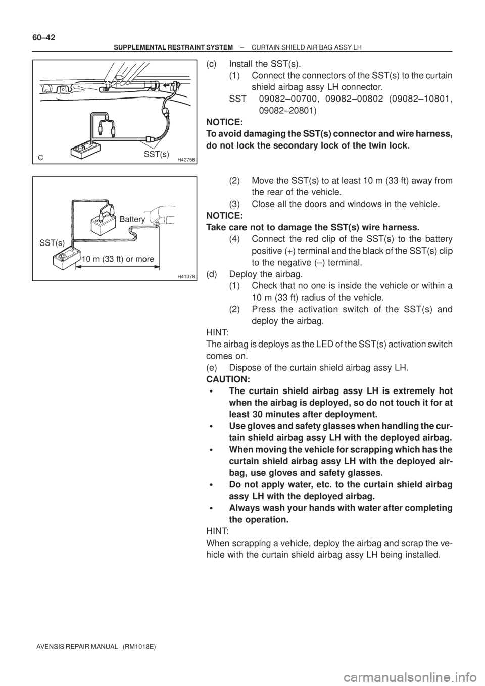
(c) Install the SST(s).
(1) Connect the connectors of the SST(s) to the curtain
shield airbag assy LH connector.
SST 09082±00700, 09082±00802 (09082±10801,
09082±20801)
NOTICE:
To avoid damaging the SST(s) connector and wire harness,
do not lock the secondary lock of the twin lock.
(2) Move the SST(s) to at least 10 m (33 ft) away from
the rear of the vehicle.
(3) Close all the doors and windows in the vehicle.
NOTICE:
Take care not to damage the SST(s) wire harness.
(4) Connect the red clip of the SST(s) to the battery
positive (+) terminal and the black of the SST(s) clip
to the negative (±) terminal.
(d) Deploy the airbag.
(1) Check that no one is inside the vehicle or within a
10 m (33 ft) radius of the vehicle.
(2) Press the activation switch of the SST(s) and
deploy the airbag.
HINT:
The airbag is deploys as the LED of the SST(s) activation switch
comes on.
(e) Dispose of the curtain shield airbag assy LH.
CAUTION:
�The curtain shield airbag assy LH is extremely hot
when the airbag is deployed, so do not touch it for at
least 30 minutes after deployment.
�Use gloves and safety glasses when handling the cur-
tain shield airbag assy LH with the deployed airbag.
�When moving the vehicle for scrapping which has the
curtain shield airbag assy LH with the deployed air-
bag, use gloves and safety glasses.
�Do not apply water, etc. to the curtain shield airbag
assy LH with the deployed airbag.
�Always wash your hands with water after completing
the operation.
HINT:
When scrapping a vehicle, deploy the airbag and scrap the ve-
hicle with the curtain shield airbag assy LH being installed.
Page 3044 of 5135
H42642
H42645
SST(s)
H40007
10 m (33 ft) or more
Battery
SST(s)
±
SUPPLEMENTAL RESTRAINT SYSTEM INSTRUMENT PANEL PASSENGER AIR BAG ASSY
60±31
AVENSIS REPAIR MANUAL (RM1018E)
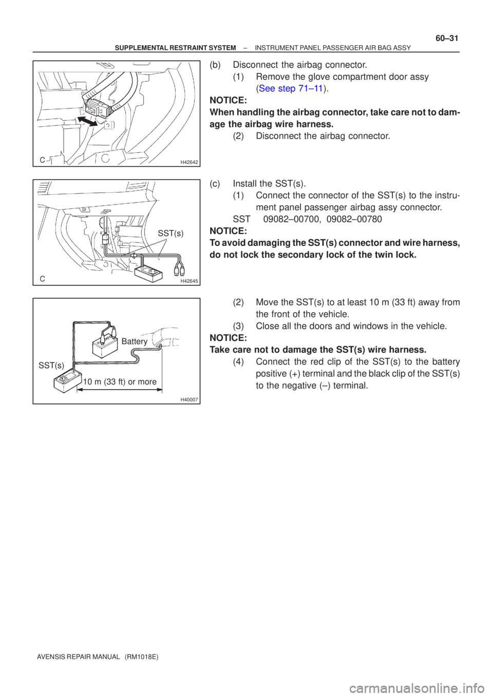
(b) Disconnect the airbag connector.
(1) Remove the glove compartment door assy (See step 71±11).
NOTICE:
When handling the airbag connector, take care not to dam-
age the airbag wire harness. (2) Disconnect the airbag connector.
(c) Install the SST(s). (1) Connect the connector of the SST(s) to the instru-
ment panel passenger airbag assy connector.
SST 09082±00700, 09082±00780
NOTICE:
To avoid damaging the SST(s) connector and wire harness,
do not lock the secondary lock of the twin lock.
(2) Move the SST(s) to at least 10 m (33 ft) away fromthe front of the vehicle.
(3) Close all the doors and windows in the vehicle.
NOTICE:
Take care not to damage the SST(s) wire harness. (4) Connect the red clip of the SST(s) to the batterypositive (+) terminal and the black clip of the SST(s)
to the negative (±) terminal.
Page 3054 of 5135
±
LIGHTING LIGHTING SYSTEM
65±3
AVENSIS REPAIR MANUAL (RM1018E)
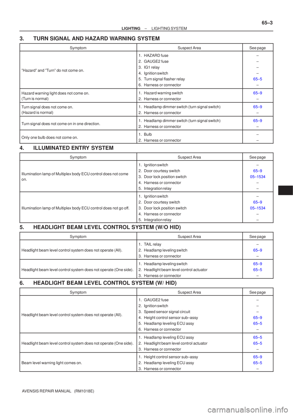
3. TURN SIGNAL AND HAZARD WARNING SYSTEM
SymptomSuspect AreaSee page
ºHazardº and ºTurnº do not come on.
1. HAZARD fuse
2. GAUGE2 fuse
3. IG1 relay
4. Ignition switch
5. Turn signal flasher relay
6. Harness or connector±
±
±
±
65±5
±
Hazard warning light does not come on.
(Turn is normal)1. Hazard warning switch
2. Harness or connector65±9±
Turn signal does not come on.
(Hazard is normal)1. Headlamp dimmer switch (turn signal switch)
2. Harness or connector65±9±
Turn signal does not come on in one direction.1. Headlamp dimmer switch (turn signal switch)
2. Harness or connector65±9±
Only one bulb does not come on.1. Bulb
2. Harness or connector±
±
4. ILLUMINATED ENTRY SYSTEM
SymptomSuspect AreaSee page
Illumination lamp of Multiplex body ECU control does not come
on.
1. Ignition switch
2. Door courtesy switch
3. Door lock position switch
4. Harness or connector
5. Integration relay±
65±9
05±1534 ±
±
Illumination lamp of Multiplex body ECU control does not go off.
1. Ignition switch
2. Door courtesy switch
3. Door lock position switch
4. Harness or connector
5. Integration relay±
65±9
05±1534 ±
±
5. HEADLIGHT BEAM LEVEL CONTROL SYSTEM (W/O HID)
SymptomSuspect AreaSee page
Headlight beam level control system does not operate (All).
1. TAIL relay
2. Headlamp leveling switch
3. Harness or connector±
65±9 ±
Headlight beam level control system does not operate (One side).
1. Headlamp leveling switch
2. Headlight beam level control actuator
3. Harness or connector65±9
65±5±
6. HEADLIGHT BEAM LEVEL CONTROL SYSTEM (W/ HID)
SymptomSuspect AreaSee page
Headlight beam level control system does not operate (All).
1. GAUGE2 fuse
2. Ignition switch
3. Speed sensor signal circuit
4. Height control sensor sub±assy
5. Headlamp leveling ECU assy
6. Harness or connector±
±
±
65±9
65±5 ±
Headlight beam level control system does not operate (One side).
1. Headlamp leveling ECU assy
2. Headlight beam level control actuator
3. Harness or connector65±5
65±5±
Beam level warning light comes on.
1. Height control sensor sub±assy
2. Headlamp leveling ECU assy
3. Harness or connector65±9
65±5±
Page 3072 of 5135
B51763
SST
SST
B50513
10 m or more
±
SEAT BELT FRONT SEAT BELT
61±11
AVENSIS REPAIR MANUAL (RM1018E)
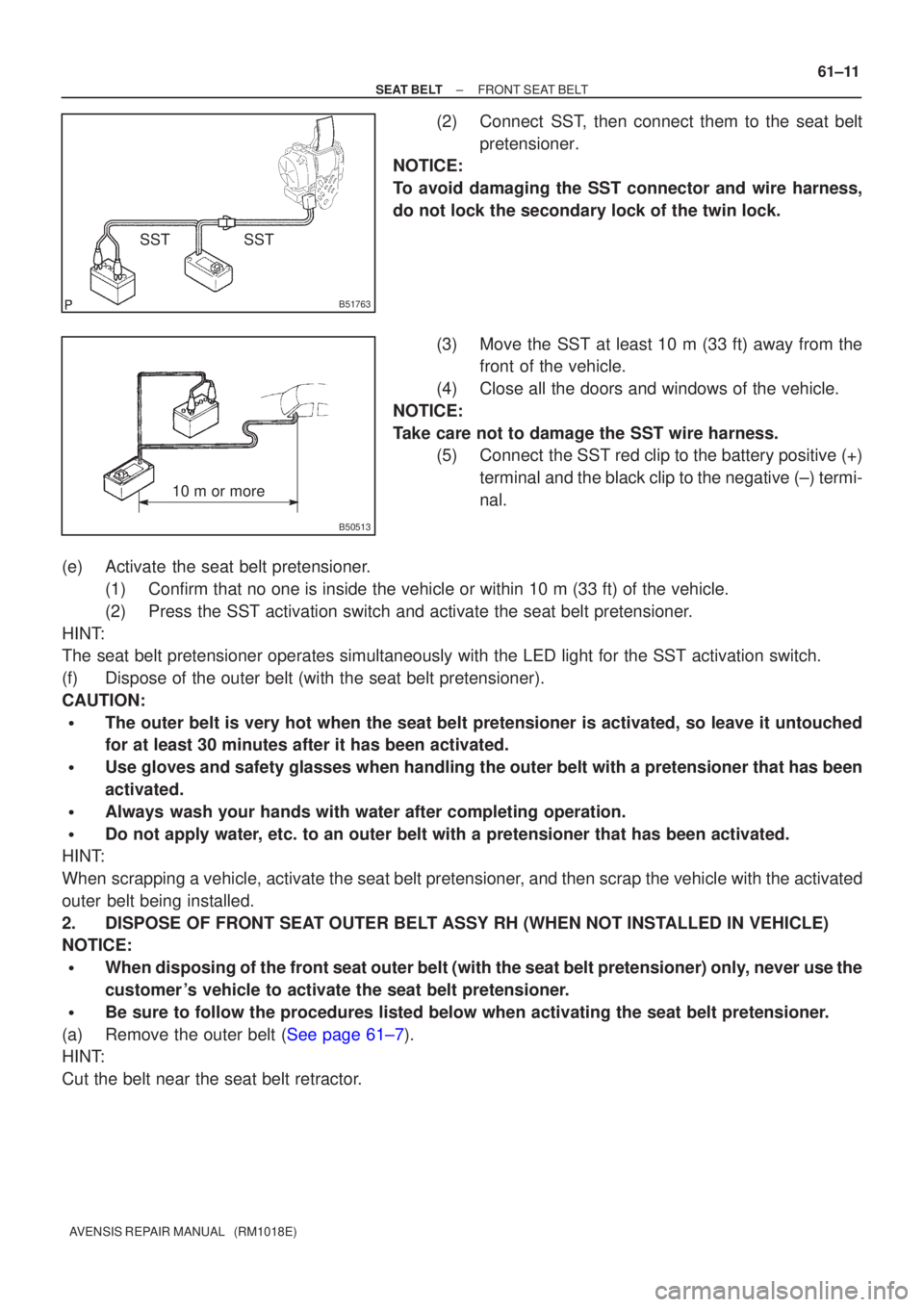
(2) Connect SST, then connect them to the seat belt
pretensioner.
NOTICE:
To avoid damaging the SST connector and wire harness,
do not lock the secondary lock of the twin lock.
(3) Move the SST at least 10 m (33 ft) away from thefront of the vehicle.
(4) Close all the doors and windows of the vehicle.
NOTICE:
Take care not to damage the SST wire harness. (5) Connect the SST red clip to the battery positive (+)
terminal and the black clip to the negative (±) termi-
nal.
(e) Activate the seat belt pretensioner. (1) Confirm that no one is inside the vehicle or within 10 m (33 ft) of th\
e vehicle.
(2) Press the SST activation switch and activate the seat belt pretensioner.
HINT:
The seat belt pretensioner operates simultaneously with the LED light fo\
r the SST activation switch.
(f) Dispose of the outer belt (with the seat belt pretensioner).
CAUTION:
�The outer belt is very hot when the seat belt pretensioner is activated,\
so leave it untouched
for at least 30 minutes after it has been activated.
�Use gloves and safety glasses when handling the outer belt with a pretensio\
ner that has been
activated.
�Always wash your hands with water after completing operation.
�Do not apply water, etc. to an outer belt with a pretensioner that has been activated.
HINT:
When scrapping a vehicle, activate the seat belt pretensioner, and then scrap the vehicle with the activated
outer belt being installed.
2. DISPOSE OF FRONT SEAT OUTER BELT ASSY RH (WHEN NOT INSTALLED IN VEHICLE)
NOTICE:
�When disposing of the front seat outer belt (with the seat belt pretens\
ioner) only, never use the
customer 's vehicle to activate the seat belt pretensioner.
�Be sure to follow the procedures listed below when activating the seat b\
elt pretensioner.
(a)Remove the outer belt (See page 61±7).
HINT:
Cut the belt near the seat belt retractor.