Page 3113 of 5135

I30905
I30905
E64835
65±10
± LIGHTINGLIGHTING SYSTEM
AVENSIS REPAIR MANUAL (RM1018E)
(b) Inspect illumination operation.
(1) Connect the positive (+) lead from the battery to the
terminal 8 and negative (±) lead to the terminal 9,
then check that the illumination comes on.
3. FRONT DOOR COURTESY LAMP SWITCH ASSY
(a) Check that there is continuity between the terminal and the switch body when the switch is operated.
Standard:
ON (When shaft is pressed): No continuity
OFF (When shaft is not pressed): Continuity
4. REAR DOOR COURTESY LAMP SWITCH ASSY
(a) Check that there is continuity between the terminal and the switch body when the switch is operated.
Standard:
ON (When shaft is pressed): No continuity
OFF (When shaft is not pressed): Continuity
5. BACK DOOR LOCK ASSY (WAGON MODELS)
(a) Inspect back door courtesy lamp switch operation.
(1) Check that there is continuity between the terminal
1 and the terminal 2 when the back door is open and
closed.
Standard:
Back door is open: No continuity
Back door is closed: Continuity
6. BACK DOOR LOCK ASSY (LIFTBACK MODELS)
(a) Inspect back door courtesy lamp switch operation.
(1) Check that there is continuity between the terminal
1 and the terminal 2 when the back door is open and
closed.
Standard:
Back door is open: No continuity
Back door is closed: Continuity
7. HEADLAMP RELAY
(a) Inspect relay continuity.
Standard:
ConditionTester connectionSpecified condition
Always1 ± 2Continuity
Always3 ± 5No continuity
Apply B+ between
the terminal 1 and 23 ± 5Continuity
Page 3157 of 5135
I35750
RELAY
A. ±
B. HTR
C. SEAT HTR
D. IG1
E. TAILFUSE
1. IGN 10A
2. S/ROOF 20A
3. RR FOG 7.5A
4. FR FOG 7.5A
5. AM1 25A
6. PANEL 7.5A
7. RR WIP 20A
8. GAUGE2 7.5A
9. CIG 15A
10.HTR 10A
11. ±
12. RAD No.1 7.5A
A. HORN
B. F±HTR
C. H±LP
D. DIM
E. FAN No.2RELAY
1. H±LP HI LH 10A
2. H±LP HI RH 10A
3. H±LP LH 15A
4. H±LP RH 15AFUSE A
B
13
14
15
9
103
4
5
6
7
8
1
3
4 2CD
E
16
17
18
19
20
21
22 12 111
2
A
BCDE13. PWR SEAT 30A
14. TAIL 10A
15. OBD2 7.5A
16. P/POINT 15A
17. DOOR 25A
18. WIP 25A
19. EGU±IG 7.5A
20. S±HTR 20A
21. GAUGE1 10A
22. STOP 15A Instrument Panel Junction Block Assy
Engine Room Relay No.3 Block
± WIRINGPOWER SOURCE
68±5
AVENSIS REPAIR MANUAL (RM1018E)
Page 3174 of 5135
700TA±01
B68025
Clip
Piano Wire
B69236
Protective Tape
BO4421
±
WINDSHIELD/WINDOWGLASS/MIRROR BACK DOOR GLASS (WAGON MODELS)
70±41
AVENSIS REPAIR MANUAL (RM1018E)
REPLACEMENT
HINT:
The installation is in the reverse order of the removal. However, when there is a special point concerning
the installation, it is indicated.
1.REMOVE BACK DOOR TRIM BOARD ASSY (See page 75±45)
(a) Remove the back door trim panel upper.
(b) Remove the back door side garnish LH.
(c) Remove the back door side garnish RH.
(d) Remove the back door trim board.
2.REMOVE REAR SPOILER (See page 76±30)
3.REMOVE REAR WIPER MOTOR ASSY (See page 66±17)
(a) Remove the wiper arm head cap.
(b) Remove the rear wiper arm.
(c) Remove the wiper motor.
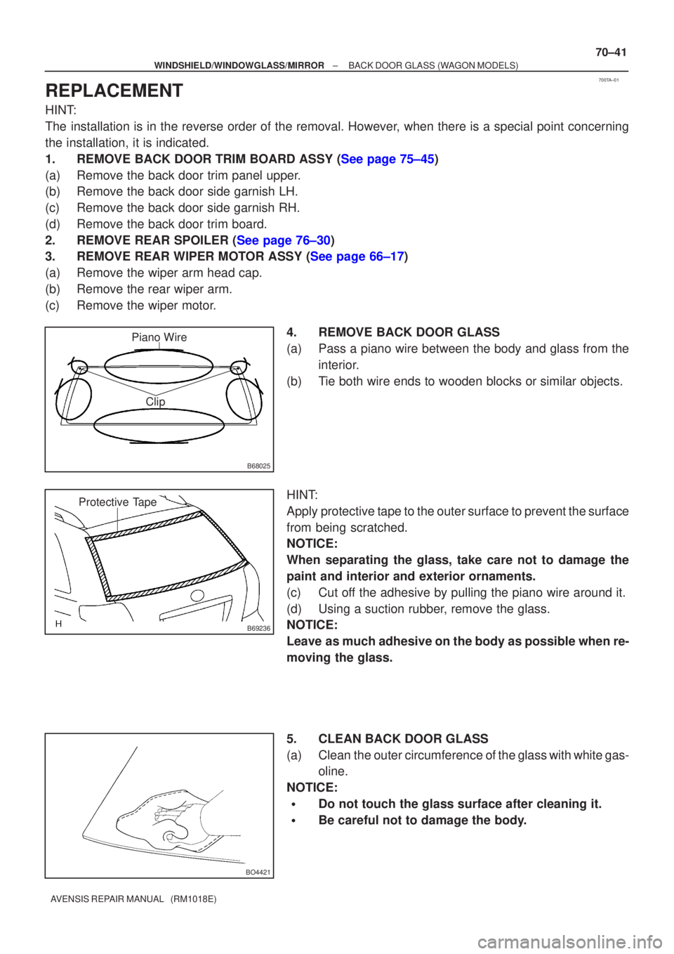
4. REMOVE BACK DOOR GLASS
(a) Pass a piano wire between the body and glass from theinterior.
(b) Tie both wire ends to wooden blocks or similar objects.
HINT:
Apply protective tape to the outer surface to prevent the surface
from being scratched.
NOTICE:
When separating the glass, take care not to damage the
paint and interior and exterior ornaments.
(c) Cut off the adhesive by pulling the piano wire around it.
(d) Using a suction rubber, remove the glass.
NOTICE:
Leave as much adhesive on the body as possible when re-
moving the glass.
5. CLEAN BACK DOOR GLASS
(a) Clean the outer circumference of the glass with white gas- oline.
NOTICE:
�Do not touch the glass surface after cleaning it.
�Be careful not to damage the body.
Page 3180 of 5135
700T8±01
B68025
Piano Wire
Clip
B69235
Protective Tape
±
WINDSHIELD/WINDOWGLASS/MIRROR BACK DOOR GLASS (LIFTBACK MODELS)
70±35
AVENSIS REPAIR MANUAL (RM1018E)
REPLACEMENT
HINT:
The installation is in the reverse order of the removal. However, when there is a special point concerning
the installation, it is indicated.
1.REMOVE BACK DOOR TRIM BOARD ASSY (See page 75±40)
(a) Remove the back door trim panel assy upper.
(b) Remove the back door side garnish LH.
(c) Remove the back door side garnish RH.
(d) Remove the back door trim board.
2.REMOVE CENTER STOP LAMP ASSY (See page 65±26)
3.REMOVE REAR WIPER MOTOR ASSY (
See page 66±17)
(a) Remove the wiper arm head cap.
(b) Remove the rear wiper arm.
(c) Remove the wiper motor.
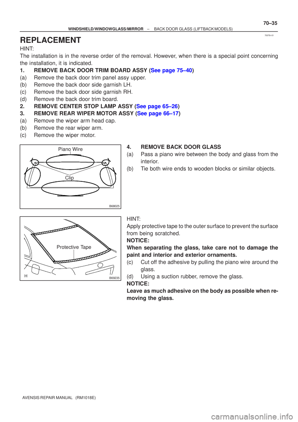
4. REMOVE BACK DOOR GLASS
(a) Pass a piano wire between the body and glass from theinterior.
(b) Tie both wire ends to wooden blocks or similar objects.
HINT:
Apply protective tape to the outer surface to prevent the surface
from being scratched.
NOTICE:
When separating the glass, take care not to damage the
paint and interior and exterior ornaments.
(c) Cut off the adhesive by pulling the piano wire around the glass.
(d) Using a suction rubber, remove the glass.
NOTICE:
Leave as much adhesive on the body as possible when re-
moving the glass.
Page 3186 of 5135
700T6±01
B50453
CutCut
B62805
Stopper
Piano Wire
70±28
±
WINDSHIELD/WINDOWGLASS/MIRROR BACK WINDOW GLASS (SEDAN MODELS)
AVENSIS REPAIR MANUAL (RM1018E)
REPLACEMENT
HINT:
The installation is in the reverse order of the removal. However, when there is a special point concerning
the installation, it is indicated.
1 . REMOVE REAR SE AT CUSHION ASSY ( See page 72±27 or 72±32 )
2 . REMOVE REAR SE ATBACK ASSY ( See page 72±27 or 72±32 )
3 . REMOVE ROOF HEADLINING ASSY ( See page 76±36)
(a) Remove the rear door weatherstrip LH.
(b) Remove the rear door weatherstrip RH.
(c) Remove the roof side garnish inner LH.
(d) Remove the roof side garnish inner RH.
(e) Remove the 2 assist grips.
(f) Remove the rear map lamp.
(g) Remove the roof headlining assy.
4 . REMOVE CENTER S TOP LAMP ASSY ( See page 65±26)
5 . REMOVE P ACKAGE TR AY TRIM P ANEL ASSY ( See page 61±15 )
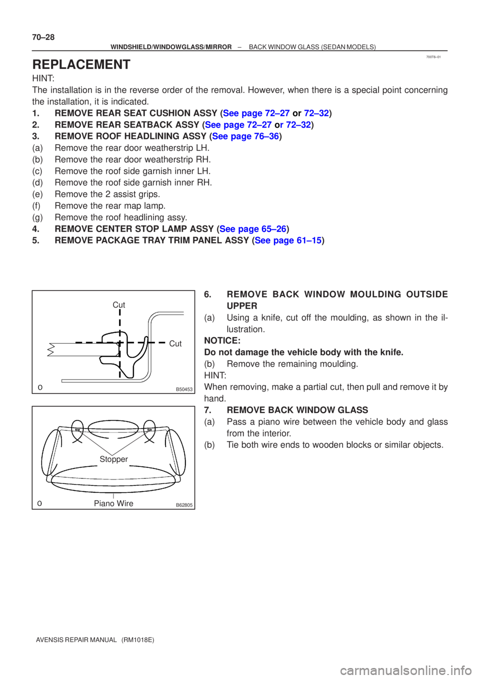
6. REMOVE BACK WINDOW MOULDING OUTSIDE UPPER
(a) Using a knife, cut off the moulding, as shown in the il- lustration.
NOTICE:
Do not damage the vehicle body with the knife.
(b) Remove the remaining moulding.
HINT:
When removing, make a partial cut, then pull and remove it by
hand.
7. REMOVE BACK WINDOW GLASS
(a) Pass a piano wire between the vehicle body and glass
from the interior.
(b) Tie both wire ends to wooden blocks or similar objects.
Page 3193 of 5135
700T4±01
B68022
Piano Wire
Clip
Clip
B68023
Protective Tape
±
WINDSHIELD/WINDOWGLASS/MIRROR QUARTER WINDOW ASSY LH (WAGON MODELS)
70±23
AVENSIS REPAIR MANUAL (RM1018E)
REPLACEMENT
HINT:
�The installation is in the reverse order of the removal. However, when there is a special point concern-
ing the installation, it is indicated.
�Use the same procedures on the RH side as on the LH side.
1.REMOVE REAR WINDOW SIDE GARNISH LH (See page 76±54)
(a) Remove the rear door opening trim weatherstrip LH
(b) Remove the rear door scuff plate.
(c) Remove the tonneau cover.
(d) Remove the deck board.
(e) Remove the deck floor box rear.
(f) Remove the deck floor box.
(g) Remove the deck floor box front.
(h) Remove the rear floor finish plate.
(i) Remove the roof headlining retainer front.
(j) Remove the luggage compartment trim hook No. 2.
(k) Remove the deck trim side board.
(l) Remove the roof side garnish inner.
(m) Remove the rear window side garnish.
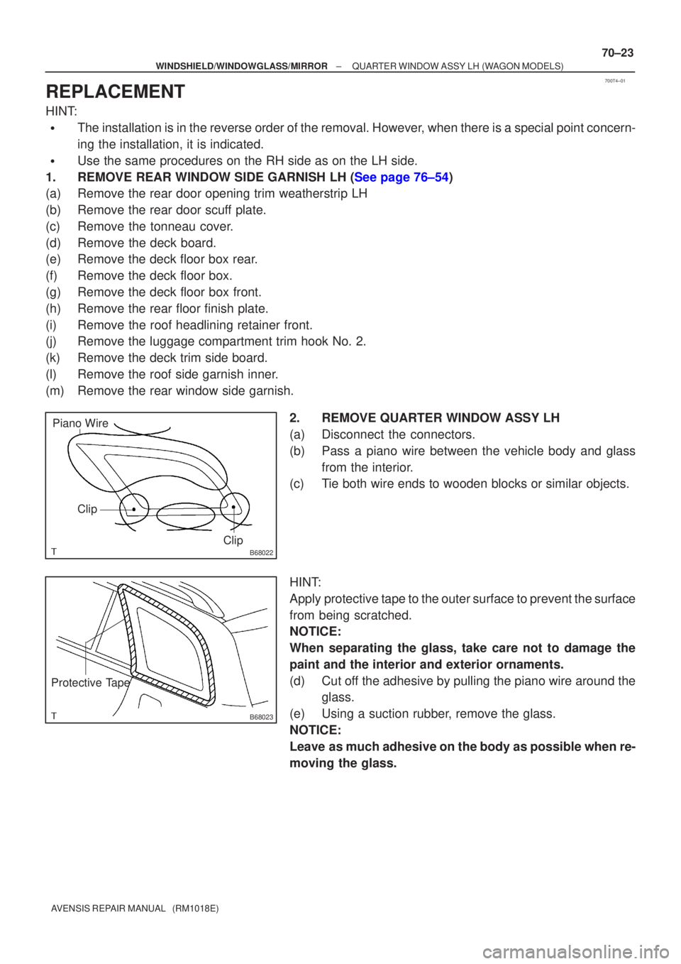
2. REMOVE QUARTER WINDOW ASSY LH
(a) Disconnect the connectors.
(b) Pass a piano wire between the vehicle body and glassfrom the interior.
(c) Tie both wire ends to wooden blocks or similar objects.
HINT:
Apply protective tape to the outer surface to prevent the surface
from being scratched.
NOTICE:
When separating the glass, take care not to damage the
paint and the interior and exterior ornaments.
(d) Cut off the adhesive by pulling the piano wire around the glass.
(e) Using a suction rubber, remove the glass.
NOTICE:
Leave as much adhesive on the body as possible when re-
moving the glass.
Page 3214 of 5135

700S9±01
±
WINDSHIELD/WINDOWGLASS/MIRROR POWER WINDOW CONTROL SYSTEM
70±5
AVENSIS REPAIR MANUAL (RM1018E)
PROBLEM SYMPTOMS TABLE
SymptomSuspected AreaSee Page
All power windows do not operate
1. Ignition switch assy
2. IG1 relay
3. Power window regulator master switch assy
4. Instrument panel J/B assy (Integration relay)
5. Wire harness80±2
70±6
70±6
70±6
±
Only one power window does not operate
1. D±FR P/W fuse
2. P±FR P/W fuse
3. D±RR P/W fuse
4. P±RR P/W fuse
5. Power window regulator master switch assy
6. Power window regulator switch assy
7. Door window regulator sub±assy (Power window
motor)
8. Wire harness±
±
±
±
70±6
70±6
70±6
±
AUTO UP/DOWN function does not operate
1. Power window regulator master switch assy
2. Power window regulator switch assy
3. Door window regulator sub±assy (Power window motor)70±6
70±6
70±6
Window lock system does not operate1. Power window master switch assy70±6
Window cannot be operated after ignition switch is turned OFF1. Front door courtesy lamp switch assy
2. Instrument panel J/B assy (Integration relay)70±6
70±6
Page 3218 of 5135
B51853
Hammer 70±2
± WINDSHIELD/WINDOWGLASS/MIRRORPOWER WINDOW CONTROL SYSTEM
AVENSIS REPAIR MANUAL (RM1018E)
4. CHECK REMOTE UP/DOWN FUNCTION
(a) Check that each switch of the power window master switch can operate each power window as follows:
Standard:
ConditionMaster SwitchSwitch OperationPower Window
Passenger sideHalfway pulled UPUP (Closed)Passenger sideHalfway pushed DOWNDOWN (Open)
�Ignition switch ONRear LHHalfway pulled UPUP (Closed)Ignition switch ON
�Window lock switch OFFRear LHHalfway pushed DOWNDOWN (Open)
Rear RHHalfway pulled UPUP (Closed)Rear RHHalfway pushed DOWNDOWN (Open)
5. CHECK REMOTE AUTO UP/DOWN FUNCTION
(a) Check that each switch of the power window master switch can operate each power window as follows:
Standard:
ConditionMaster SwitchSwitch OperationPower Window
Passenger sideFully pulled UPAUTO UP (Fully closed)Passenger sideFully pushed DOWNAUTO DOWN (Fully open)
�Ignition switch ONRear LHFully pulled UPAUTO UP (Fully closed)Ignition switch ON
�Window lock switch OFFRear LHFully pushed DOWNAUTO DOWN (Fully open)
Rear RHFully pulled UPAUTO UP (Fully closed)Rear RHFully pushed DOWNAUTO DOWN (Fully open)
6. CHECK POWER WINDOW OPERATION FUNCTION AFTER IGNITION SWITCH IS TURNED OFF
(a) When both of the following conditions are fulfilled, check that the power windows can be operated even
after the ignition switch is turned OFF.
�Within 45 seconds after the ignition switch is turned OFF
�The front doors are closed
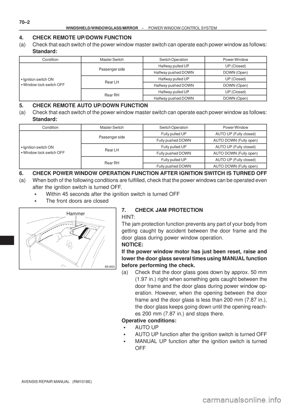
7. CHECK JAM PROTECTION
HINT:
The jam protection function prevents any part of your body from
getting caught by accident between the door frame and the
door glass during power window operation.
NOTICE:
If the power window motor has just been reset, raise and
lower the door glass several times using MANUAL function
before performing the check.
(a) Check that the door glass goes down by approx. 50 mm
(1.97 in.) right when something gets caught between the
door frame and the door glass during power window op-
eration. However, when the opening between the door
frame and the door glass is less than 200 mm (7.87 in.),
the door glass keeps going down until the opening reach-
es 200 mm (7.87 in.) and stops there.
Operative conditions:
�AUTO UP
�AUTO UP function after the ignition switch is turned OFF
�MANUAL UP function after the ignition switch is turned
OFF