Page 3403 of 5135
750N7±01
B66987
Back Door Trim Panel Assy Upper
Back Door Side Garnish LH Wiper Motor AssyRear Spoiler
Back Door Garnish Sub±assy Outside RH
Back Door Trim Board Assy
Door Pull Handle
Back Door Lock Striker Back Door Side Garnish RH
Door Pull Handle
: Specified torque
N´m (kgf´cm, ft´lbf)
Floor Finish Plate Rear Wiper Arm and Blade Assy
Wiper Arm Head Cap
5.5 (56, 49 in.´lbf)
Rear Wiper w/ Packing
Washer
Back Door
Stay Assy LH
7.0 (71, 62 in.´lbf)
22 (264, 19)
11.5 (120, 8)
Back Door Stay Assy RH
7.0 (71, 62 in.´lbf)
8.0 (82, 71 in.´lbf)
19.5 (200, 14)
Back Door Service Hole Cover
Back Door Lock Assy
4.9 (49, 43 in.´lbf)4.9 (49, 43 in.´lbf)
75±42
± ENGINE HOOD/DOORBACK DOOR (WAGON MODELS)
AVENSIS REPAIR MANUAL (RM1018E)
BACK DOOR (WAGON MODELS)
COMPONENTS
Page 3405 of 5135
B66996
B66996
B66991
±
ENGINE HOOD/DOOR BACK DOOR (LIFTBACK MODELS)
75±41
AVENSIS REPAIR MANUAL (RM1018E)
9. REMOVE BACK DOOR LOCK ASSY
(a) Disconnect the connector.
(b) Remove the 3 bolts and door lock.
10.REMOVE BACK DOOR STAY ASSY LH (See page 75±47)
11.REMOVE BACK DOOR STAY ASSY RH (See page 75±47) 12. INSTALL BACK DOOR LOCK ASSY
(a) Install the door lock with the 3 bolts.Torque: 8.0 N �m (82 kgf �cm, 71 in. �lbf)
(b) Connect the door lock connector
13. INSTALL BACK DOOR DAMPER ASSY
(a) Install the damper with the 4 bolts. Torque: 5.5 N �m (56 kgf �cm, 49 in. �lbf)
Page 3408 of 5135
750N4±01
B66986
Back Door Trim
Panel Assy Upper
Back Door Trim Board Assy Back Door Side
Garnish LHBack Door Garnish Sub±assy
Outside RH
Floor Finish Plate Center Stop Lamp Assy
Back Door Lock Striker Hook
Back Door Side
Garnish RHBack Door Stay Assy RH
Back Door Lock Assy Rear Wiper Motor Assy
Back Door
Stay Assy LH
Back Door Service
Hole Cover
: Specified torqueN´m (kgf´cm, ft´lbf)
19.5 (200, 14)
5.5 (56, 49 in.´lbf)
Hook Rear Wiper Arm and Blade Assy
Rear Wiper
w/ Packing Washer
Wiper Arm Head Cap
Nut5.5 (56, 49 in.´lbf)
5.5 (56, 49 in.´lbf)
Cushion Rubber
Cushion Rubber
Rope Hook Assy
11.5 (120, 8)
22 (264, 19)
7.0 (71, 62 in.´lbf)
5.5 (56, 49 in.´lbf)
8.0 (82, 71 in.´lbf)
7.0 (71, 62 in.´lbf)22 (264, 19)
Female
Stopper RH
Female
Stopper LH
4.9 (49, 43 in.´lbf)Back Door Damper Assy
5.5 (56, 49 in.´lbf)
± ENGINE HOOD/DOORBACK DOOR (LIFTBACK MODELS)
75±37
AVENSIS REPAIR MANUAL (RM1018E)
BACK DOOR (LIFTBACK MODELS)
COMPONENTS
Page 3433 of 5135

760WD±01
B67161
Clip
B67162
Clip
B67163
Double±sided Tape
76±30
± EXTERIOR/INTERIOR TRIMREAR SPOILER (WAGON MODELS)
AVENSIS REPAIR MANUAL (RM1018E)
REAR SPOILER (WAGON MODELS)
REPLACEMENT
HINT:
The installation is in the reverse order of the removal.
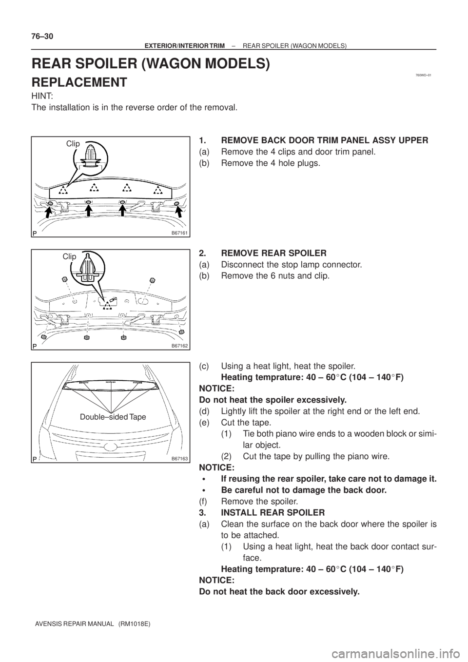
1. REMOVE BACK DOOR TRIM PANEL ASSY UPPER
(a) Remove the 4 clips and door trim panel.
(b) Remove the 4 hole plugs.
2. REMOVE REAR SPOILER
(a) Disconnect the stop lamp connector.
(b) Remove the 6 nuts and clip.
(c) Using a heat light, heat the spoiler.
Heating temprature: 40 ± 60�C (104 ± 140�F)
NOTICE:
Do not heat the spoiler excessively.
(d) Lightly lift the spoiler at the right end or the left end.
(e) Cut the tape.
(1) Tie both piano wire ends to a wooden block or simi-
lar object.
(2) Cut the tape by pulling the piano wire.
NOTICE:
�If reusing the rear spoiler, take care not to damage it.
�Be careful not to damage the back door.
(f) Remove the spoiler.
3. INSTALL REAR SPOILER
(a) Clean the surface on the back door where the spoiler is
to be attached.
(1) Using a heat light, heat the back door contact sur-
face.
Heating temprature: 40 ± 60�C (104 ± 140�F)
NOTICE:
Do not heat the back door excessively.
Page 4650 of 5135

A84285
A87968
Air Hose No. 3
(a)(b)
(a)
(b)
A79178
− ENGINE MECHANICALPARTIAL ENGINE ASSY (1CD−FTV)(From September,
2003)14−109
AVENSIS Supplement (RM1045E)
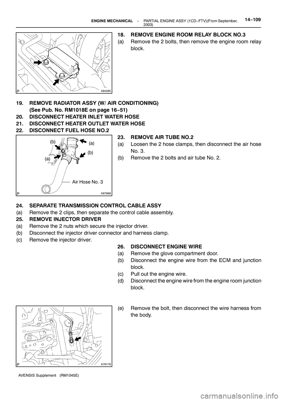
18. REMOVE ENGINE ROOM RELAY BLOCK NO.3
(a) Remove the 2 bolts, then remove the engine room relay
block.
19. REMOVE RADIATOR ASSY (W/ AIR CONDITIONING)
(See Pub. No. RM1018E on page 16−51)
20. DISCONNECT HEATER INLET WATER HOSE
21. DISCONNECT HEATER OUTLET WATER HOSE
22. DISCONNECT FUEL HOSE NO.2
23. REMOVE AIR TUBE NO.2
(a) Loosen the 2 hose clamps, then disconnect the air hose
No. 3.
(b) Remove the 2 bolts and air tube No. 2.
24. SEPARATE TRANSMISSION CONTROL CABLE ASSY
(a) Remove the 2 clips, then separate the control cable assembly.
25. REMOVE INJECTOR DRIVER
(a) Remove the 2 nuts which secure the injector driver.
(b) Disconnect the injector driver connector and harness clamp.
(c) Remove the injector driver.
26. DISCONNECT ENGINE WIRE
(a) Remove the glove compartment door.
(b) Disconnect the engine wire from the ECM and junction
block.
(c) Pull out the engine wire.
(d) Disconnect the engine wire from the engine room junction
block.
(e) Remove the bolt, then disconnect the wire harness from
the body.
Page 5068 of 5135

A76724
A76714
A77338
– ENGINE MECHANICALPARTIAL ENGINE ASSY (1ZZ–FE/3ZZ–FE)(From
February, 2004)14–11
AVENSIS REPAIR MANUAL SUPPLEMENT
(RM1098E)
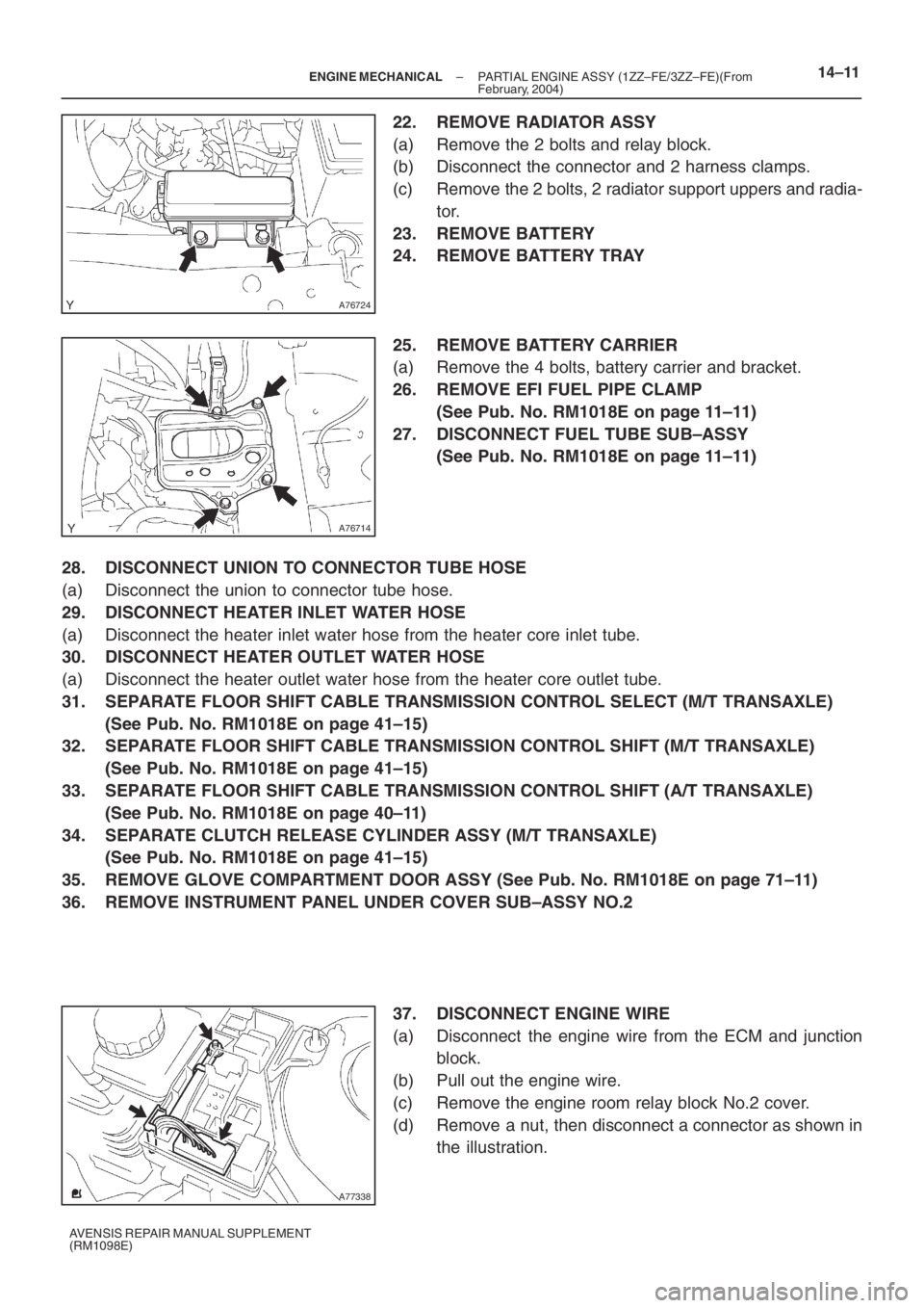
22. REMOVE RADIATOR ASSY
(a) Remove the 2 bolts and relay block.
(b) Disconnect the connector and 2 harness clamps.
(c) Remove the 2 bolts, 2 radiator support uppers and radia-
tor.
23. REMOVE BATTERY
24. REMOVE BATTERY TRAY
25. REMOVE BATTERY CARRIER
(a) Remove the 4 bolts, battery carrier and bracket.
26. REMOVE EFI FUEL PIPE CLAMP
(See Pub. No. RM1018E on page 11–11)
27. DISCONNECT FUEL TUBE SUB–ASSY
(See Pub. No. RM1018E on page 11–11)
28. DISCONNECT UNION TO CONNECTOR TUBE HOSE
(a) Disconnect the union to connector tube hose.
29. DISCONNECT HEATER INLET WATER HOSE
(a) Disconnect the heater inlet water hose from the heater core inlet tube.
30. DISCONNECT HEATER OUTLET WATER HOSE
(a) Disconnect the heater outlet water hose from the heater core outlet tube.
31. SEPARATE FLOOR SHIFT CABLE TRANSMISSION CONTROL SELECT (M/T TRANSAXLE)
(See Pub. No. RM1018E on page 41–15)
32. SEPARATE FLOOR SHIFT CABLE TRANSMISSION CONTROL SHIFT (M/T TRANSAXLE)
(See Pub. No. RM1018E on page 41–15)
33. SEPARATE FLOOR SHIFT CABLE TRANSMISSION CONTROL SHIFT (A/T TRANSAXLE)
(See Pub. No. RM1018E on page 40–11)
34. SEPARATE CLUTCH RELEASE CYLINDER ASSY (M/T TRANSAXLE)
(See Pub. No. RM1018E on page 41–15)
35. REMOVE GLOVE COMPARTMENT DOOR ASSY (See Pub. No. RM1018E on page 71–11)
36. REMOVE INSTRUMENT PANEL UNDER COVER SUB–ASSY NO.2
37. DISCONNECT ENGINE WIRE
(a) Disconnect the engine wire from the ECM and junction
block.
(b) Pull out the engine wire.
(c) Remove the engine room relay block No.2 cover.
(d) Remove a nut, then disconnect a connector as shown in
the illustration.
Page 5069 of 5135

A79320
(f)
(e)
A79296
A60622
14–12– ENGINE MECHANICALPARTIAL ENGINE ASSY (1ZZ–FE/3ZZ–FE)(From
February, 2004)
AVENSIS REPAIR MANUAL SUPPLEMENT
(RM1098E)
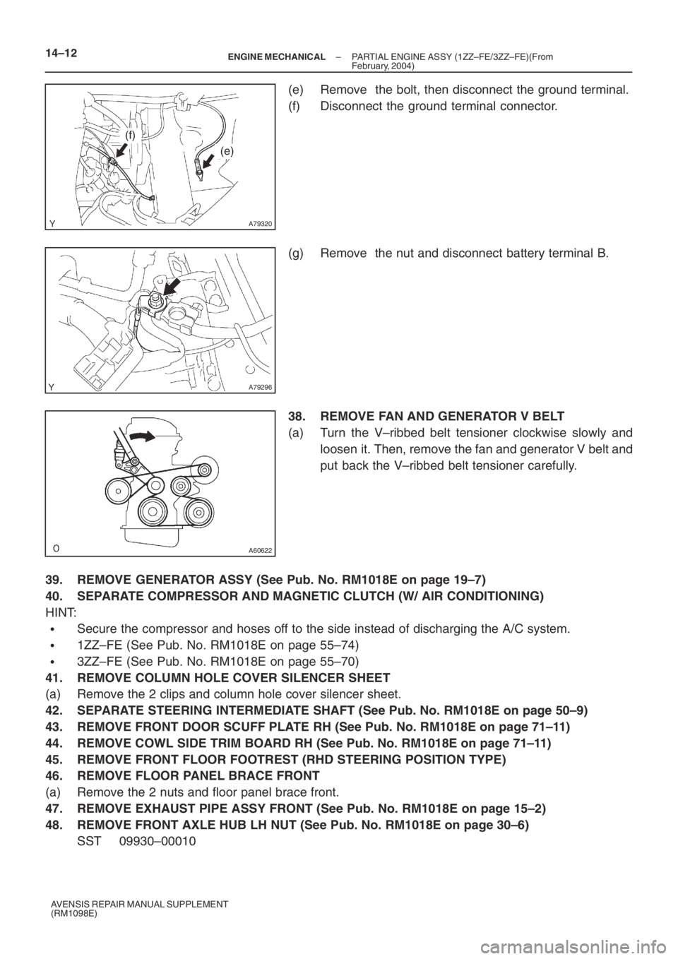
(e) Remove the bolt, then disconnect the ground terminal.
(f) Disconnect the ground terminal connector.
(g) Remove the nut and disconnect battery terminal B.
38. REMOVE FAN AND GENERATOR V BELT
(a) Turn the V–ribbed belt tensioner clockwise slowly and
loosen it. Then, remove the fan and generator V belt and
put back the V–ribbed belt tensioner carefully.
39. REMOVE GENERATOR ASSY (See Pub. No. RM1018E on page 19–7)
40. SEPARATE COMPRESSOR AND MAGNETIC CLUTCH (W/ AIR CONDITIONING)
HINT:
�Secure the compressor and hoses off to the side instead of discharging the A/C system.
�1ZZ–FE (See Pub. No. RM1018E on page 55–74)
�3ZZ–FE (See Pub. No. RM1018E on page 55–70)
41. REMOVE COLUMN HOLE COVER SILENCER SHEET
(a) Remove the 2 clips and column hole cover silencer sheet.
42. SEPARATE STEERING INTERMEDIATE SHAFT (See Pub. No. RM1018E on page 50–9)
43. REMOVE FRONT DOOR SCUFF PLATE RH (See Pub. No. RM1018E on page 71–11)
44. REMOVE COWL SIDE TRIM BOARD RH (See Pub. No. RM1018E on page 71–11)
45. REMOVE FRONT FLOOR FOOTREST (RHD STEERING POSITION TYPE)
46. REMOVE FLOOR PANEL BRACE FRONT
(a) Remove the 2 nuts and floor panel brace front.
47. REMOVE EXHAUST PIPE ASSY FRONT (See Pub. No. RM1018E on page 15–2)
48. REMOVE FRONT AXLE HUB LH NUT (See Pub. No. RM1018E on page 30–6)
SST 09930–00010