Page 3329 of 5135
B66815
Full±latch
Open±latch
± THEFT DETERRENT & DOOR LOCKPOWER DOOR LOCK CONTROL SYSTEM
73±11
AVENSIS REPAIR MANUAL (RM1018E)
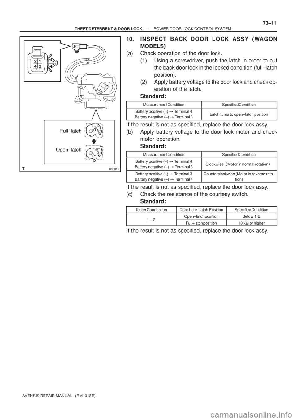
10. INSPECT BACK DOOR LOCK ASSY (WAGON
MODELS)
(a) Check operation of the door lock.
(1) Using a screwdriver, push the latch in order to put
the back door lock in the locked condition (full±latch
position).
(2) Apply battery voltage to the door lock and check op-
eration of the latch.
Standard:
Measurement ConditionSpecified Condition
Battery positive (+) � Terminal 4
Battery negative (±) � Terminal 3Latch turns to open±latch position
If the result is not as specified, replace the door lock assy.
(b) Apply battery voltage to the door lock motor and check
motor operation.
Standard:
Measurement ConditionSpecified Condition
Battery positive (+) � Terminal 4
Battery negative (±) � Terminal 3Clockwise�Motor in normal rotation�
Battery positive (+) � Terminal 3
Battery negative (±) � Terminal 4Counterclockwise (Motor in reverse rota-
tion)
If the result is not as specified, replace the door lock assy.
(c) Check the resistance of the courtesy switch.
Standard:
Tester ConnectionDoor Lock Latch PositionSpecified Condition
12Open±latch positionBelow 1 �1 ± 2Full±latch position10 k�or higher
If the result is not as specified, replace the door lock assy.
Page 3330 of 5135
B66816
Full±latch
Open±latch
B68460
LOCK
UNLOCK
Door Control Switch
123 6 745 8918 19 22 2320 21 24
10 11 14 15
12 13 16 17
73±12
± THEFT DETERRENT & DOOR LOCKPOWER DOOR LOCK CONTROL SYSTEM
AVENSIS REPAIR MANUAL (RM1018E)
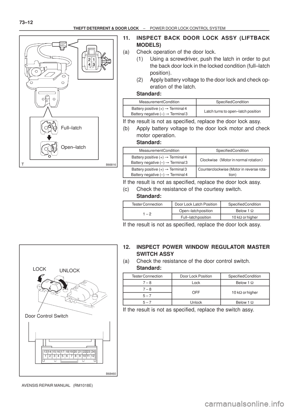
11. INSPECT BACK DOOR LOCK ASSY (LIFTBACK
MODELS)
(a) Check operation of the door lock.
(1) Using a screwdriver, push the latch in order to put
the back door lock in the locked condition (full±latch
position).
(2) Apply battery voltage to the door lock and check op-
eration of the latch.
Standard:
Measurement ConditionSpecified Condition
Battery positive (+) � Terminal 4
Battery negative (±) � Terminal 3Latch turns to open±latch position
If the result is not as specified, replace the door lock assy.
(b) Apply battery voltage to the door lock motor and check
motor operation.
Standard:
Measurement ConditionSpecified Condition
Battery positive (+) � Terminal 4
Battery negative (±) � Terminal 3Clockwise�Motor in normal rotation�
Battery positive (+) � Terminal 3
Battery negative (±) � Terminal 4Counterclockwise (Motor in reverse rota-
tion)
If the result is not as specified, replace the door lock assy.
(c) Check the resistance of the courtesy switch.
Standard:
Tester ConnectionDoor Lock Latch PositionSpecified Condition
12Open±latch positionBelow 1 �1 ± 2Full±latch position10 k�or higher
If the result is not as specified, replace the door lock assy.
12. INSPECT POWER WINDOW REGULATOR MASTER
SWITCH ASSY
(a) Check the resistance of the door control switch.
Standard:
Tester ConnectionDoor Lock PositionSpecified Condition
7 ± 8LockBelow 1 �
7 ± 8OFF10 k�or higher5 ± 7OFF10 k�or higher
5 ± 7UnlockBelow 1 �
If the result is not as specified, replace the switch assy.
Page 3331 of 5135
B68466
Pushed
Free
± THEFT DETERRENT & DOOR LOCKPOWER DOOR LOCK CONTROL SYSTEM
73±13
AVENSIS REPAIR MANUAL (RM1018E)
13. INSPECT BACK DOOR OPENER SWITCH ASSY
(a) Check the resistance of the switch.
Standard:
Tester ConnectionSwitch PositionSpecified Condition
12Free10 k�or higher1 ± 2PushedBelow 1 �
If the result is not as specified, replace the door lock assy.
Page 3332 of 5135
730GV±01
± THEFT DETERRENT & DOOR LOCKPOWER DOOR LOCK CONTROL SYSTEM
73±1
AVENSIS REPAIR MANUAL (RM1018E)
POWER DOOR LOCK CONTROL SYSTEM
ON±VEHICLE INSPECTION
1. DOOR LOCK FAIL±SAFE
(a) When a malfunction in the door control switch (manual switch, driver's door lock) has been detected,
door lock/unlock operation becomes disabled.
2. CHECK ELECTRICAL DOOR LOCK OPERATION
(a) Check the basic function.
(1) Check that all doors lock when the door control switch (for manual operation) is turned to LOCK
and all doors unlock when turned to UNLOCK.
(2) Check that all doors lock when the driver's door is locked from the outside using the key. Check
that all doors unlock when the driver's door is unlocked from the outside using the key.
(b) Check the key lock±in prevention function.
NOTICE:
In order to prevent the key from being locked in, the inspection should be made with the driver side
door glass open.
(1) Have the key inserted into the ignition key cylinder.
(2) With the driver side door open, check that all doors unlock immediately after the door lock knob
for the driver side door is turned to LOCK.
(3) With the driver side door open, check that all doors unlock immediately after the door control
switch (for manual operation) is turned to LOCK.
(4) With the driver side door open, turn the driver side door lock knob to LOCK and hold it for 2 se-
conds or more, and then close the driver side door. Then check that all doors unlock.
(c) Check the security function.
(1) Close all doors with the driver side door glass open so that the door control switch can be oper-
ated from outside the vehicle
(2) Pull out the key, open the driver side door and then close and lock the door without using the
key. Then, check that all doors do not unlock when the door control switch (for manual operation)
is turned to UNLOCK from outside the vehicle.
(3) Pull out the key, close and lock the driver side door by key operation. Under this condition, check
that all doors do not unlock when the door control switch (for manual operation) is turned to UN-
LOCK from outside the vehicle.
(4) Pull out the key, close the driver side door and lock the door by wireless door lock operation.
Then, check that all doors do not unlock when the door control switch (for manual operation) is
turned to UNLOCK from outside the vehicle.
HINT:
Check that the security function is canceled under the following conditions.
�The ignition switch is turned ON.
�The driver side door is unlocked using the key.
�The door control switch (for manual operation) is turned to UNLOCK after the door control knob is
turned to UNLOCK manually.
�The doors are unlocked with wireless operation.
Page 3333 of 5135
73±2
± THEFT DETERRENT & DOOR LOCKPOWER DOOR LOCK CONTROL SYSTEM
AVENSIS REPAIR MANUAL (RM1018E)
(d) Check the illumination function.
(1) Set the room light switch in the DOOR position.
(2) With all doors locked, check that all doors unlock when the driver side door lock cylinder is turned
to UNLOCK using the key and that the room right turns on.
(3) Check that the room light turns off in approx. 15 seconds after the doors have not been opened
for a while.
3. w/ Double lock:
CHECK DOUBLE LOCKING FUNCTION SYSTEM
(a) Check that the double locking system is set to ON.
(1) Open all the windows.
(2) Turn the ignition switch to LOCK and remove the key.
(3) Open and close the driver side door, and make sure that all doors including the back door are
closed securely.
(4) Push the LOCK switch on the wireless transmitter twice within 5 seconds, and check that the
hazard warning lights flash once at this time to show that the system is set.
(5) Try to unlock all doors using the inside handle of the vehicle, and check that none of the doors
unlock.
NOTICE:
�The double locking system cannot be set to ON without using the wireless transmitter.
�The double locking system operation is not related to the back door.
(b) Check that the double locking system is set to OFF.
(1) Push the UNLOCK switch on the wireless transmitter while the double locking system is ON, and
check that the hazard warning lights flash twice at this time to show that the system is set to OFF.
(2) Check that the doors can be opened both by the inside handle and the outside handle.
NOTICE:
If the battery of the wireless transmitter is dead, only the driver side door can be opened using the
key. However, the theft deterrent system still remains on. Therefore, be aware that the theft alarm
is set off when the door is opened without the use of the wireless transmitter.
Page 3338 of 5135
B66994
75±34
± ENGINE HOOD/DOORLUGGAGE COMPARTMENT DOOR
AVENSIS REPAIR MANUAL (RM1018E)
(e) Adjust the striker.
HINT:
Adjust the door lock position by moving the striker so that the
door striker can enter smoothly.
(1) Using a hammer and a brass bar, tap the striker to
adjust it.
(2) Tighten the 2 bolts after the adjustment.
Torque: 11.5 N�m (120 kgf�cm, 8 ft�lbf)
Page 3339 of 5135
750N1±01
B66985
Luggage Compartment
Door Panel Sub±assy
Luggage Compartment
Outside Garnish
Licence Plate Lamp Assy Luggage Compartment Door Lock Cylinder Assy
Luggage Compartment Trim Hook No. 2
Rear Floor Finish Plate
Luggage Striker Assy
Rope Hook AssyBack Door Trim Cover
Luggage Compartment Floor CarpetLuggage Compartment
Trim Inner RH
Luggage Compartment
Trim Inner LHLuggage Lock Assy
Clip
4.9 (49, 43 in.´lbf)
5.0 (51, 44 in.´lbf)
5.0 (51, 44 in.´lbf)
Hinge Cover
: Specified torqueN´m (kgf´cm, ft´lbf)
7.0 (71, 62 in.´lbf)
11.5 (120, 8)
75±32
± ENGINE HOOD/DOORLUGGAGE COMPARTMENT DOOR
AVENSIS REPAIR MANUAL (RM1018E)
LUGGAGE COMPARTMENT DOOR
COMPONENTS
Page 3343 of 5135
B66980
B66983
B62438
B57767
± ENGINE HOOD/DOORREAR DOOR
75±25
AVENSIS REPAIR MANUAL (RM1018E)
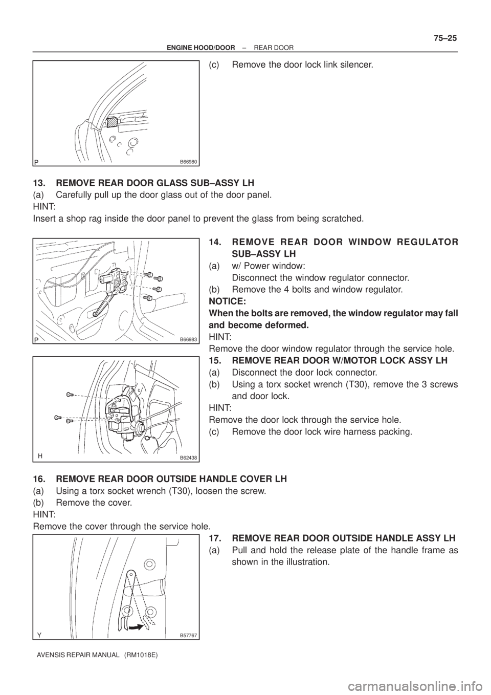
(c) Remove the door lock link silencer.
13. REMOVE REAR DOOR GLASS SUB±ASSY LH
(a) Carefully pull up the door glass out of the door panel.
HINT:
Insert a shop rag inside the door panel to prevent the glass from being scratched.
14. REMOVE REAR DOOR WINDOW REGULATOR
SUB±ASSY LH
(a) w/ Power window:
Disconnect the window regulator connector.
(b) Remove the 4 bolts and window regulator.
NOTICE:
When the bolts are removed, the window regulator may fall
and become deformed.
HINT:
Remove the door window regulator through the service hole.
15. REMOVE REAR DOOR W/MOTOR LOCK ASSY LH
(a) Disconnect the door lock connector.
(b) Using a torx socket wrench (T30), remove the 3 screws
and door lock.
HINT:
Remove the door lock through the service hole.
(c) Remove the door lock wire harness packing.
16. REMOVE REAR DOOR OUTSIDE HANDLE COVER LH
(a) Using a torx socket wrench (T30), loosen the screw.
(b) Remove the cover.
HINT:
Remove the cover through the service hole.
17. REMOVE REAR DOOR OUTSIDE HANDLE ASSY LH
(a) Pull and hold the release plate of the handle frame as
shown in the illustration.