Page 1626 of 5135
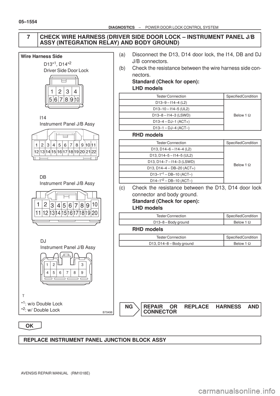
B70498
D13*1, D14*2
Driver Side Door Lock Wire Harness Side
I14
Instrument Panel J/B Assy
*
1: w/o Double Lock
*2: w/ Double LockDB
Instrument Panel J/B Assy
DJ
Instrument Panel J/B Assy
56 12
783
49
05±1554
± DIAGNOSTICSPOWER DOOR LOCK CONTROL SYSTEM
AVENSIS REPAIR MANUAL (RM1018E)
7 CHECK WIRE HARNESS (DRIVER SIDE DOOR LOCK ± INSTRUMENT PANEL J/B
ASSY (INTEGRATION RELAY) AND BODY GROUND)
(a) Disconnect the D13, D14 door lock, the I14, DB and DJ
J/B connectors.
(b) Check the resistance between the wire harness side con-
nectors.
Standard (Check for open):
LHD models
Tester ConnectionSpecified Condition
D13±9 ± I14±4 (L2)
D13±10 ± I14±5 (UL2)
D13±8 ± I14±3 (LSWD)Below 1 �
D13±4 ± DJ±1 (ACT+)
D13±1 ± DJ±4 (ACT±)
RHD models
Tester ConnectionSpecified Condition
D13, D14±6 ± I14±4 (L2)
D13, D14±5 ± I14±5 (UL2)
D13, D14±7 ± I14±3 (LSWD)Below 1�D13, D14±4 ± DB±20 (ACT+)Below 1 �
D13±1*1 ± DB±10 (ACT±)
D14±1*2 ± DB±10 (ACT±)
(c) Check the resistance between the D13, D14 door lock
connector and body ground.
Standard (Check for open):
LHD models
Tester ConnectionSpecified Condition
D13±8 ± Body groundBelow 1 �
RHD models
Tester ConnectionSpecified Condition
D13, D14±8 ± Body groundBelow 1 �
NG REPAIR OR REPLACE HARNESS AND
CONNECTOR
OK
REPLACE INSTRUMENT PANEL JUNCTION BLOCK ASSY
Page 1627 of 5135
05C8A±01
±
DIAGNOSTICS POWER DOOR LOCK CONTROL SYSTEM
05±1545
AVENSIS REPAIR MANUAL (RM1018E)
PROBLEM SYMPTOMS TABLE
SymptomSuspected AreaSee Page
All doors cannot be locked/unlocked at once
3. DOOR fuse
4. ECU±B 2 fuse
5. Power window regulator master switch assy
6. Front door lock assy LH, RH (Driver side)
7. Instrument panel J/B assy (Integration relay)
8. Wire harness
05±1546
Key lock±in prevention function does not work properly (Manual
operation and operation interlocked with key are active)
1. Unlock warning switch assy
2. Courtesy lamp switch assy LH, RH (Driver side)
3. Instrument panel J/B assy (Integration relay)
4. Wire harness
05±1555
w/ Double lock:
Double lock function does not operate properly
1. Wireless system
2. DOOR fuse
3. ECU±B 2 fuse
4. Front door lock assy LH, RH
5. Rear door lock assy LH, RH
6. Instrument panel J/B assy (Integration relay)
7. Wire harness
05±1560
Page 1628 of 5135
05C89±01
B70502
DADBDM
Vehicle Front Side Vehicle Rear Side
DB
DA
DHDC
I14
DN
DC
DH
I14
DM
DN
Integration Relay
DJ
DJ
05±1542
± DIAGNOSTICSPOWER DOOR LOCK CONTROL SYSTEM
AVENSIS REPAIR MANUAL (RM1018E)
TERMINALS OF ECU
1. CHECK INSTRUMENT PANEL J/B ASSY (INTEGRATION RELAY)
Page 1629 of 5135
± DIAGNOSTICSPOWER DOOR LOCK CONTROL SYSTEM
05±1543
AVENSIS REPAIR MANUAL (RM1018E)
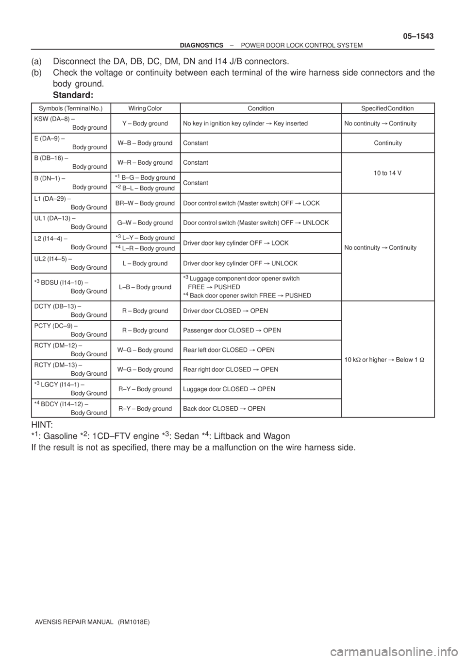
(a) Disconnect the DA, DB, DC, DM, DN and I14 J/B connectors.
(b) Check the voltage or continuity between each terminal of the wire harness side connectors and the
body ground.
Standard:
Symbols (Terminal No.)Wiring ColorConditionSpecified Condition
KSW (DA±8) ±
Body groundY ± Body groundNo key in ignition key cylinder � Key insertedNo continuity � Continuity
E (DA±9) ±
Body groundW±B ± Body groundConstantContinuity
B (DB±16) ±
Body groundW±R ± Body groundConstant
10 to 14 VB (DN±1) ± *1
B±G ± Body groundConstant
10 to 14 VB (DN 1)
Body ground
*2
B±L ± Body groundConstant
L1 (DA±29) ±
Body GroundBR±W ± Body groundDoor control switch (Master switch) OFF � LOCK
UL1 (DA±13) ±
Body GroundG±W ± Body groundDoor control switch (Master switch) OFF � UNLOCK
L2 (I14±4) ± *3
L±Y ± Body groundDriver door key cylinder OFF�LOCKL2 (I14 4)
Body Ground
*4
L±R ± Body groundDriver door key cylinder OFF � LOCKNo continuity � Continuity
UL2 (I14±5) ±
Body GroundL ± Body groundDriver door key cylinder OFF � UNLOCK
yy
*3 BDSU (I14±10) ±
Body GroundL±B ± Body ground
*3 Luggage component door opener switch
FREE � PUSHED
*
4 Back door opener switch FREE � PUSHED
DCTY (DB±13) ±
Body GroundR ± Body groundDriver door CLOSED � OPEN
PCTY (DC±9) ±
Body GroundR ± Body groundPassenger door CLOSED � OPEN
RCTY (DM±12) ±
Body GroundW±G ± Body groundRear left door CLOSED � OPEN
10 k�or higher�Below 1�RCTY (DM±13) ±
Body GroundW±G ± Body groundRear right door CLOSED � OPEN
10 k� or higher � Below 1 �
*3 LGCY (I14±1) ±
Body GroundR±Y ± Body groundLuggage door CLOSED � OPEN
*4 BDCY (I14±12) ±
Body GroundR±Y ± Body groundBack door CLOSED � OPEN
HINT:
*
1: Gasoline *2: 1CD±FTV engine *3: Sedan *4: Liftback and Wagon
If the result is not as specified, there may be a malfunction on the wire harness side.
Page 1630 of 5135
05±1544
± DIAGNOSTICSPOWER DOOR LOCK CONTROL SYSTEM
AVENSIS REPAIR MANUAL (RM1018E)
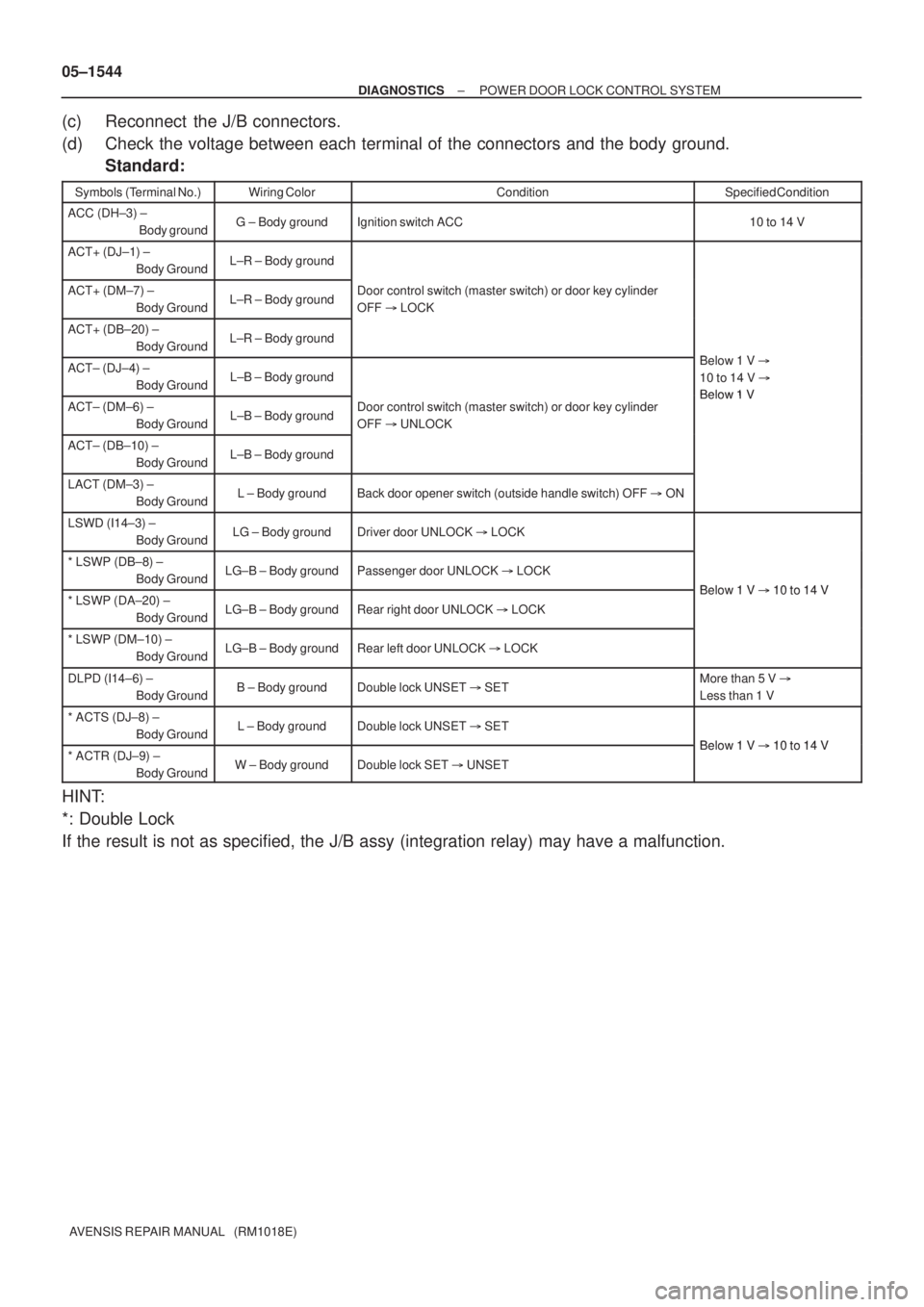
(c) Reconnect the J/B connectors.
(d) Check the voltage between each terminal of the connectors and the body ground.
Standard:
Symbols (Terminal No.)Wiring ColorConditionSpecified Condition
ACC (DH±3) ±
Body groundG ± Body groundIgnition switch ACC10 to 14 V
ACT+ (DJ±1) ±
Body GroundL±R ± Body ground
ACT+ (DM±7) ±
Body GroundL±R ± Body groundDoor control switch (master switch) or door key cylinder
OFF � LOCK
ACT+ (DB±20) ±
Body GroundL±R ± Body ground
Bl 1VACT± (DJ±4) ±
Body GroundL±B ± Body ground
Below 1 V �
10 to 14 V �
Below 1 VACT± (DM±6) ±
Body GroundL±B ± Body groundDoor control switch (master switch) or door key cylinder
OFF � UNLOCKBelow 1 V
ACT± (DB±10) ±
Body GroundL±B ± Body ground
LACT (DM±3) ±
Body GroundL ± Body groundBack door opener switch (outside handle switch) OFF � ON
LSWD (I14±3) ±
Body GroundLG ± Body groundDriver door UNLOCK � LOCK
* LSWP (DB±8) ±
Body GroundLG±B ± Body groundPassenger door UNLOCK � LOCK
Below 1 V�10 to 14 V* LSWP (DA±20) ±
Body GroundLG±B ± Body groundRear right door UNLOCK � LOCK
Below 1 V � 10 to 14 V
* LSWP (DM±10) ±
Body GroundLG±B ± Body groundRear left door UNLOCK � LOCK
DLPD (I14±6) ±
Body GroundB ± Body groundDouble lock UNSET � SETMore than 5 V �
Less than 1 V
* ACTS (DJ±8) ±
Body GroundL ± Body groundDouble lock UNSET � SET
Below 1 V�10 to 14 V* ACTR (DJ±9) ±
Body GroundW ± Body groundDouble lock SET � UNSET
Below 1 V � 10 to 14 V
HINT:
*: Double Lock
If the result is not as specified, the J/B assy (integration relay) may have a malfunction.
Page 1645 of 5135
B68159
17
DB
DCTY
KSW R B J/C
Combination Meter Assy
IC119
I14 11 DA Y
I14 22
P±B 12 1
W±B*
3
A1310
29*6
Buzzer
Meter ECU
20*
7
U1
Unlock Warning
Switch AssyIntegration Relay
B D9*
4
D10*5
Door Courtesy Lamp Switch
(Driver Side)
W±B
IC1
P
*
1: 1AZ±FSE
*2: 1AZ±FE, 1ZZ±FE, 3ZZ±FE
*
3: 1CD±FTV
*
4: LHD
*5: RHD
*
6: Except Automatic A/C
*7: Automatic A/CMPX2 Instrument Panel J/B
13
J10 J10CE CA1
5
R RIC2 IM1914
8 W±B*
5CF CA13
6
MPX1 P±B
C1014 1
A15
MPX±
MPX+
A13
A159*
6
10*7
P
P±B A/C Control
Assembly
E10 E9 E9212929
E10 E9 E9 202318ECM
*
1*1*2*3*2*3
*5*4
R*5
R*4
Center J/B
Center J/B
C10 13
PR
IPIL W±B*
4A
AJ16
IO W±B*
1,
2
R*5
W±B*5
05±1594
± DIAGNOSTICSKEY REMINDER WARNING SYSTEM
AVENSIS REPAIR MANUAL (RM1018E)
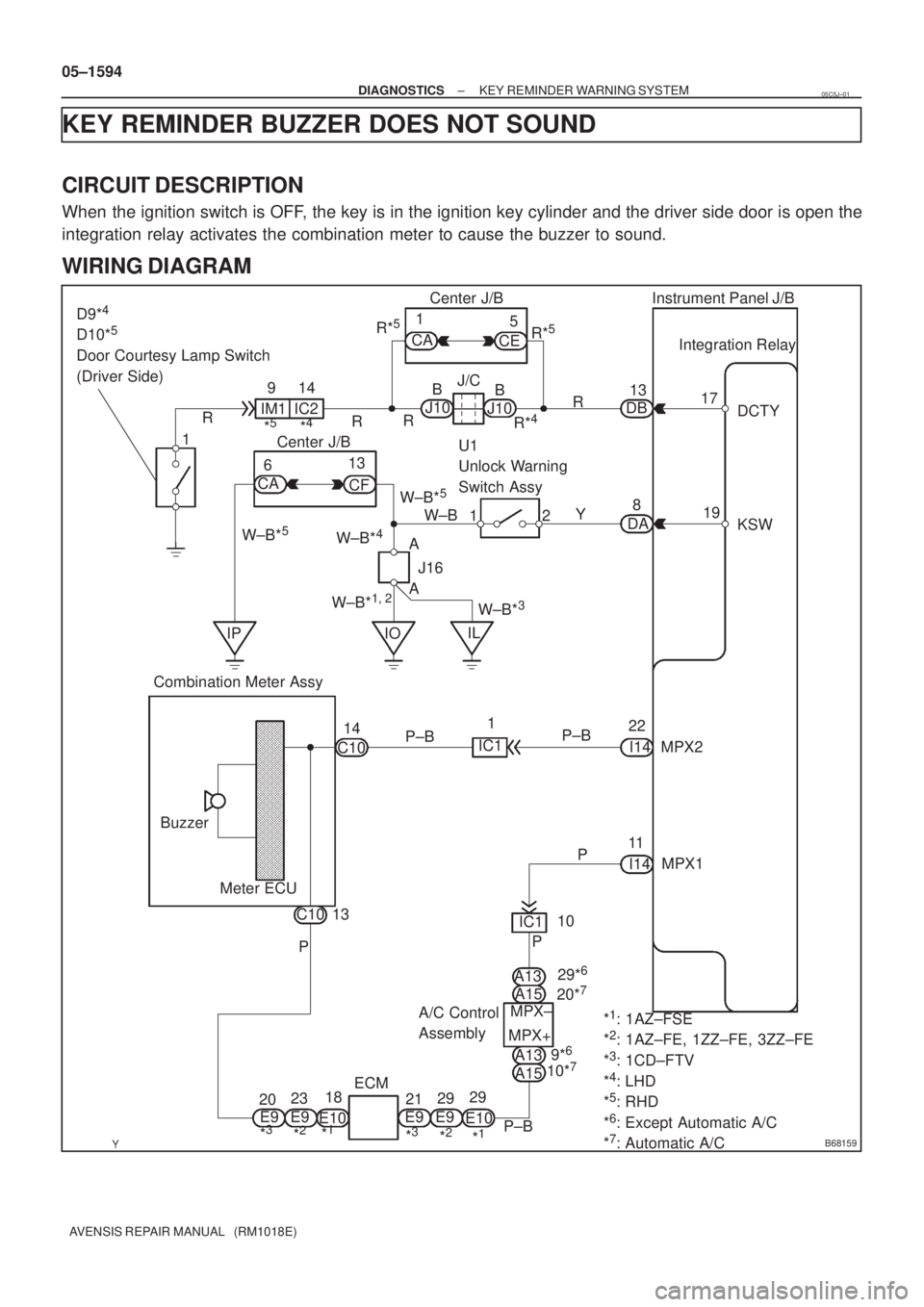
KEY REMINDER BUZZER DOES NOT SOUND
CIRCUIT DESCRIPTION
When the ignition switch is OFF, the key is in the ignition key cylinder and the driver side door is open the
integration relay activates the combination meter to cause the buzzer to sound.
WIRING DIAGRAM
05C5J±01
Page 1647 of 5135
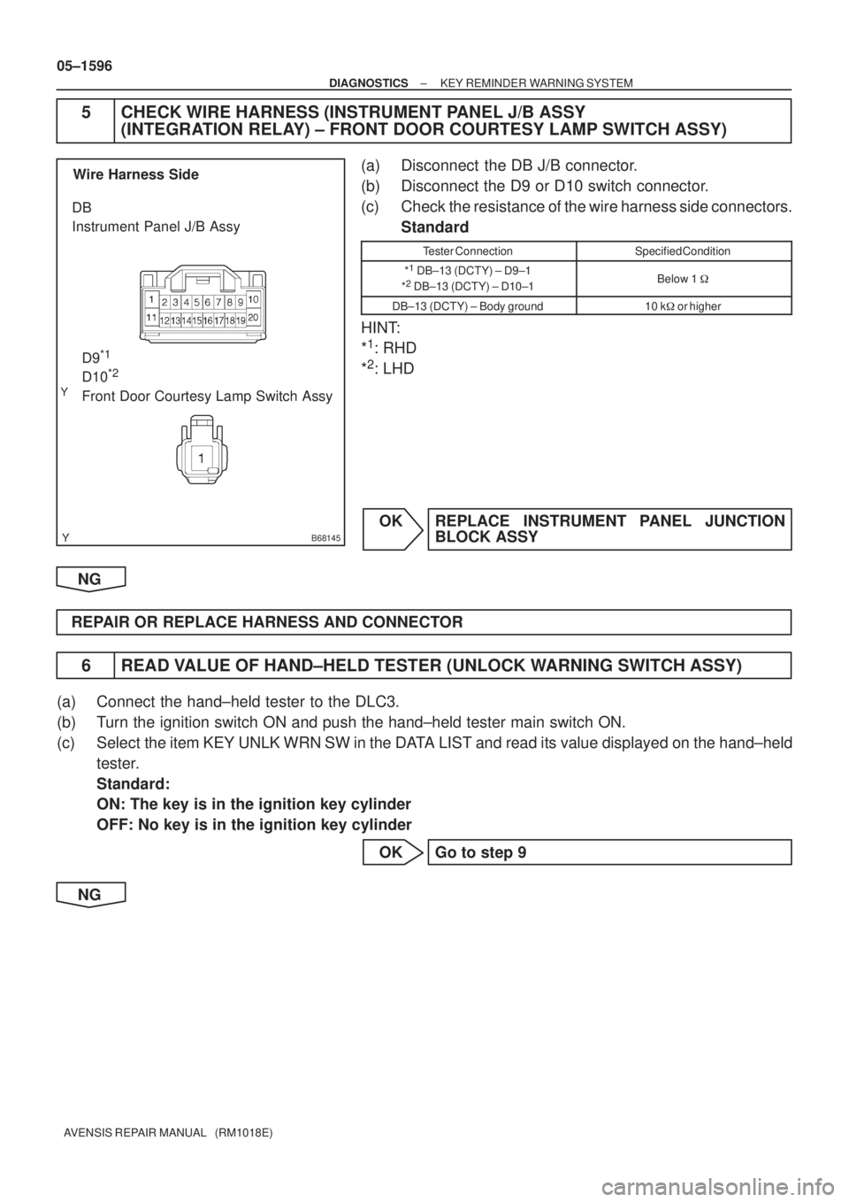
B68145
D9*1
D10*2
Front Door Courtesy Lamp Switch Assy DB
Instrument Panel J/B AssyWire Harness Side
05±1596
± DIAGNOSTICSKEY REMINDER WARNING SYSTEM
AVENSIS REPAIR MANUAL (RM1018E)
5 CHECK WIRE HARNESS (INSTRUMENT PANEL J/B ASSY
(INTEGRATION RELAY) ± FRONT DOOR COURTESY LAMP SWITCH ASSY)
(a) Disconnect the DB J/B connector.
(b) Disconnect the D9 or D10 switch connector.
(c) Check the resistance of the wire harness side connectors.
Standard
Tester ConnectionSpecified Condition
*1
DB±13 (DCTY) ± D9±1
*2
DB±13 (DCTY) ± D10±1Below 1 �
DB±13 (DCTY) ± Body ground10 k�or higher
HINT:
*
1: RHD
*
2: LHD
OK REPLACE INSTRUMENT PANEL JUNCTION
BLOCK ASSY
NG
REPAIR OR REPLACE HARNESS AND CONNECTOR
6 READ VALUE OF HAND±HELD TESTER (UNLOCK WARNING SWITCH ASSY)
(a) Connect the hand±held tester to the DLC3.
(b) Turn the ignition switch ON and push the hand±held tester main switch ON.
(c) Select the item KEY UNLK WRN SW in the DATA LIST and read its value displayed on the hand±held
tester.
Standard:
ON: The key is in the ignition key cylinder
OFF: No key is in the ignition key cylinder
OK Go to step 9
NG
Page 1650 of 5135
05AF2±02
±
DIAGNOSTICS KEY REMINDER WARNING SYSTEM
05±1593
AVENSIS REPAIR MANUAL (RM1018E)
PROBLEM SYMPTOMS TABLE
SymptomSuspected AreaSee Page
Key reminder buzzer does not sound
1. Unlock warning switch assy
2. Front door courtesy lamp switch (Driver side)
3. Instrument panel junction block assy (Integration relay)
4. Combination meter
5. Wire harness05±1594
05±1594
05±1591
±
±