Page 3427 of 5135
B66529
ClawClaw
B50596
90�
B66556
Clip
w/ Sliding Roof
w/o Sliding Roof 76±40
± EXTERIOR/INTERIOR TRIMROOF HEADLINING ASSY (SEDAN MODELS)
AVENSIS REPAIR MANUAL (RM1018E)
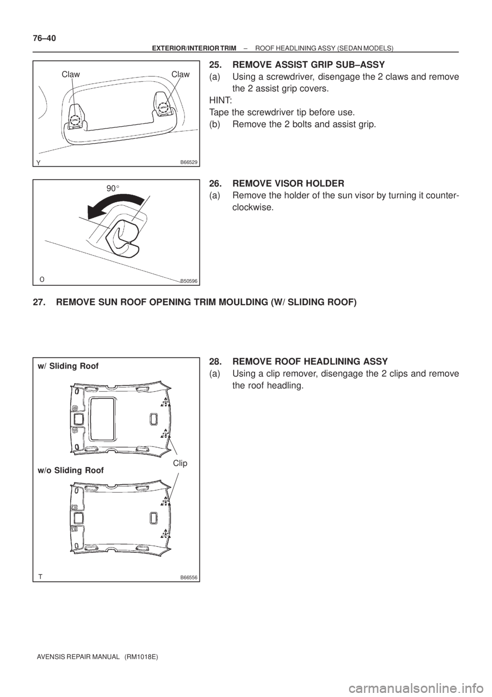
25. REMOVE ASSIST GRIP SUB±ASSY
(a) Using a screwdriver, disengage the 2 claws and remove
the 2 assist grip covers.
HINT:
Tape the screwdriver tip before use.
(b) Remove the 2 bolts and assist grip.
26. REMOVE VISOR HOLDER
(a) Remove the holder of the sun visor by turning it counter-
clockwise.
27. REMOVE SUN ROOF OPENING TRIM MOULDING (W/ SLIDING ROOF)
28. REMOVE ROOF HEADLINING ASSY
(a) Using a clip remover, disengage the 2 clips and remove
the roof headling.
Page 3455 of 5135
A79919
Claw
Claw
B66541Claw
Claw
B66529
ClawClaw
B50596
90�
± EXTERIOR/INTERIOR TRIMROOF HEADLINING ASSY (WAGON MODELS)
76±59
AVENSIS REPAIR MANUAL (RM1018E)
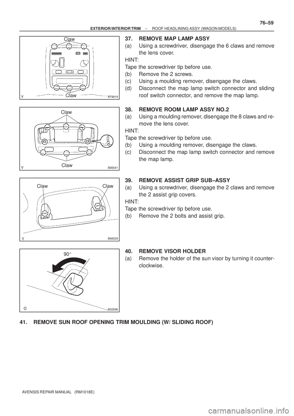
37. REMOVE MAP LAMP ASSY
(a) Using a screwdriver, disengage the 6 claws and remove
the lens cover.
HINT:
Tape the screwdriver tip before use.
(b) Remove the 2 screws.
(c) Using a moulding remover, disengage the claws.
(d) Disconnect the map lamp switch connector and sliding
roof switch connector, and remove the map lamp.
38. REMOVE ROOM LAMP ASSY NO.2
(a) Using a moulding remover, disengage the 8 claws and re-
move the lens cover.
HINT:
Tape the screwdriver tip before use.
(b) Using a moulding remover, disengage the claws.
(c) Disconnect the map lamp switch connector and remove
the map lamp.
39. REMOVE ASSIST GRIP SUB±ASSY
(a) Using a screwdriver, disengage the 2 claws and remove
the 2 assist grip covers.
HINT:
Tape the screwdriver tip before use.
(b) Remove the 2 bolts and assist grip.
40. REMOVE VISOR HOLDER
(a) Remove the holder of the sun visor by turning it counter-
clockwise.
41. REMOVE SUN ROOF OPENING TRIM MOULDING (W/ SLIDING ROOF)
Page 3471 of 5135
A82647
Length
A82648
No Continuity
A82649
Free Lock
A82650
Apply Grease
A82651
± STARTING & CHARGINGSTARTER ASSY
19±5
1AZ±FSE ENGINE REPAIR MANUAL (RM1019E)
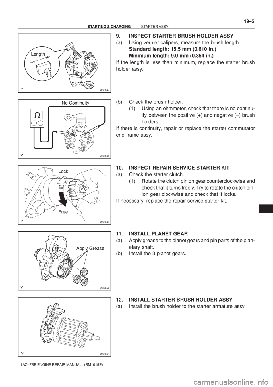
9. INSPECT STARTER BRUSH HOLDER ASSY
(a) Using vernier calipers, measure the brush length.
Standard length: 15.5 mm (0.610 in.)
Minimum length: 9.0 mm (0.354 in.)
If the length is less than minimum, replace the starter brush
holder assy.
(b) Check the brush holder.
(1) Using an ohmmeter, check that there is no continu-
ity between the positive (+) and negative (±) brush
holders.
If there is continuity, repair or replace the starter commutator
end frame assy.
10. INSPECT REPAIR SERVICE STARTER KIT
(a) Check the starter clutch.
(1) Rotate the clutch pinion gear counterclockwise and
check that it turns freely. Try to rotate the clutch pin-
ion gear clockwise and check that it locks.
If necessary, replace the repair service starter kit.
11. INSTALL PLANET GEAR
(a) Apply grease to the planet gears and pin parts of the plan-
etary shaft.
(b) Install the 3 planet gears.
12. INSTALL STARTER BRUSH HOLDER ASSY
(a) Install the brush holder to the starter armature assy.
Page 3507 of 5135
190OK±01
A80108
B09748
B09749
B09750
± STARTING & CHARGINGGENERATOR ASSY
19±9
1AZ±FSE ENGINE REPAIR MANUAL (RM1019E)
OVERHAUL
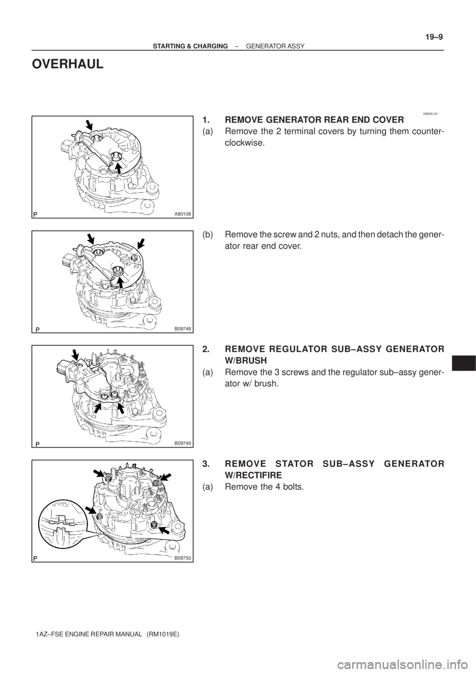
1. REMOVE GENERATOR REAR END COVER
(a) Remove the 2 terminal covers by turning them counter-
clockwise.
(b) Remove the screw and 2 nuts, and then detach the gener-
ator rear end cover.
2. REMOVE REGULATOR SUB±ASSY GENERATOR
W/BRUSH
(a) Remove the 3 screws and the regulator sub±assy gener-
ator w/ brush.
3. REMOVE STATOR SUB±ASSY GENERATOR
W/RECTIFIRE
(a) Remove the 4 bolts.
Page 3587 of 5135
9808U±01
± COMPONENTS151350
98±7
3510/PLANETARY GEAR, REVERSE PISTON & COUNTER
GEAR(ATM)
(0008± )NZE121..ATM U340E
Page 3596 of 5135
C68188
D25174
SST
D25175
SST
D25176
SST
± AUTOMATIC TRANSMISSION / TRANSFRONNT DIFFERENTIAL ASSY (U34#E Series)
40±73
U340E A/T REPAIR MANUAL (RM824E)
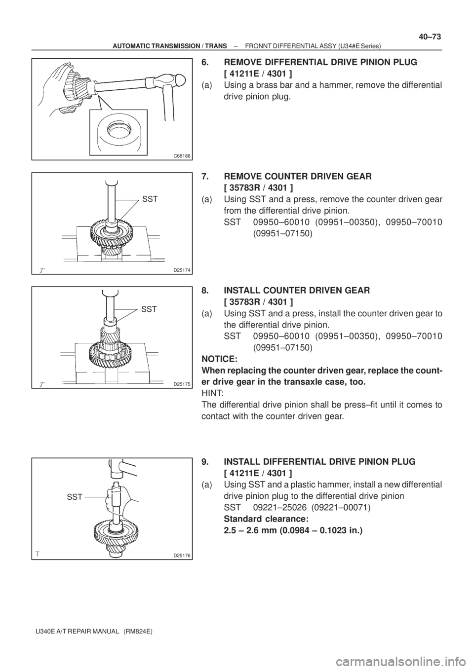
6. REMOVE DIFFERENTIAL DRIVE PINION PLUG
[ 41211E / 4301 ]
(a) Using a brass bar and a hammer, remove the differential
drive pinion plug.
7. REMOVE COUNTER DRIVEN GEAR
[ 35783R / 4301 ]
(a) Using SST and a press, remove the counter driven gear
from the differential drive pinion.
SST 09950±60010 (09951±00350), 09950±70010
(09951±07150)
8. INSTALL COUNTER DRIVEN GEAR
[ 35783R / 4301 ]
(a) Using SST and a press, install the counter driven gear to
the differential drive pinion.
SST 09950±60010 (09951±00350), 09950±70010
(09951±07150)
NOTICE:
When replacing the counter driven gear, replace the count-
er drive gear in the transaxle case, too.
HINT:
The differential drive pinion shall be press±fit until it comes to
contact with the counter driven gear.
9. INSTALL DIFFERENTIAL DRIVE PINION PLUG
[ 41211E / 4301 ]
(a) Using SST and a plastic hammer, install a new differential
drive pinion plug to the differential drive pinion
SST 09221±25026 (09221±00071)
Standard clearance:
2.5 ± 2.6 mm (0.0984 ± 0.1023 in.)
Page 3620 of 5135
D03689
SST
SST
D03690
SST
D03691
SST SST
D03826
D03827
± AUTOMATIC TRANSMISSION / TRANSUNDERDRIVE PLANETARY GEAR ASSY (U241E)
40±93
U241E A/T REPAIR MANUAL (RM840U)
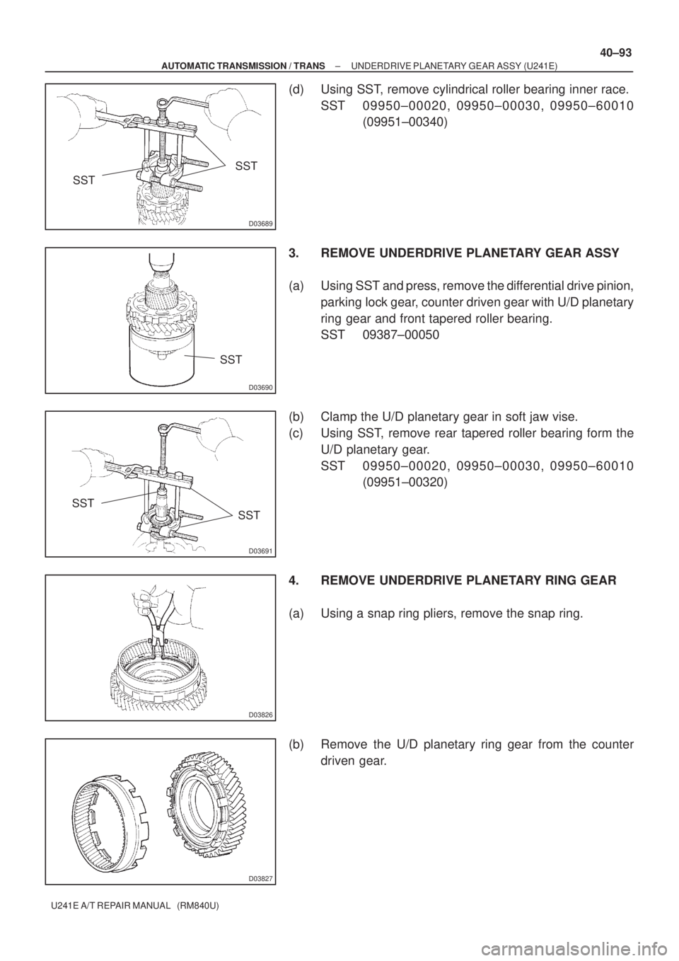
(d) Using SST, remove cylindrical roller bearing inner race.
SST 09950±00020, 09950±00030, 09950±60010
(09951±00340)
3. REMOVE UNDERDRIVE PLANETARY GEAR ASSY
(a) Using SST and press, remove the differential drive pinion,
parking lock gear, counter driven gear with U/D planetary
ring gear and front tapered roller bearing.
SST 09387±00050
(b) Clamp the U/D planetary gear in soft jaw vise.
(c) Using SST, remove rear tapered roller bearing form the
U/D planetary gear.
SST 09950±00020, 09950±00030, 09950±60010
(09951±00320)
4. REMOVE UNDERDRIVE PLANETARY RING GEAR
(a) Using a snap ring pliers, remove the snap ring.
(b) Remove the U/D planetary ring gear from the counter
driven gear.
Page 3621 of 5135
D08112
D08113
D08114
SST
SST
D03827
D03826
40±94
± AUTOMATIC TRANSMISSION / TRANSUNDERDRIVE PLANETARY GEAR ASSY (U241E)
U241E A/T REPAIR MANUAL (RM840U)
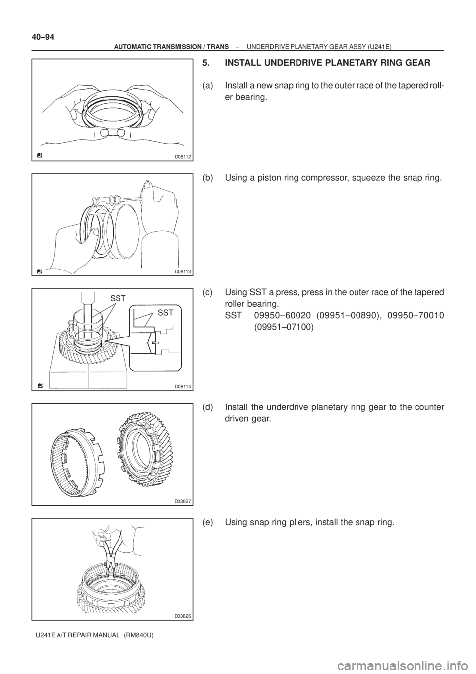
5. INSTALL UNDERDRIVE PLANETARY RING GEAR
(a) Install a new snap ring to the outer race of the tapered roll-
er bearing.
(b) Using a piston ring compressor, squeeze the snap ring.
(c) Using SST a press, press in the outer race of the tapered
roller bearing.
SST 09950±60020 (09951±00890), 09950±70010
(09951±07100)
(d) Install the underdrive planetary ring gear to the counter
driven gear.
(e) Using snap ring pliers, install the snap ring.