A62178
Push
A93670
A30848
A30857
A62814
4 2531
– ENGINE MECHANICALCYLINDER HEAD GASKET (1ZZ–FE/3ZZ–FE)(From
February, 2004)14–37
AVENSIS REPAIR MANUAL SUPPLEMENT
(RM1098E)
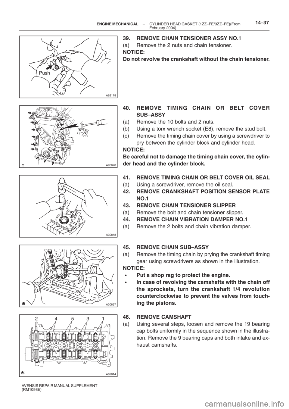
39. REMOVE CHAIN TENSIONER ASSY NO.1
(a) Remove the 2 nuts and chain tensioner.
NOTICE:
Do not revolve the crankshaft without the chain tensioner.
40. REMOVE TIMING CHAIN OR BELT COVER
SUB–ASSY
(a) Remove the 10 bolts and 2 nuts.
(b) Using a torx wrench socket (E8), remove the stud bolt.
(c) Remove the timing chain cover by using a screwdriver to
pry between the cylinder block and cylinder head.
NOTICE:
Be careful not to damage the timing chain cover, the cylin-
der head and the cylinder block.
41. REMOVE TIMING CHAIN OR BELT COVER OIL SEAL
(a) Using a screwdriver, remove the oil seal.
42. REMOVE CRANKSHAFT POSITION SENSOR PLATE
NO.1
43. REMOVE CHAIN TENSIONER SLIPPER
(a) Remove the bolt and chain tensioner slipper.
44. REMOVE CHAIN VIBRATION DAMPER NO.1
(a) Remove the 2 bolts and chain vibration damper.
45. REMOVE CHAIN SUB–ASSY
(a) Remove the timing chain by prying the crankshaft timing
gear using screwdrivers as shown in the illustration.
NOTICE:
�Put a shop rag to protect the engine.
�In case of revolving the camshafts with the chain off
the sprockets, turn the crankshaft 1/4 revolution
counterclockwise to prevent the valves from touch-
ing the pistons.
46. REMOVE CAMSHAFT
(a) Using several steps, loosen and remove the 19 bearing
cap bolts uniformly in the sequence shown in the illustra-
tion. Remove the 9 bearing caps and both intake and ex-
haust camshafts.
A62837SST
A62180
Disconnect
Hook
Pin Turn
A62181
Plunger
Turn
Push
A62182
Seal Packing
– ENGINE MECHANICALCYLINDER HEAD GASKET (1ZZ–FE/3ZZ–FE)(From
February, 2004)14–43
AVENSIS REPAIR MANUAL SUPPLEMENT
(RM1098E)
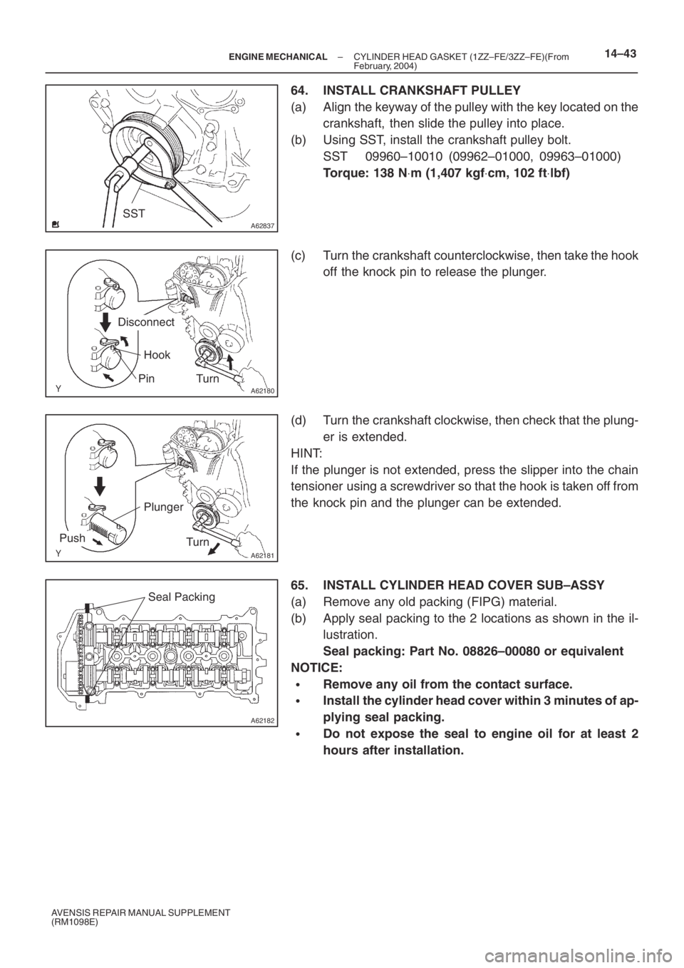
64. INSTALL CRANKSHAFT PULLEY
(a) Align the keyway of the pulley with the key located on the
crankshaft, then slide the pulley into place.
(b) Using SST, install the crankshaft pulley bolt.
SST 09960–10010 (09962–01000, 09963–01000)
Torque: 138 N⋅m (1,407 kgf⋅cm, 102 ft⋅lbf)
(c) Turn the crankshaft counterclockwise, then take the hook
off the knock pin to release the plunger.
(d) Turn the crankshaft clockwise, then check that the plung-
er is extended.
HINT:
If the plunger is not extended, press the slipper into the chain
tensioner using a screwdriver so that the hook is taken off from
the knock pin and the plunger can be extended.
65. INSTALL CYLINDER HEAD COVER SUB–ASSY
(a) Remove any old packing (FIPG) material.
(b) Apply seal packing to the 2 locations as shown in the il-
lustration.
Seal packing: Part No. 08826–00080 or equivalent
NOTICE:
�Remove any oil from the contact surface.
�Install the cylinder head cover within 3 minutes of ap-
plying seal packing.
�Do not expose the seal to engine oil for at least 2
hours after installation.