Page 2591 of 5135
320VI±01
G23173
Stop Lamp Switch Assy
Push Rod
Pedal Height
F43108
Stop Lamp Switch Assy Cushion
1.5 ± 2.5 mm (0.059 ± 0.098 in.) 32±6
± BRAKEBRAKE PEDAL SUB±ASSY
AVENSIS REPAIR MANUAL (RM1018E)
BRAKE PEDAL SUB±ASSY
ADJUSTMENT
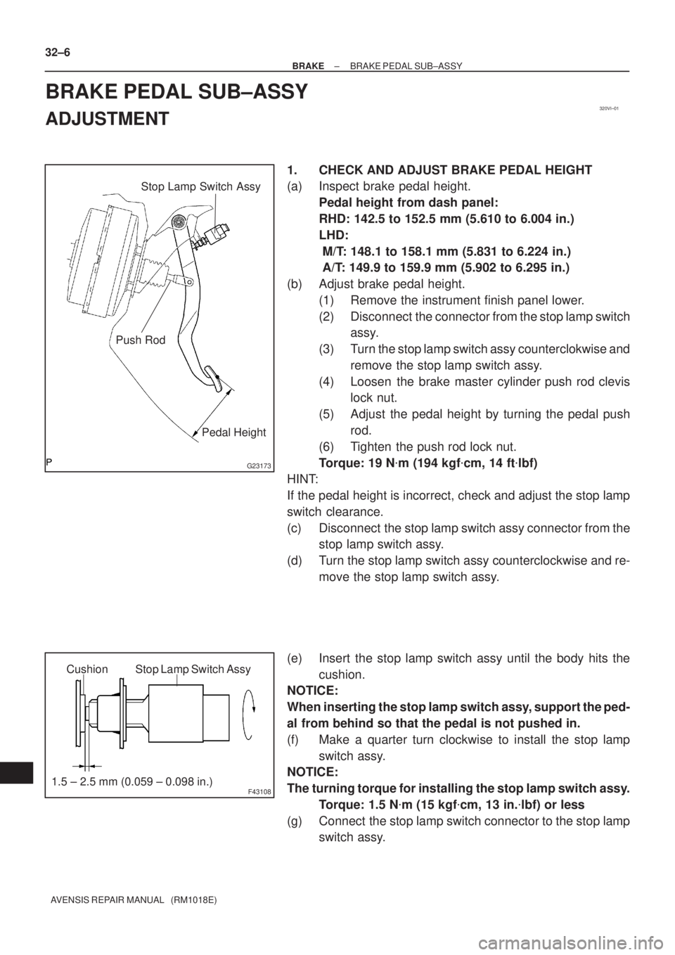
1. CHECK AND ADJUST BRAKE PEDAL HEIGHT
(a) Inspect brake pedal height.
Pedal height from dash panel:
RHD: 142.5 to 152.5 mm (5.610 to 6.004 in.)
LHD:
M/T: 148.1 to 158.1 mm (5.831 to 6.224 in.)
A/T: 149.9 to 159.9 mm (5.902 to 6.295 in.)
(b) Adjust brake pedal height.
(1) Remove the instrument finish panel lower.
(2) Disconnect the connector from the stop lamp switch
assy.
(3) Turn the stop lamp switch assy counterclokwise and
remove the stop lamp switch assy.
(4) Loosen the brake master cylinder push rod clevis
lock nut.
(5) Adjust the pedal height by turning the pedal push
rod.
(6) Tighten the push rod lock nut.
Torque: 19 N�m (194 kgf�cm, 14 ft�lbf)
HINT:
If the pedal height is incorrect, check and adjust the stop lamp
switch clearance.
(c) Disconnect the stop lamp switch assy connector from the
stop lamp switch assy.
(d) Turn the stop lamp switch assy counterclockwise and re-
move the stop lamp switch assy.
(e) Insert the stop lamp switch assy until the body hits the
cushion.
NOTICE:
When inserting the stop lamp switch assy, support the ped-
al from behind so that the pedal is not pushed in.
(f) Make a quarter turn clockwise to install the stop lamp
switch assy.
NOTICE:
The turning torque for installing the stop lamp switch assy.
Torque: 1.5 N�m (15 kgf�cm, 13 in.�lbf) or less
(g) Connect the stop lamp switch connector to the stop lamp
switch assy.
Page 2628 of 5135
320W2±01
G24251
Vacuum Hose
Oil Hose
F45364
F08966
F08967
± BRAKEVACUUM PUMP ASSY (1CD±FTV)
32±35
AVENSIS REPAIR MANUAL (RM1018E)
OVERHAUL
1. REMOVE AIR CLEANER CAP SUB±ASSY
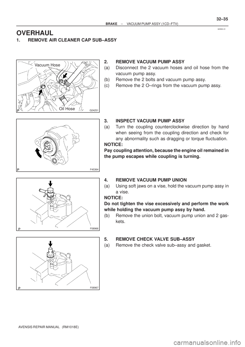
2. REMOVE VACUUM PUMP ASSY
(a) Disconnect the 2 vacuum hoses and oil hose from the
vacuum pump assy.
(b) Remove the 2 bolts and vacuum pump assy.
(c) Remove the 2 O±rings from the vacuum pump assy.
3. INSPECT VACUUM PUMP ASSY
(a) Turn the coupling counterclockwise direction by hand
when seeing from the coupling direction and check for
any abnormality such as dragging or torque fluctuation.
NOTICE:
Pay coupling attention, because the engine oil remained in
the pump escapes while coupling is turning.
4. REMOVE VACUUM PUMP UNION
(a) Using soft jaws on a vise, hold the vacuum pump assy in
a vise.
NOTICE:
Do not tighten the vise excessively and perform the work
while holding the vacuum pump assy by hand.
(b) Remove the union bolt, vacuum pump union and 2 gas-
kets.
5. REMOVE CHECK VALVE SUB±ASSY
(a) Remove the check valve sub±assy and gasket.
Page 2631 of 5135
F08969
F08984
New Gasket
F08985
New Gasket
New Gasket
F45364
32±38
± BRAKEVACUUM PUMP ASSY (1CD±FTV)
AVENSIS REPAIR MANUAL (RM1018E)
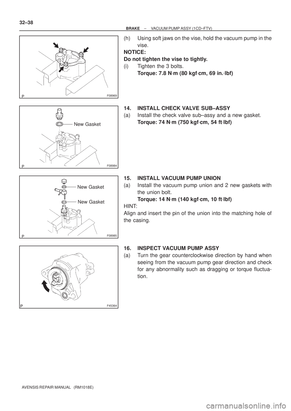
(h) Using soft jaws on the vise, hold the vacuum pump in the
vise.
NOTICE:
Do not tighten the vise to tightly.
(i) Tighten the 3 bolts.
Torque: 7.8 N�m (80 kgf�cm, 69 in.�lbf)
14. INSTALL CHECK VALVE SUB±ASSY
(a) Install the check valve sub±assy and a new gasket.
Torque: 74 N�m (750 kgf�cm, 54 ft�lbf)
15. INSTALL VACUUM PUMP UNION
(a) Install the vacuum pump union and 2 new gaskets with
the union bolt.
Torque: 14 N�m (140 kgf�cm, 10 ft�lbf)
HINT:
Align and insert the pin of the union into the matching hole of
the casing.
16. INSPECT VACUUM PUMP ASSY
(a) Turn the gear counterclockwise direction by hand when
seeing from the vacuum pump gear direction and check
for any abnormality such as dragging or torque fluctua-
tion.
Page 2645 of 5135
������������D30338
U241E:
U341E:
C99454
D31059
D30919N 40±4
± AUTOMATIC TRANSMISSION / TRANSPARK/NEUTRAL POSITION SWITCH ASSY (ATM)
AVENSIS REPAIR MANUAL (RM1018E)
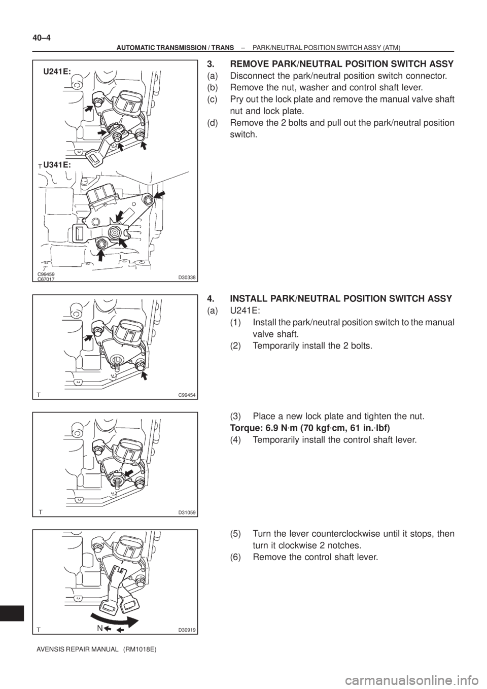
3. REMOVE PARK/NEUTRAL POSITION SWITCH ASSY
(a) Disconnect the park/neutral position switch connector.
(b) Remove the nut, washer and control shaft lever.
(c) Pry out the lock plate and remove the manual valve shaft
nut and lock plate.
(d) Remove the 2 bolts and pull out the park/neutral position
switch.
4. INSTALL PARK/NEUTRAL POSITION SWITCH ASSY
(a) U241E:
(1) Install the park/neutral position switch to the manual
valve shaft.
(2) Temporarily install the 2 bolts.
(3) Place a new lock plate and tighten the nut.
Torque: 6.9 N�m (70 kgf�cm, 61 in.�lbf)
(4) Temporarily install the control shaft lever.
(5) Turn the lever counterclockwise until it stops, then
turn it clockwise 2 notches.
(6) Remove the control shaft lever.
Page 2647 of 5135
C82031
N
������G25654
Groove
Neutral
Basic Line
C62669
C82032
C81535
40±6
± AUTOMATIC TRANSMISSION / TRANSPARK/NEUTRAL POSITION SWITCH ASSY (ATM)
AVENSIS REPAIR MANUAL (RM1018E)
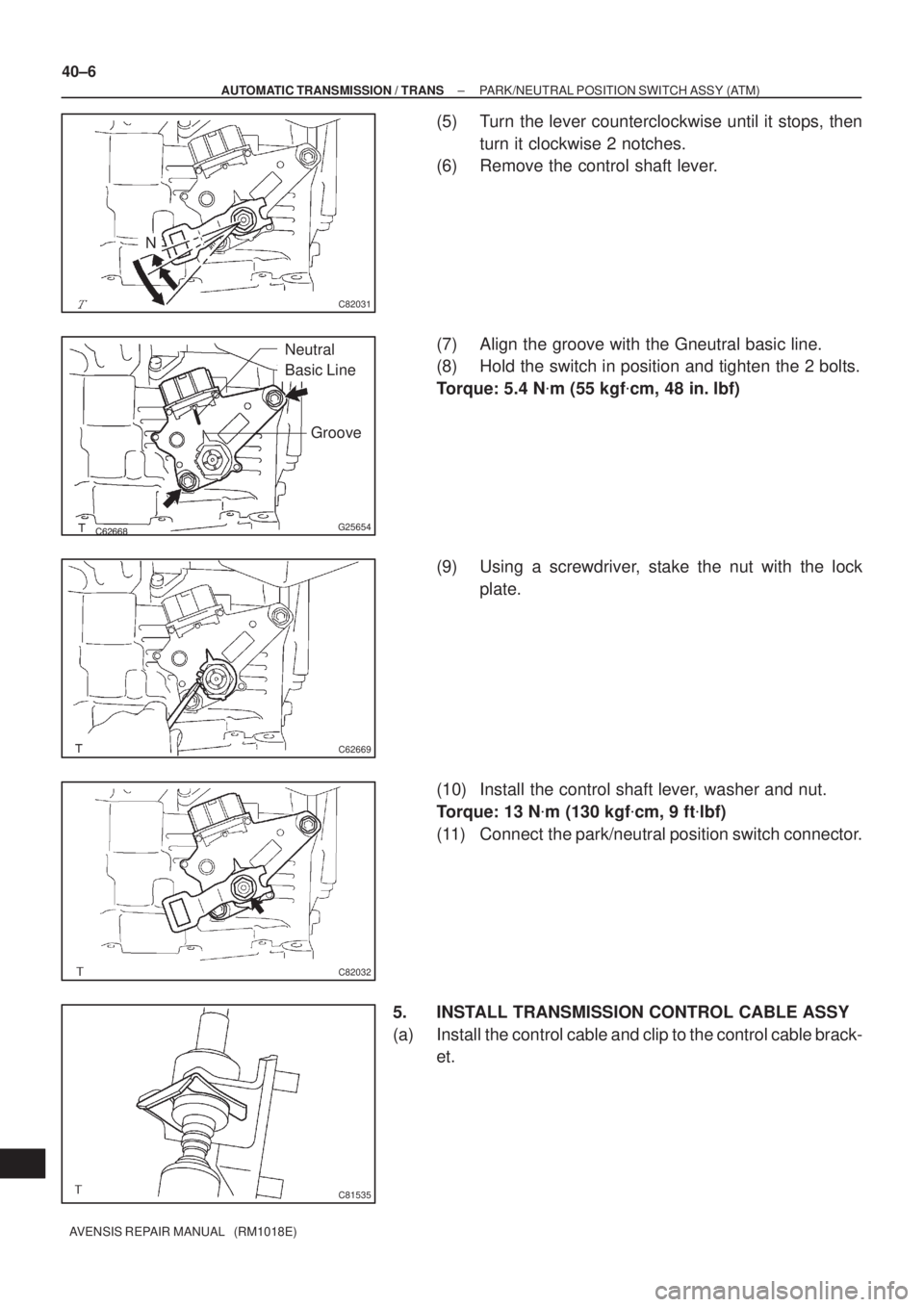
(5) Turn the lever counterclockwise until it stops, then
turn it clockwise 2 notches.
(6) Remove the control shaft lever.
(7) Align the groove with the Gneutral basic line.
(8) Hold the switch in position and tighten the 2 bolts.
Torque: 5.4 N�m (55 kgf�cm, 48 in. lbf)
(9) Using a screwdriver, stake the nut with the lock
plate.
(10) Install the control shaft lever, washer and nut.
Torque: 13 N�m (130 kgf�cm, 9 ft�lbf)
(11) Connect the park/neutral position switch connector.
5. INSTALL TRANSMISSION CONTROL CABLE ASSY
(a) Install the control cable and clip to the control cable brack-
et.
Page 2668 of 5135
3300F±07
F44808
Lock NutAdjusting Nut
33±2
±
PARKING BRAKE PARKING BRAKE SYSTEM
AVENSIS REPAIR MANUAL (RM1018E)
ADJUSTMENT
1. REMOVE REAR WHEEL
2.ADJUST PARKING BRAKE SHOE CLEARANCE (See page 33±14)
3. INSTALL REAR WHEEL Torque: 103 N �m (1,050 kgf �cm, 76 ft �lbf)
4. INSPECT PARKING BRAKE LEVER TRAVEL
(a) Pull the parking brake lever all the way up, and count the number of cli\
cks. Parking brake lever travel: 6 ± 9 clicks at 196 N (20 kgf, 44.1 lbf)\
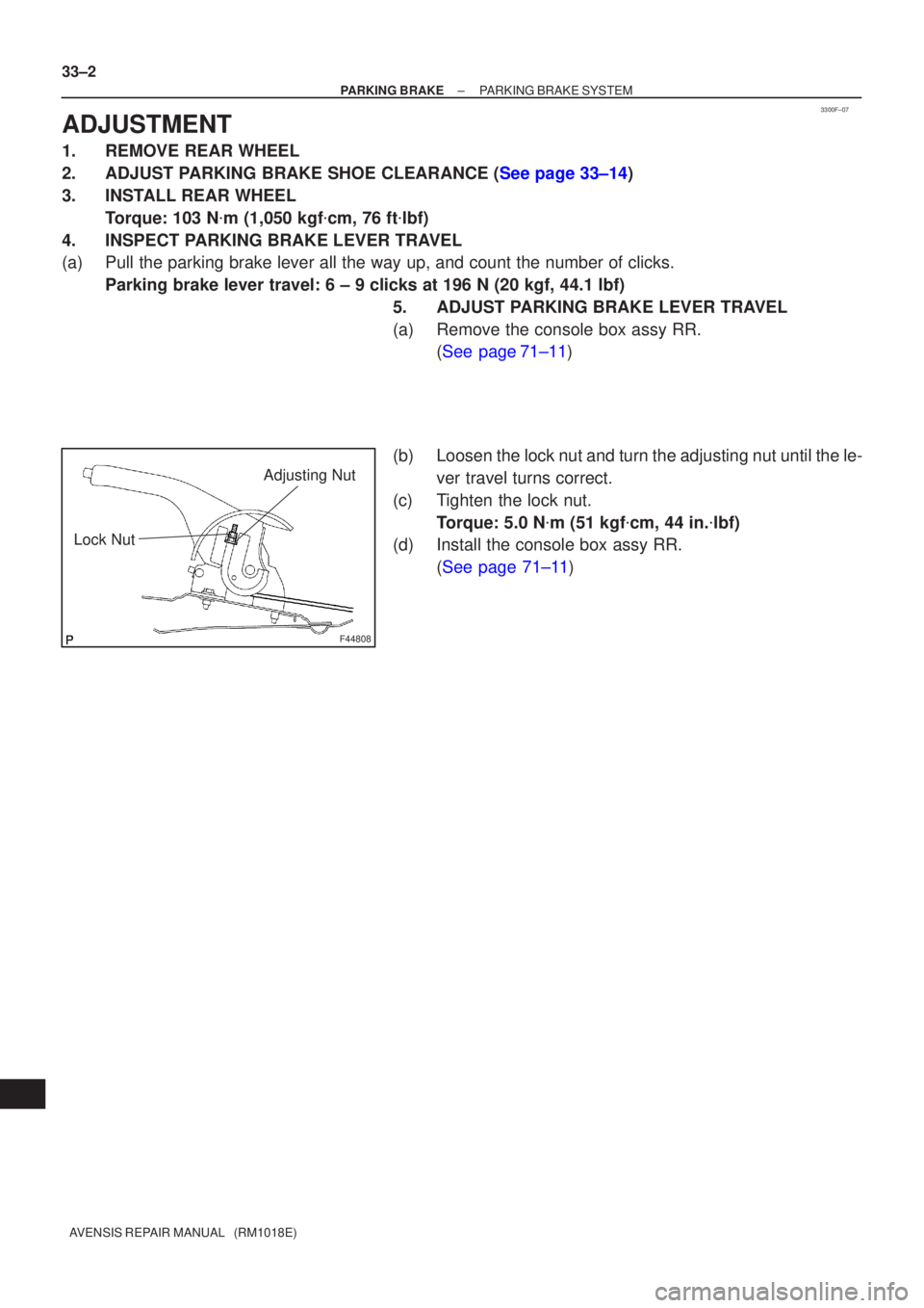
5. ADJUST PARKING BRAKE LEVER TRAVEL
(a) Remove the console box assy RR.(See page71±11)
(b) Loosen the lock nut and turn the adjusting nut until the le- ver travel turns correct.
(c) Tighten the lock nut. Torque: 5.0 N �m (51 kgf �cm, 44 in. �lbf)
(d) Install the console box assy RR.
(See page 71±11)
Page 2691 of 5135
400DN±02
AT0953
SST
AT3306
Hold
TurnLock
Free
D25367
Sample showing minimum amount of
powders in ATF
Actual Size
± AUTOMATIC TRANSMISSION / TRANSTORQUE CONVERTER CLUTCH AND DRIVE
PLATE (ATM)40±37
AVENSIS REPAIR MANUAL (RM1018E)
TORQUE CONVERTER CLUTCH AND DRIVE PLATE (ATM)
INSPECTION
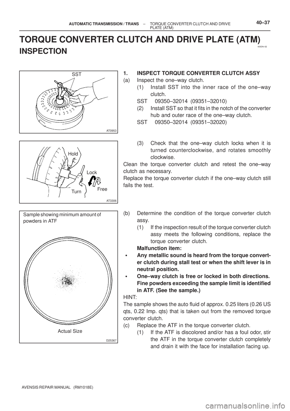
1. INSPECT TORQUE CONVERTER CLUTCH ASSY
(a) Inspect the one±way clutch.
(1) Install SST into the inner race of the one±way
clutch.
SST 09350±32014 (09351±32010)
(2) Install SST so that it fits in the notch of the converter
hub and outer race of the one±way clutch.
SST 09350±32014 (09351±32020)
(3) Check that the one±way clutch locks when it is
turned counterclockwise, and rotates smoothly
clockwise.
Clean the torque converter clutch and retest the one±way
clutch as necessary.
Replace the torque converter clutch if the one±way clutch still
fails the test.
(b) Determine the condition of the torque converter clutch
assy.
(1) If the inspection result of the torque converter clutch
assy meets the following conditions, replace the
torque converter clutch.
Malfunction item:
�Any metallic sound is heard from the torque convert-
er clutch during stall test or when the shift lever is in
neutral position.
�One±way clutch is free or locked in both directions.
Fine powders exceeding the sample limit is identified
in ATF. (See the sample.)
HINT:
The sample shows the auto fluid of approx. 0.25 liters (0.26 US
qts, 0.22 Imp. qts) that is taken out from the removed torque
converter clutch.
(c) Replace the ATF in the torque converter clutch.
(1) If the ATF is discolored and/or has a foul odor, stir
the ATF in the torque converter clutch completely
and drain it with the face for installation facing up.
Page 2814 of 5135
F44800
Marks
F44801
Torx ScrewScrew Case
±
STEERING COLUMN STEERING COLUMN ASSY
50±19
AVENSIS REPAIR MANUAL (RM1018E)
54.INSTALL INSTRUMENT PANEL AIR BAG ASSY (See page 60±54)
55. INSTALL COLUMN HOLE COVER SILENCER SHEET
56. PLACE FRONT WHEELS FACING STRAIGHT AHEAD
57.INSTALL SPIRAL CABLE SUB±ASSY (See page 60±26)
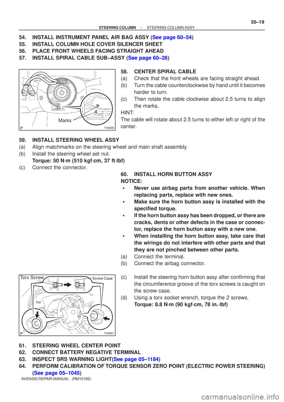
58. CENTER SPIRAL CABLE
(a) Check that the front wheels are facing straight ahead.
(b) Turn the cable counterclockwise by hand until it becomesharder to turn.
(c) Then rotate the cable clockwise about 2.5 turns to align the marks.
HINT:
The cable will rotate about 2.5 turns to either left or right of the
center.
59. INSTALL STEERING WHEEL ASSY
(a) Align matchmarks on the steering wheel and main shaft assembly.
(b) Install the steering wheel set nut. Torque: 50 N´m (510 kgf´cm, 37 ft´lbf)
(c) Connect the connector.
60. INSTALL HORN BUTTON ASSY
NOTICE:
�Never use airbag parts from another vehicle. When
replacing parts, replace with new ones.
�Make sure the horn button assy is installed with the
specified torque.
�If the horn button assy has been dropped, or there are
cracks, dents or other defects in the case or connec-
tor, replace the horn button assy with a new one.
�When installing the horn button assy, take care that
the wirings do not interfere with other parts and that
they are not pinched between other parts.
(a) Connect the terminal.
(b) Connect the airbag connector.
(c) Install the steering horn button assy after confirming that the circumference groove of the torx screws is caught on
the screw case.
(d) Using a torx socket wrench, torque the 2 screws. Torque: 8.8 N´m (90 kgf´cm, 78 in.´lbf)
61. STEERING WHEEL CENTER POINT
62. CONNECT BATTERY NEGATIVE TERMINAL
63.INSPECT SRS WARNING LIGHT(See page 05±1184)
64. PERFORM CALIBRATION OF TORQUE SENSOR ZERO POINT (ELECTRIC POWER STEERING) (See page 05±1045)