Page 2505 of 5135

F45155
������F40197
Inner SideRear
Side
±
FRONT SUSPENSION STABILIZER BAR FRONT
26±27
AVENSIS REPAIR MANUAL (RM1018E)
10. SUSPEND ENGINE ASSY
(a)1ZZ, 3ZZ Engine: See page 41±15
(b)1AZ Engine: See page 41±24
(c)1CD Engine: See page 41±33
11.REMOVE FRONT SUSPENSION MEMBER BRACE REAR LH (See page 26±16)
12. REMOVE FRONT SUSPENSION MEMBER BRACE REAR RH
HINT:
Remove the RH side by the same procedures as the LH side.
13.SEPARATE FRONT SUSPENSION CROSSMEMBER SUB±ASSY (See page 26±16)
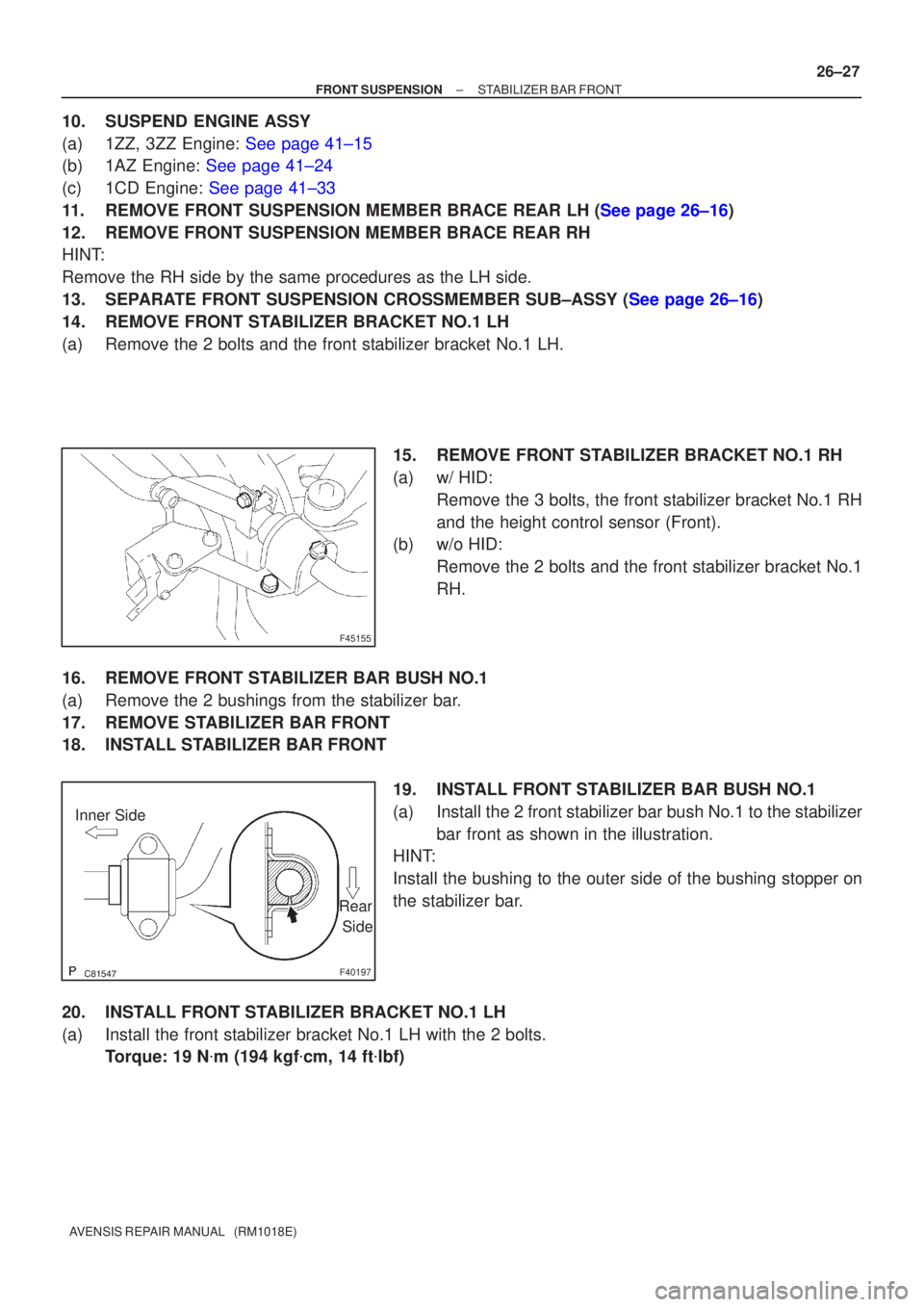
14. REMOVE FRONT STABILIZER BRACKET NO.1 LH
(a) Remove the 2 bolts and the front stabilizer bracket No.1 LH.
15. REMOVE FRONT STABILIZER BRACKET NO.1 RH
(a) w/ HID:Remove the 3 bolts, the front stabilizer bracket No.1 RH
and the height control sensor (Front).
(b) w/o HID:
Remove the 2 bolts and the front stabilizer bracket No.1
RH.
16. REMOVE FRONT STABILIZER BAR BUSH NO.1
(a) Remove the 2 bushings from the stabilizer bar.
17. REMOVE STABILIZER BAR FRONT
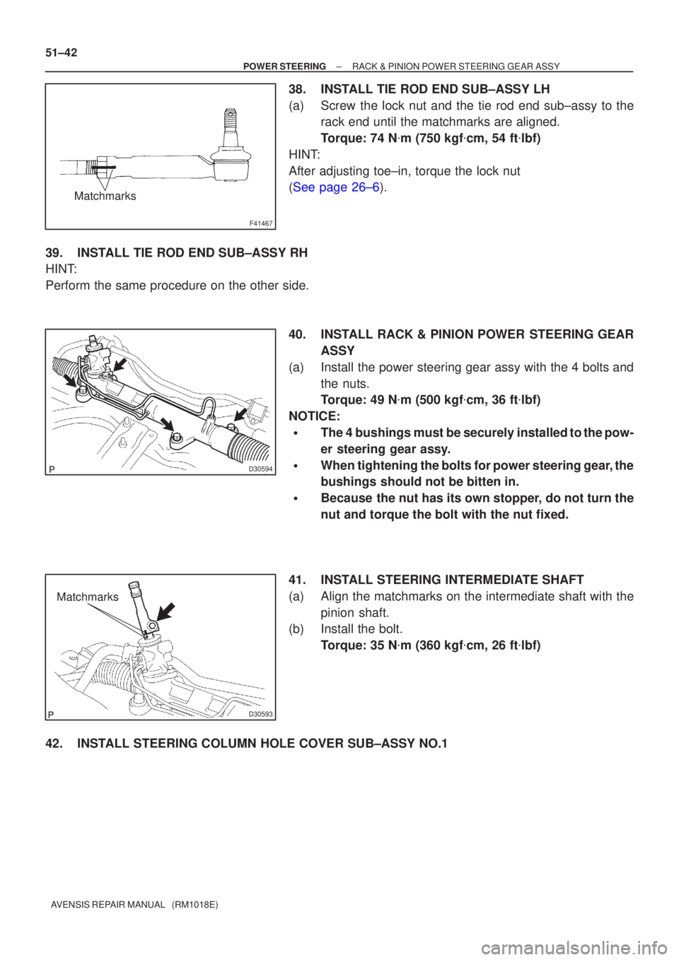
18. INSTALL STABILIZER BAR FRONT 19. INSTALL FRONT STABILIZER BAR BUSH NO.1
(a) Install the 2 front stabilizer bar bush No.1 to the stabilizerbar front as shown in the illustration.
HINT:
Install the bushing to the outer side of the bushing stopper on
the stabilizer bar.
20. INSTALL FRONT STABILIZER BRACKET NO.1 LH
(a) Install the front stabilizer bracket No.1 LH with the 2 bolts. Torque: 19 N �m (194 kgf �cm, 14 ft �lbf)
Page 2848 of 5135

F41467
Matchmarks
D30594
D30593
Matchmarks
51±42
±
POWER STEERING RACK & PINION POWER STEERING GEAR ASSY
AVENSIS REPAIR MANUAL (RM1018E)
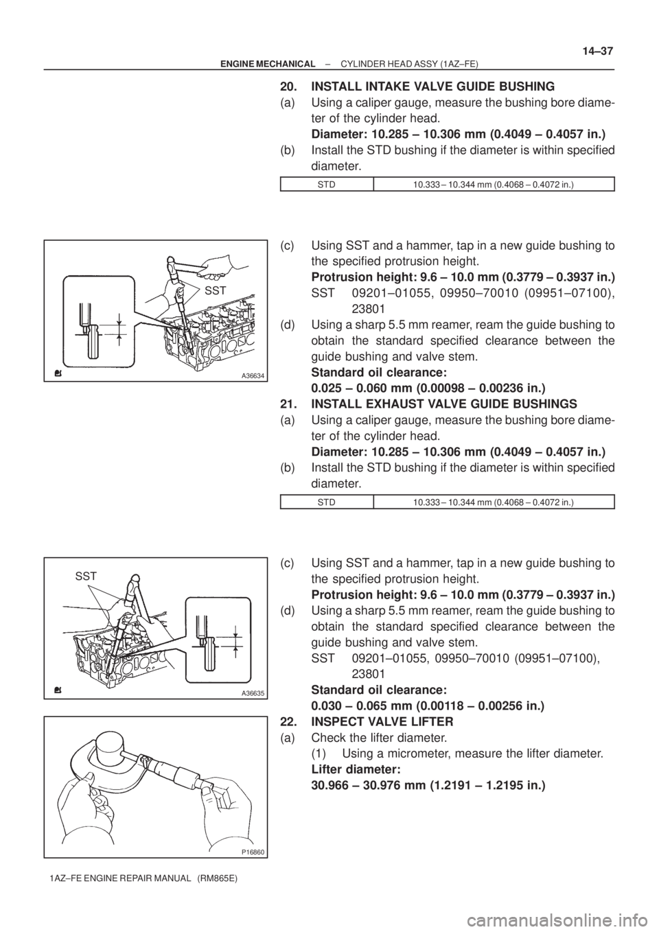
38. INSTALL TIE ROD END SUB±ASSY LH
(a) Screw the lock nut and the tie rod end sub±assy to the rack end until the matchmarks are aligned.
Torque: 74 N �m (750 kgf �cm, 54 ft �lbf)
HINT:
After adjusting toe±in, torque the lock nut
(See page 26±6).
39. INSTALL TIE ROD END SUB±ASSY RH
HINT:
Perform the same procedure on the other side. 40. INSTALL RACK & PINION POWER STEERING GEARASSY
(a) Install the power steering gear assy with the 4 bolts and the nuts.
Torque: 49 N �m (500 kgf �cm, 36 ft �lbf)
NOTICE:
�The 4 bushings must be securely installed to the pow-
er steering gear assy.
�When tightening the bolts for power steering gear, the
bushings should not be bitten in.
�Because the nut has its own stopper, do not turn the
nut and torque the bolt with the nut fixed.
41. INSTALL STEERING INTERMEDIATE SHAFT
(a) Align the matchmarks on the intermediate shaft with the pinion shaft.
(b) Install the bolt.
Torque: 35 N �m (360 kgf �cm, 26 ft �lbf)
42. INSTALL STEERING COLUMN HOLE COVER SUB±ASSY NO.1
Page 3733 of 5135
A13367
A13837
SST
A36632
A13837
SST
A36633
14±36
± ENGINE MECHANICALCYLINDER HEAD ASSY (1AZ±FE)
1AZ±FE ENGINE REPAIR MANUAL (RM865E)
17. INSPECT EXHAUST VALVE GUIDE BUSHINGS
(a) Using a caliper gauge, measure the inside diameter of the
guide bushing.
Bushing inside diameter:
5.510 ± 5.530 mm (0.2169 ± 0.2177 in.)
(b) Subtract the valve stem diameter measurement from the
guide bushing inside diameter measurement.
Standard oil clearance:
0.030 ± 0.065 mm (0.0012 ± 0.0026 in.)
Maximum oil clearance: 0.10 mm (0.0039 in.)
18. REMOVE INTAKE VALVE GUIDE BUSHING
(a) Gradually heat the cylinder head to 80 ± 100�C (176 ±
212�F).
(b) Using SST and a hammer, tap out the guide bushing.
SST 09201±01055, 09950±70010 (09951±07100)
19. REMOVE EXHAUST VALVE GUIDE BUSHINGS
(a) Gradually heat the cylinder head to 80 ± 100�C (176 ±
212�F).
(b) Using SST and a hammer, tap out the guide bushing.
SST 09201±01055, 09950±70010 (09951±07100)
Page 3734 of 5135

SST
A36634
SST
A36635
P16860
± ENGINE MECHANICALCYLINDER HEAD ASSY (1AZ±FE)
14±37
1AZ±FE ENGINE REPAIR MANUAL (RM865E)
20. INSTALL INTAKE VALVE GUIDE BUSHING
(a) Using a caliper gauge, measure the bushing bore diame-
ter of the cylinder head.
Diameter: 10.285 ± 10.306 mm (0.4049 ± 0.4057 in.)
(b) Install the STD bushing if the diameter is within specified
diameter.
STD10.333 ± 10.344 mm (0.4068 ± 0.4072 in.)
(c) Using SST and a hammer, tap in a new guide bushing to
the specified protrusion height.
Protrusion height: 9.6 ± 10.0 mm (0.3779 ± 0.3937 in.)
SST 09201±01055, 09950±70010 (09951±07100),
23801
(d) Using a sharp 5.5 mm reamer, ream the guide bushing to
obtain the standard specified clearance between the
guide bushing and valve stem.
Standard oil clearance:
0.025 ± 0.060 mm (0.00098 ± 0.00236 in.)
21. INSTALL EXHAUST VALVE GUIDE BUSHINGS
(a) Using a caliper gauge, measure the bushing bore diame-
ter of the cylinder head.
Diameter: 10.285 ± 10.306 mm (0.4049 ± 0.4057 in.)
(b) Install the STD bushing if the diameter is within specified
diameter.
STD10.333 ± 10.344 mm (0.4068 ± 0.4072 in.)
(c) Using SST and a hammer, tap in a new guide bushing to
the specified protrusion height.
Protrusion height: 9.6 ± 10.0 mm (0.3779 ± 0.3937 in.)
(d) Using a sharp 5.5 mm reamer, ream the guide bushing to
obtain the standard specified clearance between the
guide bushing and valve stem.
SST 09201±01055, 09950±70010 (09951±07100),
23801
Standard oil clearance:
0.030 ± 0.065 mm (0.00118 ± 0.00256 in.)
22. INSPECT VALVE LIFTER
(a) Check the lifter diameter.
(1) Using a micrometer, measure the lifter diameter.
Lifter diameter:
30.966 ± 30.976 mm (1.2191 ± 1.2195 in.)