Page 1982 of 5135
A62180
Disconnect
Hook
Pin Turn
A62181
Plunger
Turn
Push
A11858
A64005
14±16
± ENGINE MECHANICALVALVE CLEARANCE (1ZZ±FE/3ZZ±FE)
AVENSIS REPAIR MANUAL (RM1018E)
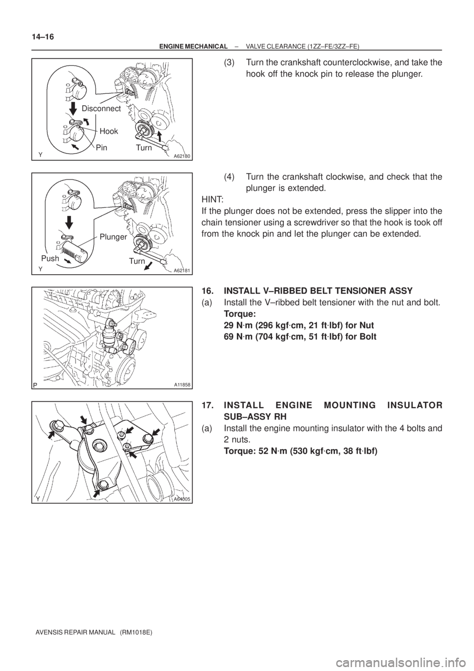
(3) Turn the crankshaft counterclockwise, and take the
hook off the knock pin to release the plunger.
(4) Turn the crankshaft clockwise, and check that the
plunger is extended.
HINT:
If the plunger does not be extended, press the slipper into the
chain tensioner using a screwdriver so that the hook is took off
from the knock pin and let the plunger can be extended.
16. INSTALL V±RIBBED BELT TENSIONER ASSY
(a) Install the V±ribbed belt tensioner with the nut and bolt.
Torque:
29 N�m (296 kgf�cm, 21 ft�lbf) for Nut
69 N�m (704 kgf�cm, 51 ft�lbf) for Bolt
17. INSTALL ENGINE MOUNTING INSULATOR
SUB±ASSY RH
(a) Install the engine mounting insulator with the 4 bolts and
2 nuts.
Torque: 52 N�m (530 kgf�cm, 38 ft�lbf)
Page 2021 of 5135
A62178
Push
A62180
DisconnectHook
PinTurn
A62181
Plunger
Turn
Push
A11858
A64005
±
ENGINE MECHANICAL CAMSHAFT(1ZZ±FE/3ZZ±FE)
14±73
AVENSIS REPAIR MANUAL (RM1018E)
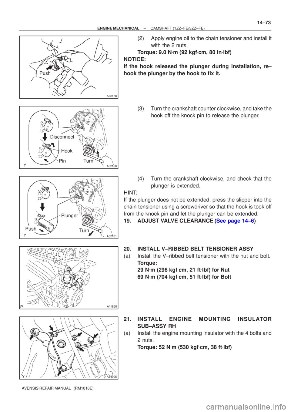
(2)Apply engine oil to the chain tensioner and install it
with the 2 nuts.
Torque: 9.0 N �m (92 kgf �cm, 80 in �lbf)
NOTICE:
If the hook released the plunger during installation, re±
hook the plunger by the hook to fix it.
(3)Turn the crankshaft counter clockwise, and take thehook off the knock pin to release the plunger.
(4)Turn the crankshaft clockwise, and check that the plunger is extended.
HINT:
If the plunger does not be extended, press the slipper into the
chain tensioner using a screwdriver so that the hook is took off
from the knock pin and let the plunger can be extended.
19.ADJUST VALVE CLEARANCE(See page 14±6)
20. INSTALL V±RIBBED BELT TENSIONER ASSY
(a) Install the V±ribbed belt tensioner with the nut and bolt. Torque:
29 N�m (296 kgf �cm, 21 ft �lbf) for Nut
69 N �m (704 kgf �cm, 51 ft �lbf) for Bolt
21. INSTALL ENGINE MOUNTING INSULATOR SUB±ASSY RH
(a) Install the engine mounting insulator with the 4 bolts and
2 nuts.
Torque: 52 N �m (530 kgf �cm, 38 ft �lbf)
Page 2032 of 5135
A30857
A10079
A62170
Set KeyUpward
A62171
Yellow
Color Link
Timing Mark
A62172
SST
± ENGINE MECHANICALCHAIN SUB±ASSY (1ZZ±FE/3ZZ±FE)
14±53
AVENSIS REPAIR MANUAL (RM1018E)
27. REMOVE CHAIN SUB±ASSY
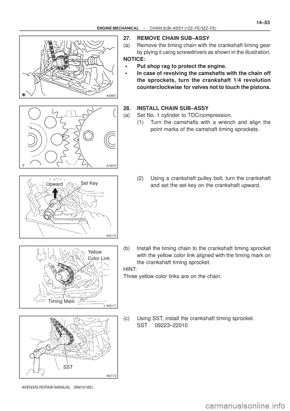
(a) Remove the timing chain with the crankshaft timing gear
by plying it using screwdrivers as shown in the illustration.
NOTICE:
�Put shop rag to protect the engine.
�In case of revolving the camshafts with the chain off
the sprockets, turn the crankshaft 1/4 revolution
counterclockwise for valves not to touch the pistons.
28. INSTALL CHAIN SUB±ASSY
(a) Set No. 1 cylinder to TDC/compression.
(1) Turn the camshafts with a wrench and align the
point marks of the camshaft timing sprockets.
(2) Using a crankshaft pulley bolt, turn the crankshaft
and set the set key on the crankshaft upward.
(b) Install the timing chain to the crankshaft timing sprocket
with the yellow color link aligned with the timing mark on
the crankshaft timing sprocket.
HINT:
Three yellow color links are on the chain.
(c) Using SST, install the crankshaft timing sprocket.
SST 09223±22010
Page 2036 of 5135
A62837SST
A62180
Disconnect
Hook
Pin Turn
A62181
Plunger
Turn
Push
A62182
Seal Packing
± ENGINE MECHANICALCHAIN SUB±ASSY (1ZZ±FE/3ZZ±FE)
14±57
AVENSIS REPAIR MANUAL (RM1018E)
38. INSTALL CRANKSHAFT PULLEY
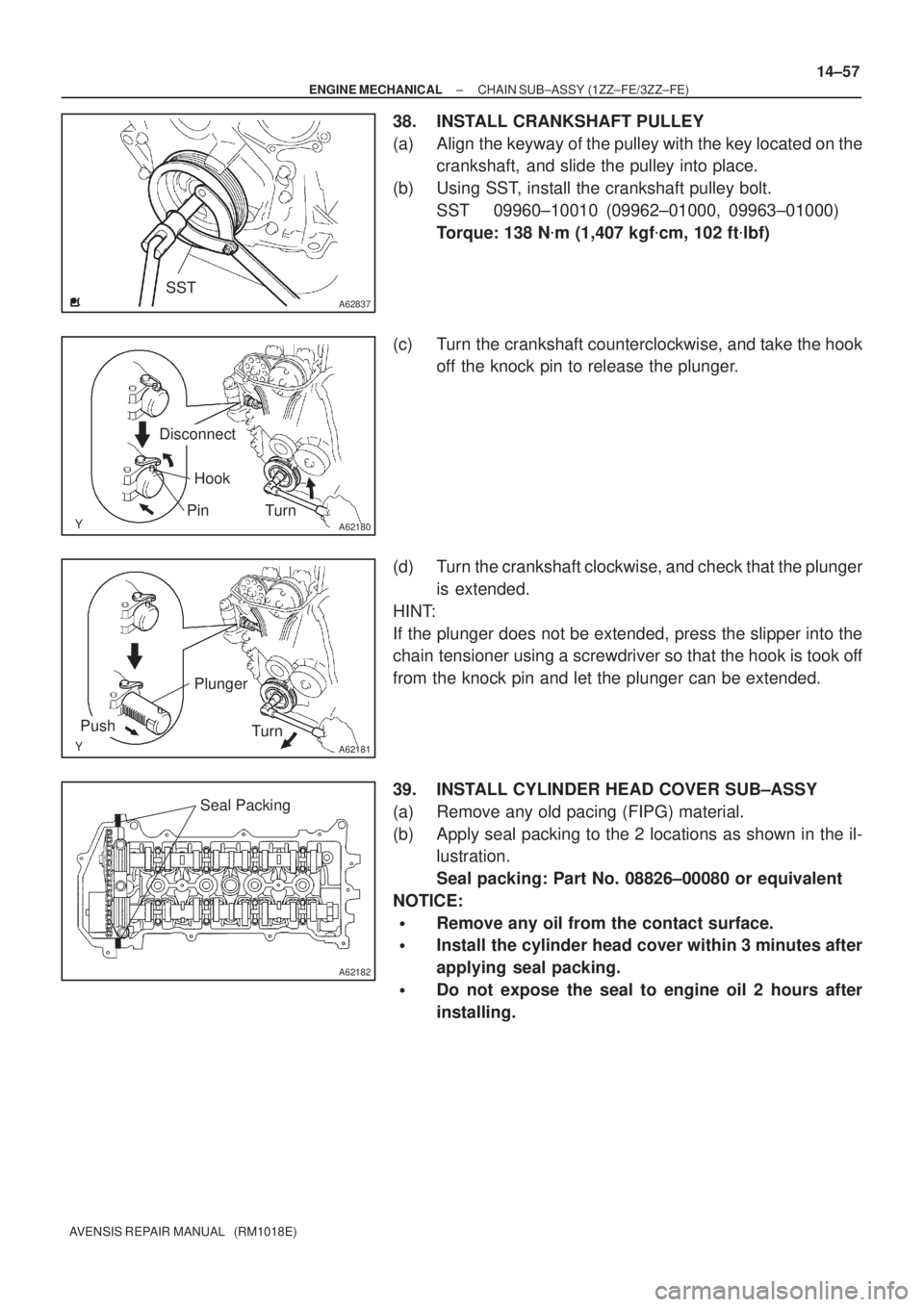
(a) Align the keyway of the pulley with the key located on the
crankshaft, and slide the pulley into place.
(b) Using SST, install the crankshaft pulley bolt.
SST 09960±10010 (09962±01000, 09963±01000)
Torque: 138 N�m (1,407 kgf�cm, 102 ft�lbf)
(c) Turn the crankshaft counterclockwise, and take the hook
off the knock pin to release the plunger.
(d) Turn the crankshaft clockwise, and check that the plunger
is extended.
HINT:
If the plunger does not be extended, press the slipper into the
chain tensioner using a screwdriver so that the hook is took off
from the knock pin and let the plunger can be extended.
39. INSTALL CYLINDER HEAD COVER SUB±ASSY
(a) Remove any old pacing (FIPG) material.
(b) Apply seal packing to the 2 locations as shown in the il-
lustration.
Seal packing: Part No. 08826±00080 or equivalent
NOTICE:
�Remove any oil from the contact surface.
�Install the cylinder head cover within 3 minutes after
applying seal packing.
�Do not expose the seal to engine oil 2 hours after
installing.
Page 2114 of 5135
A30857
A62814
4 2531
A62816
2
5 3
110 8 4 796
A62827
Lot No.
A62820
Overall Length
± ENGINE MECHANICALCYLINDER HEAD GASKET (1ZZ±FE/3ZZ±FE)
14±87
AVENSIS REPAIR MANUAL (RM1018E)
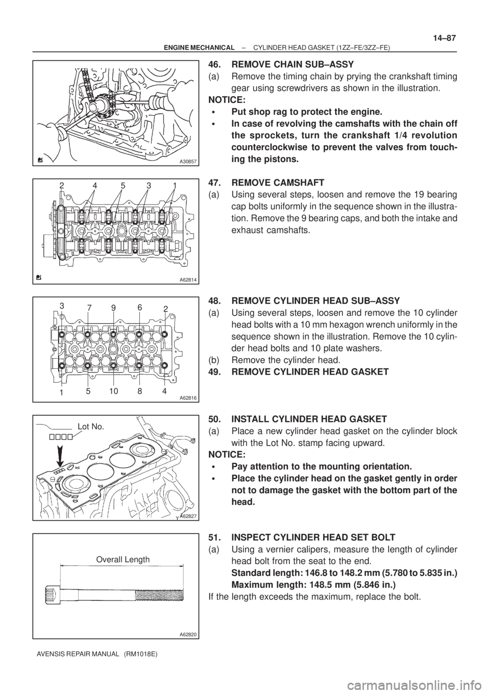
46. REMOVE CHAIN SUB±ASSY
(a) Remove the timing chain by prying the crankshaft timing
gear using screwdrivers as shown in the illustration.
NOTICE:
�Put shop rag to protect the engine.
�In case of revolving the camshafts with the chain off
the sprockets, turn the crankshaft 1/4 revolution
counterclockwise to prevent the valves from touch-
ing the pistons.
47. REMOVE CAMSHAFT
(a) Using several steps, loosen and remove the 19 bearing
cap bolts uniformly in the sequence shown in the illustra-
tion. Remove the 9 bearing caps, and both the intake and
exhaust camshafts.
48. REMOVE CYLINDER HEAD SUB±ASSY
(a) Using several steps, loosen and remove the 10 cylinder
head bolts with a 10 mm hexagon wrench uniformly in the
sequence shown in the illustration. Remove the 10 cylin-
der head bolts and 10 plate washers.
(b) Remove the cylinder head.
49. REMOVE CYLINDER HEAD GASKET
50. INSTALL CYLINDER HEAD GASKET
(a) Place a new cylinder head gasket on the cylinder block
with the Lot No. stamp facing upward.
NOTICE:
�Pay attention to the mounting orientation.
�Place the cylinder head on the gasket gently in order
not to damage the gasket with the bottom part of the
head.
51. INSPECT CYLINDER HEAD SET BOLT
(a) Using a vernier calipers, measure the length of cylinder
head bolt from the seat to the end.
Standard length: 146.8 to 148.2 mm (5.780 to 5.835 in.)
Maximum length: 148.5 mm (5.846 in.)
If the length exceeds the maximum, replace the bolt.
Page 2119 of 5135
A12816
A11858
A62837SST
A62180
DisconnectHook
PinTurn
A62181
Plunger
Turn
Push
14±92
±
ENGINE MECHANICAL CYLINDER HEAD GASKET(1ZZ±FE/3ZZ±FE)
AVENSIS REPAIR MANUAL (RM1018E)
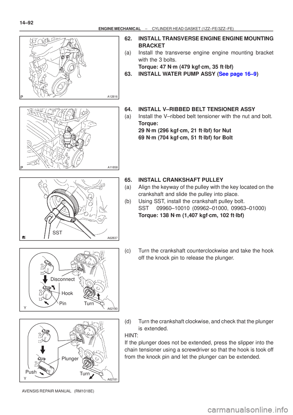
62.INSTALL TRANSVERSE ENGINE ENGINE MOUNTING BRACKET
(a)Install the transverse engine engine mounting bracket
with the 3 bolts.
Torque: 47 N �m (479 kgf �cm, 35 ft �lbf)
63.INSTALL WATER PUMP ASSY (See page 16±9)
64. INSTALL V±RIBBED BELT TENSIONER ASSY
(a) Install the V±ribbed belt tensioner with the nut and bolt. Torque:
29 N�m (296 kgf �cm, 21 ft �lbf) for Nut
69 N �m (704 kgf �cm, 51 ft �lbf) for Bolt
65. INSTALL CRANKSHAFT PULLEY
(a) Align the keyway of the pulley with the key located on the crankshaft and slide the pulley into place.
(b) Using SST, install the crankshaft pulley bolt. SST 09960±10010 (09962±01000, 09963±01000)
Torque: 138 N �m (1,407 kgf �cm, 102 ft �lbf)
(c) Turn the crankshaft counterclockwise and take the hook off the knock pin to release the plunger.
(d) Turn the crankshaft clockwise, and check that the plunger is extended.
HINT:
If the plunger does not be extended, press the slipper into the
chain tensioner using a screwdriver so that the hook is took off
from the knock pin and let the plunger can be extended.
Page 2138 of 5135
A31032
A32639
A77414
Straight
Pin
Key
Groove 14±174
± ENGINE MECHANICALCAMSHAFT (1AZ±FE)
AVENSIS REPAIR MANUAL (RM1018E)
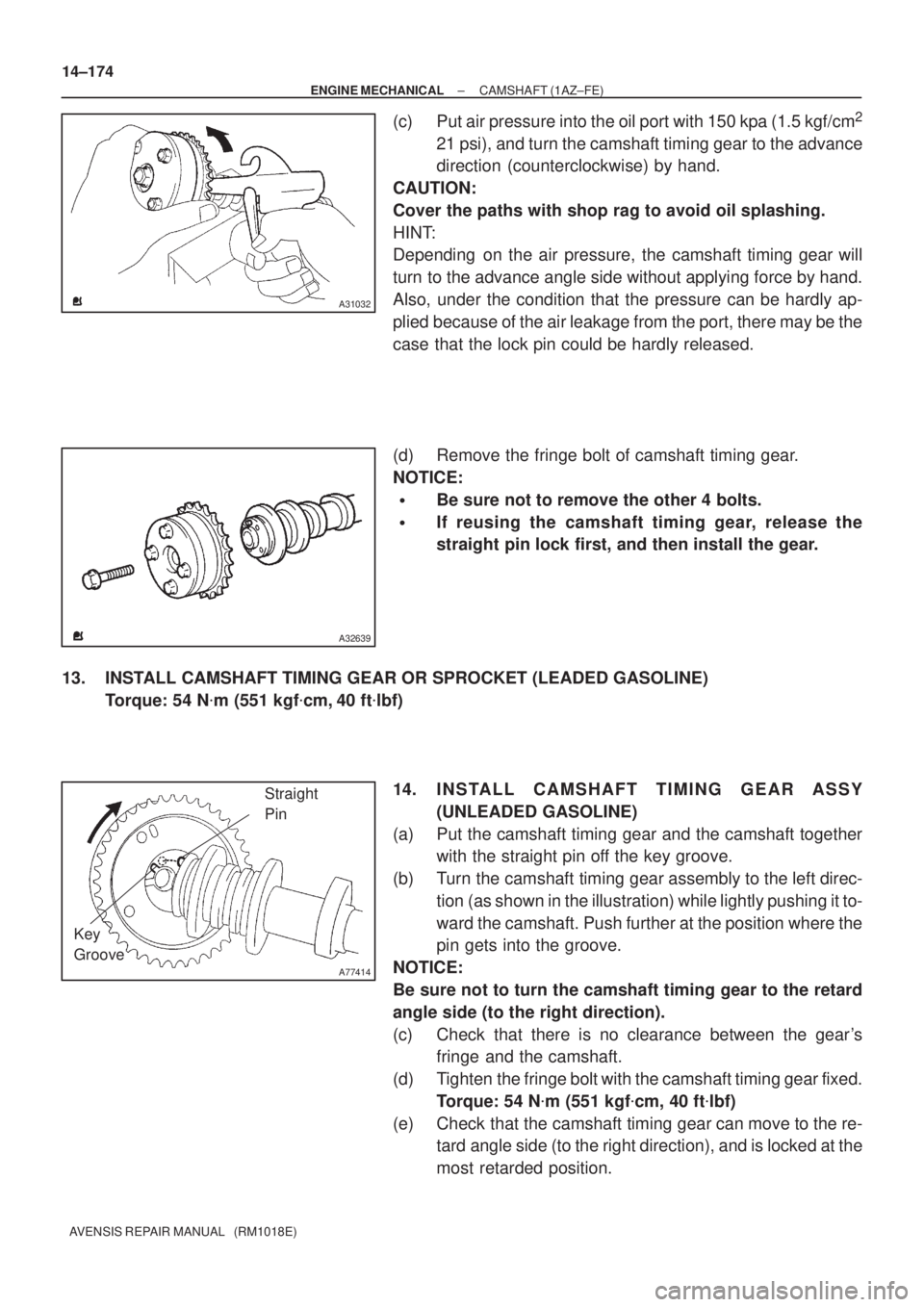
(c) Put air pressure into the oil port with 150 kpa (1.5 kgf/cm2
21 psi), and turn the camshaft timing gear to the advance
direction (counterclockwise) by hand.
CAUTION:
Cover the paths with shop rag to avoid oil splashing.
HINT:
Depending on the air pressure, the camshaft timing gear will
turn to the advance angle side without applying force by hand.
Also, under the condition that the pressure can be hardly ap-
plied because of the air leakage from the port, there may be the
case that the lock pin could be hardly released.
(d) Remove the fringe bolt of camshaft timing gear.
NOTICE:
�Be sure not to remove the other 4 bolts.
�If reusing the camshaft timing gear, release the
straight pin lock first, and then install the gear.
13. INSTALL CAMSHAFT TIMING GEAR OR SPROCKET (LEADED GASOLINE)
Torque: 54 N�m (551 kgf�cm, 40 ft�lbf)
14. INSTALL CAMSHAFT TIMING GEAR ASSY
(UNLEADED GASOLINE)
(a) Put the camshaft timing gear and the camshaft together
with the straight pin off the key groove.
(b) Turn the camshaft timing gear assembly to the left direc-
tion (as shown in the illustration) while lightly pushing it to-
ward the camshaft. Push further at the position where the
pin gets into the groove.
NOTICE:
Be sure not to turn the camshaft timing gear to the retard
angle side (to the right direction).
(c) Check that there is no clearance between the gear's
fringe and the camshaft.
(d) Tighten the fringe bolt with the camshaft timing gear fixed.
Torque: 54 N�m (551 kgf�cm, 40 ft�lbf)
(e) Check that the camshaft timing gear can move to the re-
tard angle side (to the right direction), and is locked at the
most retarded position.
Page 2141 of 5135
A77396
HookPin
Turn
Disconnect
A77397
Push
Turn
Plunger
A77399
Seal Packing
A77400NutNut
A
BC A
AAAB
± ENGINE MECHANICALCAMSHAFT (1AZ±FE)
14±177
AVENSIS REPAIR MANUAL (RM1018E)
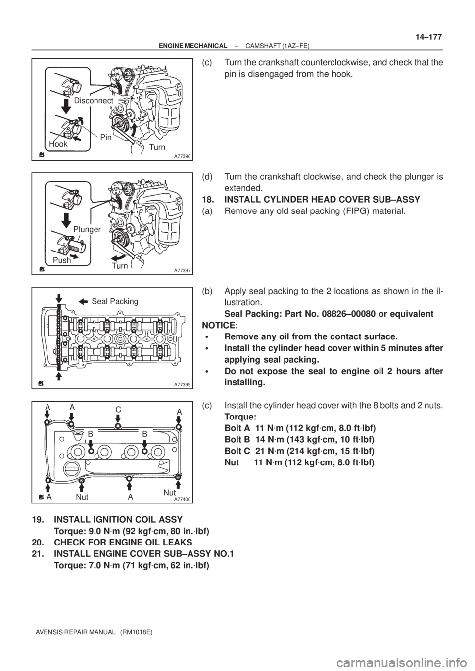
(c) Turn the crankshaft counterclockwise, and check that the
pin is disengaged from the hook.
(d) Turn the crankshaft clockwise, and check the plunger is
extended.
18. INSTALL CYLINDER HEAD COVER SUB±ASSY
(a) Remove any old seal packing (FIPG) material.
(b) Apply seal packing to the 2 locations as shown in the il-
lustration.
Seal Packing: Part No. 08826±00080 or equivalent
NOTICE:
�Remove any oil from the contact surface.
�Install the cylinder head cover within 5 minutes after
applying seal packing.
�Do not expose the seal to engine oil 2 hours after
installing.
(c) Install the cylinder head cover with the 8 bolts and 2 nuts.
Torque:
Bolt A 11 N�m (112 kgf�cm, 8.0 ft�lbf)
Bolt B 14 N�m (143 kgf�cm, 10 ft�lbf)
Bolt C 21 N�m (214 kgf�cm, 15 ft�lbf)
Nut 11 N�m (112 kgf�cm, 8.0 ft�lbf)
19. INSTALL IGNITION COIL ASSY
Torque: 9.0 N�m (92 kgf�cm, 80 in.�lbf)
20. CHECK FOR ENGINE OIL LEAKS
21. INSTALL ENGINE COVER SUB±ASSY NO.1
Torque: 7.0 N�m (71 kgf�cm, 62 in.�lbf)