D30479
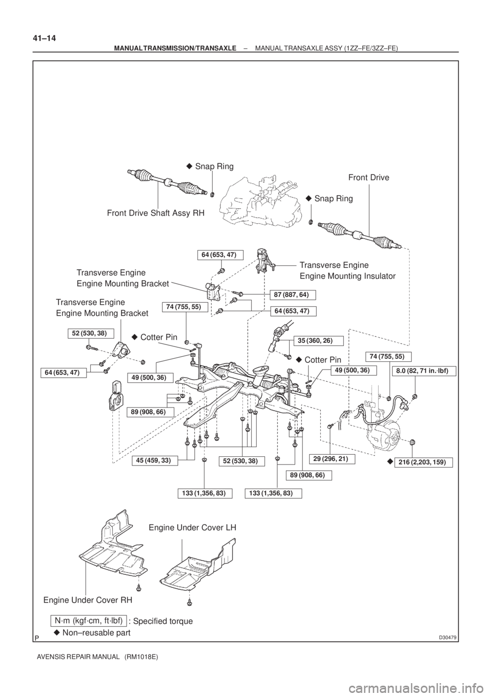
Front Drive Shaft Assy RH� Snap Ring
Front Drive
� Snap Ring
Transverse Engine
Engine Mounting BracketTransverse Engine
Engine Mounting Insulator
64 (653, 47)
87 (887, 64)Transverse Engine
Engine Mounting Bracket
� Cotter Pin
64 (653, 47)
52 (530, 38)
� Cotter Pin
Engine Under Cover RH
� Non±reusable part
N´m (kgf´cm, ft´lbf)
: Specified torque
64 (653, 47)
�216 (2,203, 159)45 (459, 33)
Engine Under Cover LH
35 (360, 26)
74 (755, 55)
52 (530, 38)
49 (500, 36)
133 (1,356, 83)
29 (296, 21)
49 (500, 36)
74 (755, 55)
89 (908, 66)
8.0 (82, 71 in.�lbf)
133 (1,356, 83)
89 (908, 66)
41±14
± MANUAL TRANSMISSION/TRANSAXLEMANUAL TRANSAXLE ASSY (1ZZ±FE/3ZZ±FE)
AVENSIS REPAIR MANUAL (RM1018E)
C80366
C80367
C80368
C80369
C80586
41±14
± MANUAL TRANSMISSION/TRANSAXLEMANUAL TRANSAXLE ASSY (C250)
C250 M/T REPAIR MANUAL (RM1020E)
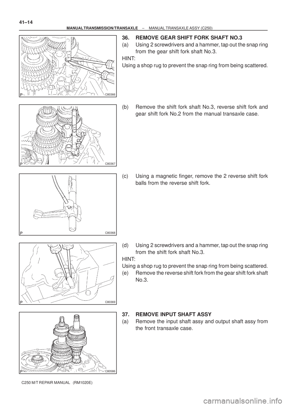
36. REMOVE GEAR SHIFT FORK SHAFT NO.3
(a) Using 2 screwdrivers and a hammer, tap out the snap ring
from the gear shift fork shaft No.3.
HINT:
Using a shop rug to prevent the snap ring from being scattered.
(b) Remove the shift fork shaft No.3, reverse shift fork and
gear shift fork No.2 from the manual transaxle case.
(c) Using a magnetic finger, remove the 2 reverse shift fork
balls from the reverse shift fork.
(d) Using 2 screwdrivers and a hammer, tap out the snap ring
from the shift fork shaft No.3.
HINT:
Using a shop rug to prevent the snap ring from being scattered.
(e) Remove the reverse shift fork from the gear shift fork shaft
No.3.
37. REMOVE INPUT SHAFT ASSY
(a) Remove the input shaft assy and output shaft assy from
the front transaxle case.