Page 2177 of 5135
A77321
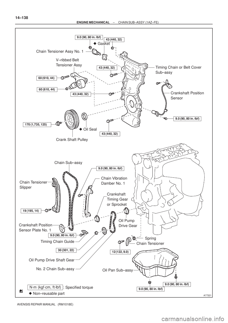
N´m (kgf´cm, ft´lbf)
: Specified torque
� Non±reusable part
43 (440, 32)
� Gasket
Chain Tensioner Assy No. 1
Timing Chain or Belt Cover
Sub±assy
Crankshaft Position
Sensor
9.0 (90, 80 in.�lbf)
V±ribbed Belt
Tensioner Assy
60 (610, 44)
60 (610, 44)
43 (440, 32)
43 (440, 32)
170 (1,735, 125)
Crank Shaft Pulley
� Oil Seal
43 (440, 32)
Chain Sub±assy
Chain Tensioner
Slipper
Chain Vibration
Damber No. 1
Crankshaft
Timing Gear
or Sprocket
19 (195, 14)
Crankshaft Position
Sensor Plate No. 1
Timing Chain Guide
Oil Pump
Drive Gear
12 (122, 9.0)
Spring
Chain Tensioner
Oil Pump Drive Shaft Gear
Oil Pan Sub±assy
9.0 (90, 80 in.�lbf)
9.0 (90, 80 in.�lbf)
9.0 (90, 80 in.�lbf)
30 (301, 22)
No. 2 Chain Sub±assy
9.0 (90, 80 in.�lbf)
9.0 (90, 80 in.�lbf)
14±138
± ENGINE MECHANICALCHAIN SUB±ASSY (1AZ±FE)
AVENSIS REPAIR MANUAL (RM1018E)
Page 2186 of 5135
A77289
Pry
A77243
± ENGINE MECHANICALCHAIN SUB±ASSY (1AZ±FSE)
14±227
AVENSIS REPAIR MANUAL (RM1018E)
34. REMOVE TIMING CHAIN OR BELT COVER
SUB±ASSY
(a) Remove the 14 bolts and 2 nuts.
(b) Using a screwdriver, pry between the timing chain cover
and cylinder head or cylinder block.
(c) Remove the timing chain cover.
NOTICE:
Be careful not to damage the contact surface of the timing
chain cover, cylinder head and cylinder block.
35. REMOVE CRANKSHAFT POSITION SENSOR PLATE NO.1
36. REMOVE CHAIN TENSIONER SLIPPER
(a) Remove the 2 bolts and the chain tensioner slipper.
37. REMOVE CHAIN VIBRATION DAMPER NO.1
(a) Remove the bolt and the chain vibration damper No. 1
38. REMOVE TIMING CHAIN GUIDE
(a) Remove the bolt and the timing chain guide.
39. REMOVE CHAIN SUB±ASSY
40. REMOVE CRANKSHAFT TIMING GEAR OR SPROCKET
Page 2187 of 5135
A77382
Groove90�
A77383
Groove
A66833
B11424
14±228
± ENGINE MECHANICALCHAIN SUB±ASSY (1AZ±FSE)
AVENSIS REPAIR MANUAL (RM1018E)
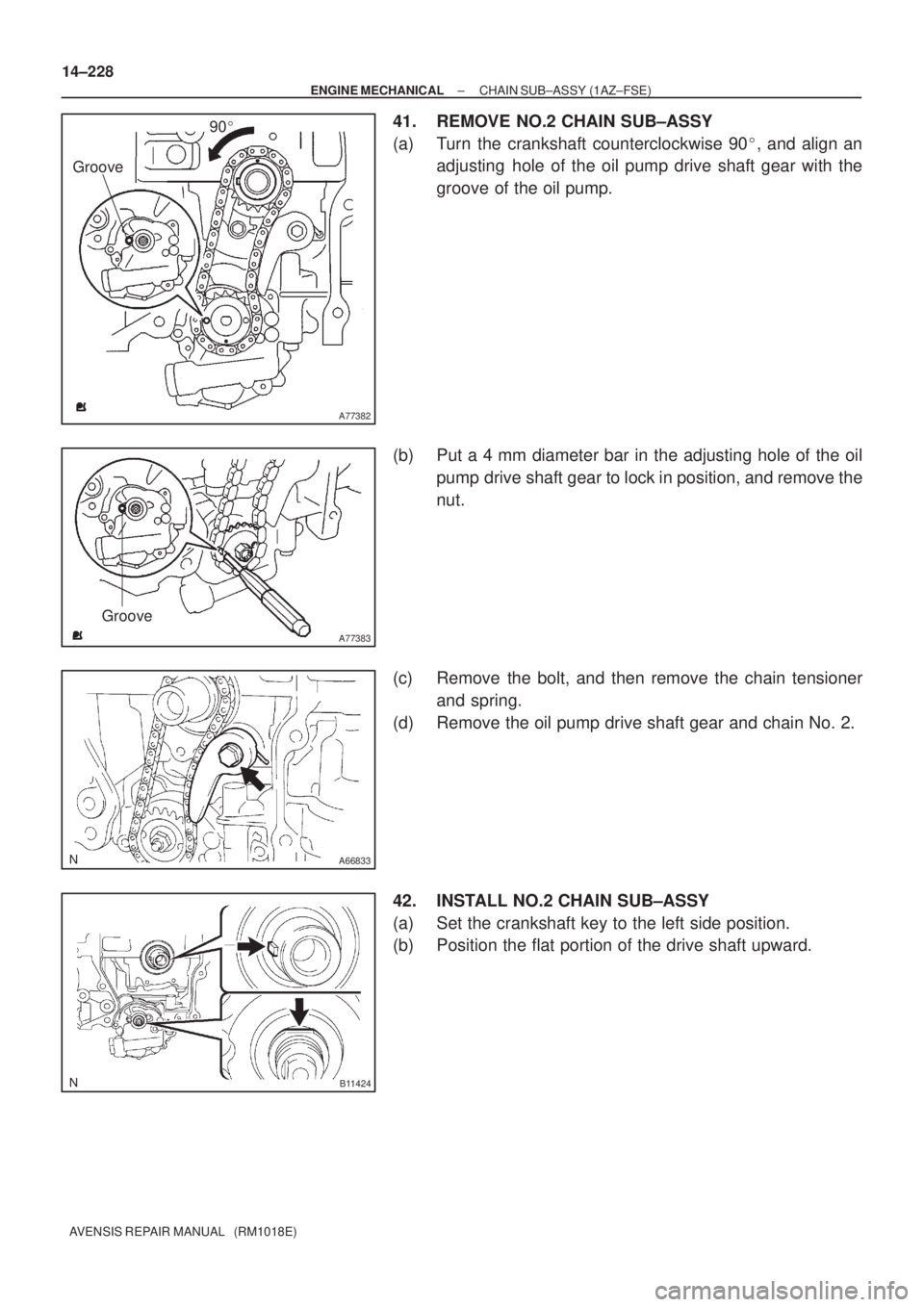
41. REMOVE NO.2 CHAIN SUB±ASSY
(a) Turn the crankshaft counterclockwise 90�, and align an
adjusting hole of the oil pump drive shaft gear with the
groove of the oil pump.
(b) Put a 4 mm diameter bar in the adjusting hole of the oil
pump drive shaft gear to lock in position, and remove the
nut.
(c) Remove the bolt, and then remove the chain tensioner
and spring.
(d) Remove the oil pump drive shaft gear and chain No. 2.
42. INSTALL NO.2 CHAIN SUB±ASSY
(a) Set the crankshaft key to the left side position.
(b) Position the flat portion of the drive shaft upward.
Page 2188 of 5135
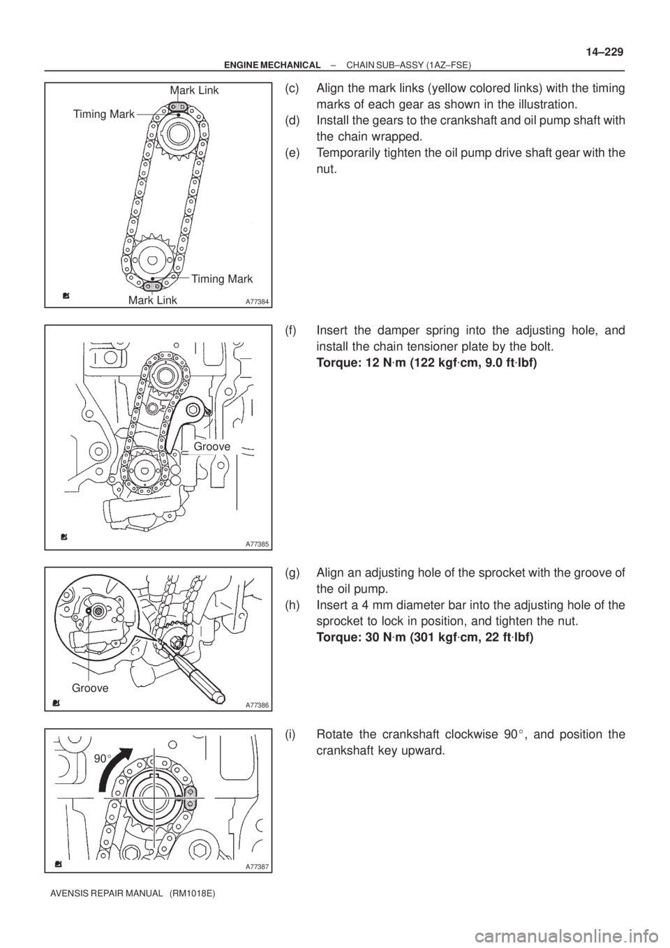
A77384
Mark Link
Timing Mark
Timing Mark
Mark Link
A77385
Groove
A77386
Groove
A77387
90�
± ENGINE MECHANICALCHAIN SUB±ASSY (1AZ±FSE)
14±229
AVENSIS REPAIR MANUAL (RM1018E)
(c) Align the mark links (yellow colored links) with the timing
marks of each gear as shown in the illustration.
(d) Install the gears to the crankshaft and oil pump shaft with
the chain wrapped.
(e) Temporarily tighten the oil pump drive shaft gear with the
nut.
(f) Insert the damper spring into the adjusting hole, and
install the chain tensioner plate by the bolt.
Torque: 12 N�m (122 kgf�cm, 9.0 ft�lbf)
(g) Align an adjusting hole of the sprocket with the groove of
the oil pump.
(h) Insert a 4 mm diameter bar into the adjusting hole of the
sprocket to lock in position, and tighten the nut.
Torque: 30 N�m (301 kgf�cm, 22 ft�lbf)
(i) Rotate the crankshaft clockwise 90�, and position the
crankshaft key upward.
Page 2199 of 5135
A77321
N´m (kgf´cm, ft´lbf)
: Specified torque
� Non±reusable part
43 (440, 32)
� Gasket
Chain Tensioner Assy No. 1
Timing Chain or Belt Cover
Sub±assy
Crankshaft Position
Sensor
9.0 (90, 80 in.�lbf)
V±ribbed Belt
Tensioner Assy
60 (610, 44)
60 (610, 44)
43 (440, 32)
43 (440, 32)
170 (1,735, 125)
Crank Shaft Pulley
� Oil Seal
43 (440, 32)
Chain Sub±assy
Chain Tensioner
Slipper
Chain Vibration
Damber No. 1
Crankshaft
Timing Gear
or Sprocket
19 (195, 14)
Crankshaft Position
Sensor Plate No. 1
Timing Chain Guide
Oil Pump
Drive Gear
12 (122, 9.0)
Spring
Chain Tensioner
Oil Pump Drive Shaft Gear
Oil Pan Sub±assy
9.0 (90, 80 in.�lbf)
9.0 (90, 80 in.�lbf)
9.0 (90, 80 in.�lbf)
30 (301, 22)
No. 2 Chain Sub±assy
9.0 (90, 80 in.�lbf)
9.0 (90, 80 in.�lbf)
± ENGINE MECHANICALCHAIN SUB±ASSY (1AZ±FSE)
14±221
AVENSIS REPAIR MANUAL (RM1018E)
Page 2206 of 5135

AVENSIS REPAIR MANUAL (RM1018E)
61.SEPARATE VANE PUMP ASSY
(a)Disconnect the PS oil pressure switch connector.
(b)Remove")
A77331
SST
A77353
14±210
±
ENGINE MECHANICAL PARTIAL ENGINE ASSY(1AZ±FSE)
AVENSIS REPAIR MANUAL (RM1018E)
61.SEPARATE VANE PUMP ASSY
(a)Disconnect the PS oil pressure switch connector.
(b)Remove the 2 bolts and separate the vane pump from the engine.
62.REMOVE STARTER ASSY (See page 19±12)
63. REMOVE FRONT SUSPENSION CROSSMEMBER W/CENTER MEMBER
(a) Remove the through bolt and nut from the engine mounting insulator FR.
(b) Remove the through bolt and nut from the engine mounting insulator RR.
64.REMOVE FRONT DRIVE SHAFT ASSY LH (See page 30±6)
65.REMOVE FRONT DRIVE SHAFT ASSY RH (See page 30±6)
66.REMOVE MANUAL TRANSAXLE ASSY (M/T TRANSAXLE) (See page 41±24)
67.REMOVE AUTOMATIC TRANSAXLE ASSY (A/T TRANSAXLE) (See page 40±25)
68.REMOVE CLUTCH COVER ASSY (M/T TRANSAXLE) (See page 42±26)
69.REMOVE CLUTCH DISC ASSY (M/T TRANSAXLE) (See page 42±26) 70. REMOVE DRIVE PLATE AND RING GEAR ORFLYWHEEL
(a) Using SST, fix the crankshaft pulley and remove the drive plate and ring gear or flywheel.
SST 09213±54015 (91651±60855), 09330±00021
71. REMOVE CAMSHAFT TIMING OIL CONTROL VALVE ASSY
(a) Remove the bolt, O±ring and the camshaft timing oil control valve.
72. REMOVE THROTTLE BODY BRACKET
(a) Separate the engine wire.
(b) Remove the 4 bolts and the throttle body bracket.
73.REMOVE THROTTLE BODY ASSY (See page 10±44)
74. REMOVE FUEL PRESSURE PULSATION DAMPER ASSY
75. DISCONNECT FUEL TUBE SUB±ASSY
76.REMOVE FUEL PIPE SUB±ASSY NO.1 (See page 11±52)
77.REMOVE FUEL PUMP ASSY (See page 11±52)
78. REMOVE WATER BY±PASS HOSE 79. REMOVE INTAKE MANIFOLD
(a) Remove the 5 bolts and 2 nuts.
(b) Remove the intake manifold and the insulator.
Page 2210 of 5135

AVENSIS REPAIR MANUAL (RM1018E)
121.INSTALL DRIVE PLATE AND RING GEAR OR FLYWHEEL
(a)Hold the cranks")
A77333SST
A77403
15
3
7
2
6
4 8
A63273
14±214
±
ENGINE MECHANICAL PARTIAL ENGINE ASSY(1AZ±FSE)
AVENSIS REPAIR MANUAL (RM1018E)
121.INSTALL DRIVE PLATE AND RING GEAR OR FLYWHEEL
(a)Hold the crankshaft with SST.
SST09213±54015 (91651±60855), 09330±00021
Adhesive:
Part No. 08833±00070, THREE BOND or equivalent
(b)Install the drive plate. (A/T) (1)Clean the bolt and bolt hole.
(2)Apply adhesive to the bolts.
(3)Using several steps, install and tighten the 8 bolts
uniformly in the sequence shown in the illustration.
Torque: 98 N �m (1,000 kgf �cm, 72 ft �lbf)
(c)Install the flywheel. (M/T) (1)Clean the bolt hole.
(2)Using several steps, install and tighten the 8 boltsuniformly in the sequence shown in the illustration.
Torque: 130 N �m (1,327 kgf �cm, 96 ft �lbf)
NOTICE:
Do not reuse the flywheel bolt.
122.INSTALL CLUTCH DISC ASSY (M/T TRANSAXLE) (See page 42±26)
123.INSTALL CLUTCH COVER ASSY (M/T TRANSAXLE) (See page 42±26)
124.INSTALL MANUAL TRANSAXLE ASSY (M/T TRANSAXLE) (See page 41±24)
125.INSTALL AUTOMATIC TRANSAXLE ASSY (A/T TRANSAXLE) (See page 40±25)
126.INSTALL FRONT DRIVE SHAFT ASSY LH (See page 30±6)
127.INSTALL FRONT DRIVE SHAFT ASSY RH (See page 30±6)
128.INSTALL FRONT SUSPENSION CROSSMEMBER W/CENTER MEMBER
(a)Install the engine mounting insulator FR with the through bolt and nut. Torque: 87 N �m (887 kgf �cm,64 ft �lbf)
(b)Install the engine mounting insulator RR with the through bolt and nut. Torque: 87 N �m (887 kgf �cm,64 ft �lbf)
129.INSTALL STARTER ASSY (See page 19±12)
130. INSTALL VANE PUMP ASSY Torque: 37 N �m (370 kgf �cm, 27 ft �lbf)
131. INSTALL ENGINE ASSEMBLY WITH TRANSAXLE
(a) Install the 2 bolts and 2 nuts as shown in the illustration. Torque:
Bolt 45 N �m (459 kgf �cm, 33 ft �lbf)
Nut 133 N �m (1,356 kgf �cm, 98 ft �lbf)
Page 2219 of 5135
A77315
87 (887, 64)
37 (377, 27)
52 (530, 38)
87 (887, 64)52 (530, 38)
52 (530, 38)
52 (530, 38)52 (530, 38)
52 (530, 38)
133 (1,356, 83)
80 (816, 59)
80 (816, 59)
133 (1,356, 83)
45 (459, 33)
133 (1,356, 83)
Engine Mounting Bracket No. 2 RH
Transverse Engine
Engine Mounting Insulator
Front Suspension Brace RH
Front Suspension
Brace LH
Front Drive Shaft Assy RH
Front Drive Shaft Assy LH Engine Assembly
with Transaxle
Front Suspension Crossmember
w/ Center Member
N´m (kgf´cm, ft´lbf)
: Specified torque
Vane Pump Assy
113 (1,152, 83)
87 (887, 64)
± ENGINE MECHANICALPARTIAL ENGINE ASSY (1AZ±FSE)
14±197
AVENSIS REPAIR MANUAL (RM1018E)

14±227
AVENSIS REPAIR MANUAL (RM1018E)
34. REMOVE TIMING CHAIN OR BELT COVER
SUB±ASSY
(a) Remove the 14 bolts and 2 nuts.
(b) Using")


37 (377, 27)
52 (530, 38)
87 (887, 64)52 (530, 38)
52 (530, 38)
52 (530, 38)52 (530, 38)
52 (530, 38)
133 (1,356, 83)
80 (816, 59)
80 (816, 59)
133 (1,356, 83)
45 (459, 33)
133 (1,")