Page 2032 of 5135

14±53
AVENSIS REPAIR MANUAL (RM1018E)
27. REMOVE CHAIN SUB�")
A30857
A10079
A62170
Set KeyUpward
A62171
Yellow
Color Link
Timing Mark
A62172
SST
± ENGINE MECHANICALCHAIN SUB±ASSY (1ZZ±FE/3ZZ±FE)
14±53
AVENSIS REPAIR MANUAL (RM1018E)
27. REMOVE CHAIN SUB±ASSY
(a) Remove the timing chain with the crankshaft timing gear
by plying it using screwdrivers as shown in the illustration.
NOTICE:
�Put shop rag to protect the engine.
�In case of revolving the camshafts with the chain off
the sprockets, turn the crankshaft 1/4 revolution
counterclockwise for valves not to touch the pistons.
28. INSTALL CHAIN SUB±ASSY
(a) Set No. 1 cylinder to TDC/compression.
(1) Turn the camshafts with a wrench and align the
point marks of the camshaft timing sprockets.
(2) Using a crankshaft pulley bolt, turn the crankshaft
and set the set key on the crankshaft upward.
(b) Install the timing chain to the crankshaft timing sprocket
with the yellow color link aligned with the timing mark on
the crankshaft timing sprocket.
HINT:
Three yellow color links are on the chain.
(c) Using SST, install the crankshaft timing sprocket.
SST 09223±22010
Page 2036 of 5135

14±57
AVENSIS REPAIR MANUAL (RM1018E)
38. INSTALL CRANKS")
A62837SST
A62180
Disconnect
Hook
Pin Turn
A62181
Plunger
Turn
Push
A62182
Seal Packing
± ENGINE MECHANICALCHAIN SUB±ASSY (1ZZ±FE/3ZZ±FE)
14±57
AVENSIS REPAIR MANUAL (RM1018E)
38. INSTALL CRANKSHAFT PULLEY
(a) Align the keyway of the pulley with the key located on the
crankshaft, and slide the pulley into place.
(b) Using SST, install the crankshaft pulley bolt.
SST 09960±10010 (09962±01000, 09963±01000)
Torque: 138 N�m (1,407 kgf�cm, 102 ft�lbf)
(c) Turn the crankshaft counterclockwise, and take the hook
off the knock pin to release the plunger.
(d) Turn the crankshaft clockwise, and check that the plunger
is extended.
HINT:
If the plunger does not be extended, press the slipper into the
chain tensioner using a screwdriver so that the hook is took off
from the knock pin and let the plunger can be extended.
39. INSTALL CYLINDER HEAD COVER SUB±ASSY
(a) Remove any old pacing (FIPG) material.
(b) Apply seal packing to the 2 locations as shown in the il-
lustration.
Seal packing: Part No. 08826±00080 or equivalent
NOTICE:
�Remove any oil from the contact surface.
�Install the cylinder head cover within 3 minutes after
applying seal packing.
�Do not expose the seal to engine oil 2 hours after
installing.
Page 2049 of 5135

14±33
AVENSIS REPAIR MANUAL (RM1018E)
60. REMOVE FRONT SUSPENSION CROSSMEMBER
W/CENTER MEMBER
(a) Remove")
A76718
A76719
A62838SST
A62838SST
±
ENGINE MECHANICAL PARTIAL ENGINE ASSY (1ZZ±FE/3ZZ±FE)
14±33
AVENSIS REPAIR MANUAL (RM1018E)
60. REMOVE FRONT SUSPENSION CROSSMEMBER
W/CENTER MEMBER
(a) Remove the through bolt and nut, detach the engine
mounting insulator FR from the engine mounting bracket.
(b) Remove the through bolt, detach the engine mounting in- sulator RR from the suspension crossmember.
(c) Separate the engine and the transaxle assembly from the suspension crossmember and the engine mounting
member.
61.REMOVE STARTER ASSY(See page 19±3)
62.REMOVE MANUAL TRANSAXLE ASSY (M/T TRANSAXLE) (See page 41±15)
63.REMOVE AUTOMATIC TRANSAXLE ASSY (A/T TRANSAXLE) (See page 40±11)
64.REMOVE CLUTCH COVER ASSY (M/T TRANSAXLE) (See page 42±26)
65.REMOVE CLUTCH DISC ASSY (M/T TRANSAXLE)(See page 42±26) 66. REMOVE FLYWHEEL SUB±ASSY (M/T TRANSAXLE)
(a) Hold the crankshaft with SST, remove the 8 bolts and theflywheel.
SST 09960±10010 (09962±01000, 09963±01000)
67. REMOVE DRIVE PLATE & RING GEAR SUB±ASSY (A/T TRANSAXLE)
(a) Hold the crankshaft with SST, remove the 8 bolts and the
drive plate & ring gear.
SST 09960±10010 (09962±01000, 09963±01000)
68. REMOVE IGNITION COIL ASSY
(a) Disconnect the 4 ignition coil connectors.
Page 2057 of 5135
A76713
A62838SST
A62205
1
5
3
82
6
4
7
A62206
90�
A62838SST
± ENGINE MECHANICALPARTIAL ENGINE ASSY (1ZZ±FE/3ZZ±FE)
14±41
AVENSIS REPAIR MANUAL (RM1018E)
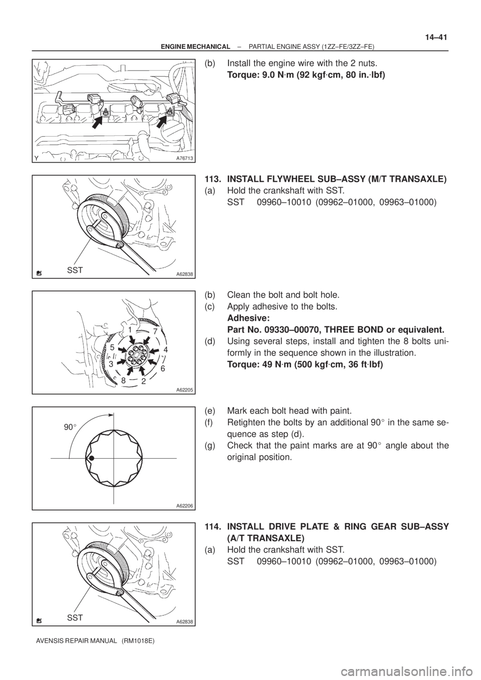
(b) Install the engine wire with the 2 nuts.
Torque: 9.0 N�m (92 kgf�cm, 80 in.�lbf)
113. INSTALL FLYWHEEL SUB±ASSY (M/T TRANSAXLE)
(a) Hold the crankshaft with SST.
SST 09960±10010 (09962±01000, 09963±01000)
(b) Clean the bolt and bolt hole.
(c) Apply adhesive to the bolts.
Adhesive:
Part No. 09330±00070, THREE BOND or equivalent.
(d) Using several steps, install and tighten the 8 bolts uni-
formly in the sequence shown in the illustration.
Torque: 49 N�m (500 kgf�cm, 36 ft�lbf)
(e) Mark each bolt head with paint.
(f) Retighten the bolts by an additional 90� in the same se-
quence as step (d).
(g) Check that the paint marks are at 90� angle about the
original position.
114. INSTALL DRIVE PLATE & RING GEAR SUB±ASSY
(A/T TRANSAXLE)
(a) Hold the crankshaft with SST.
SST 09960±10010 (09962±01000, 09963±01000)
Page 2064 of 5135
A76704
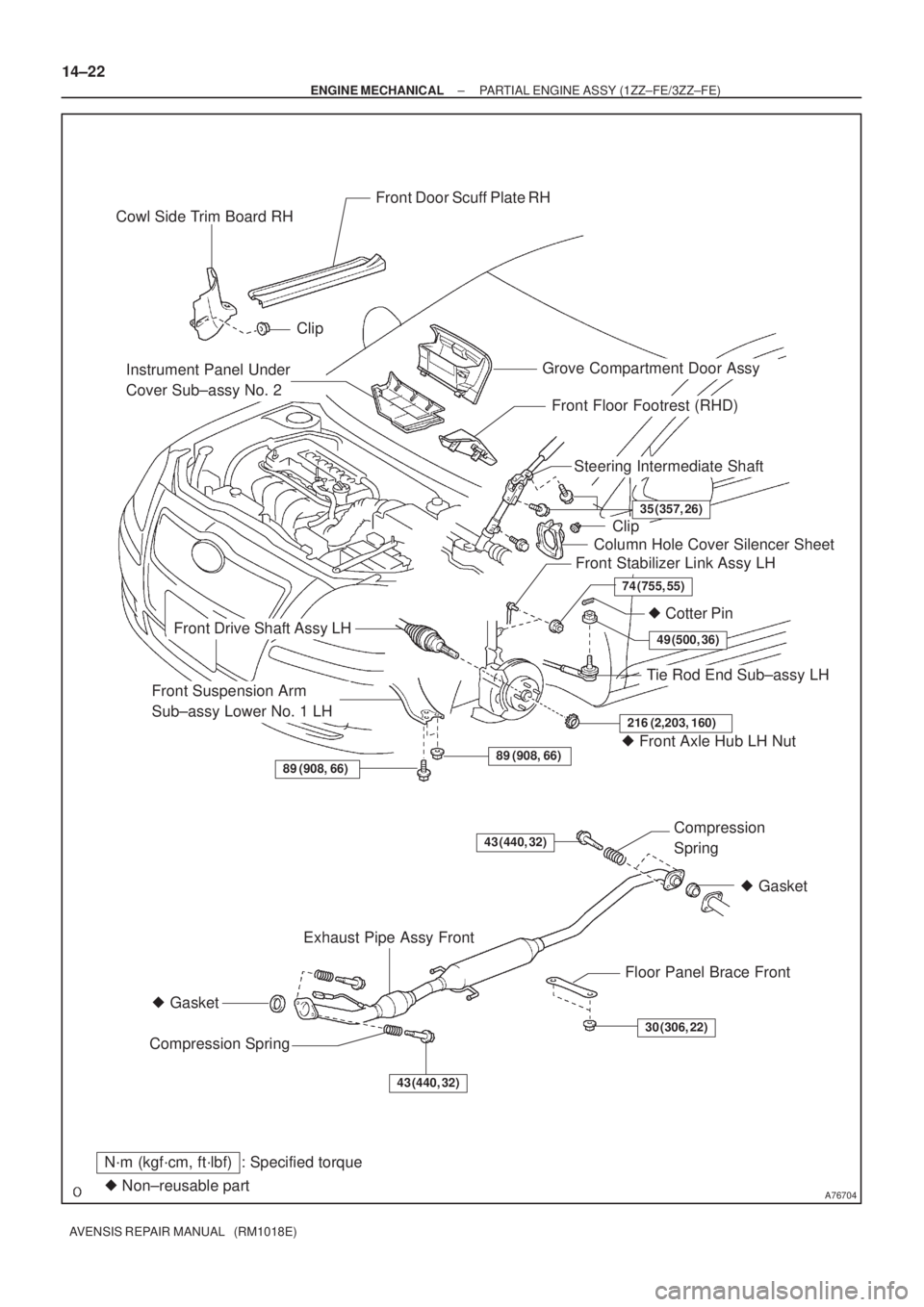
Grove Compartment Door Assy Cowl Side Trim Board RH
Front Door Scuff Plate RH
Clip
Clip
Column Hole Cover Silencer Sheet
Steering Intermediate Shaft
� Cotter Pin
Tie Rod End Sub±assy LH
Front Suspension Arm
Sub±assy Lower No. 1 LH
Front Drive Shaft Assy LH
Front Stabilizer Link Assy LH
Exhaust Pipe Assy Front
Floor Panel Brace FrontCompression
Spring
Compression Spring� Gasket
� Gasket
89 (908, 66)
216 (2,203, 160)
49 (500, 36)
74 (755, 55)
35 (357, 26)
89 (908, 66)� Front Axle Hub LH Nut
� Non±reusable part
N´m (kgf´cm, ft´lbf) : Specified torque
43 (440, 32)
30 (306, 22)
43 (440, 32)
Front Floor Footrest (RHD)
Instrument Panel Under
Cover Sub±assy No. 2
14±22
± ENGINE MECHANICALPARTIAL ENGINE ASSY (1ZZ±FE/3ZZ±FE)
AVENSIS REPAIR MANUAL (RM1018E)
Page 2075 of 5135

14±127
AVENSIS REPAIR MANUAL (RM1018E)
63.SEPARATE VANE PUMP ASSY
(a)Disconnect the PS oil pressure switch connector.
(b)Remove th")
A77402SST
A56446
±
ENGINE MECHANICAL PARTIAL ENGINE ASSY(1AZ±FE)
14±127
AVENSIS REPAIR MANUAL (RM1018E)
63.SEPARATE VANE PUMP ASSY
(a)Disconnect the PS oil pressure switch connector.
(b)Remove the 2 bolts and separate the vane pump from the engine.
64.REMOVE STARTER ASSY (See page 19±12)
65.REMOVE FRONT SUSPENSION CROSSMEMBER W/CENTER MEMBER
(a)Remove the through bolt and nut from the engine mounting insulator FR.
(b)Remove the through bolt and nut from the engine mounting insulator RR.
66.REMOVE FRONT DRIVE SHAFT ASSY LH (See page 30±6)
67.REMOVE FRONT DRIVE SHAFT ASSY RH (See page 30±6)
68.REMOVE MANUAL TRANSAXLE ASSY (M/T TRANSAXLE) (See page 41±24)
69.REMOVE AUTOMATIC TRANSAXLE ASSY (A/T TRANSAXLE) (See page 40±25)
70.REMOVE CLUTCH COVER ASSY (M/T TRANSAXLE) (See page 42±26)
71.REMOVE CLUTCH DISC ASSY (M/T TRANSAXLE) (See page 42±26)
72. REMOVE DRIVE PLATE AND RING GEAR ORFLYWHEEL
(a) Using SST, fix the crankshaft pulley and remove the drive plate and ring gear or flywheel.
SST 09213±54015 (91651±60855), 09330±00021
73. REMOVE CAMSHAFT TIMING OIL CONTROL VALVE ASSY (W/ VVT±i)
(a) Remove a bolt, O±ring and the camshaft timing oil control valve. 74. REMOVE INTAKE MANIFOLD
(a) Remove the 5 bolts and 2 nuts, and then remove the in-take manifold.
75. REMOVE VENTILATION HOSE
76. REMOVE VENTILATION HOSE NO.2
77. REMOVE ENGINE WIRE
78. REMOVE INTAKE MANIFOLD INSULATOR NO.1
79. REMOVE OIL LEVEL GAGE SUB±ASSY
80. REMOVE OIL LEVEL GAGE GUIDE
81. REMOVE MANIFOLD CONVERTER INSULATOR NO.1
(a) Remove the 4 bolts and the manifold converter insulator No. 1.
Page 2076 of 5135

AVENSIS REPAIR MANUAL (RM1018E)
82.REMOVE EXHAUST MANIFOLD CONVERTER SUB±ASSY
(a)Remove the")
A60067
A52497
A32676
A78645
Oil Pressure Switch
14±128
±
ENGINE MECHANICAL PARTIAL ENGINE ASSY(1AZ±FE)
AVENSIS REPAIR MANUAL (RM1018E)
82.REMOVE EXHAUST MANIFOLD CONVERTER SUB±ASSY
(a)Remove the 3 bolts and 2 nuts, and then detach the No.
1 and No. 2 exhaust manifold stays.
(b)Remove the 5 nuts, and then remove the exhaust man- ifold converter and gasket.
83.REMOVE WATER INLET
(a)Remove the 2 nuts and the water inlet.
84.REMOVE THERMOSTAT
85.REMOVE IGNITION COIL ASSY
(a)Remove the 4 bolts and the 4 ignition coils. 86.REMOVE V±RIBBED BELT TENSIONER ASSY
(a)Remove the bolt and nut, and then remove the V±ribbedbelt tensioner.
87.REMOVE DRIVE SHAFT BEARING BRACKET
(a)Remove the 3 bolts and the drive shaft bearing bracket.
88.REMOVE FUEL DELIVERY PIPE W/INJECTOR (See page 11±26)
89. REMOVE WATER BY±PASS PIPE NO.1
(a) Remove the bolt and 2 nuts, and then detach the water by±pass pipe No\
. 1. 90. REMOVE ENGINE OIL PRESSURE SWITCH ASSY
(a) Using SST, remove the engine oil pressure switch.SST 09268±46021
Page 2077 of 5135

14±129
AVENSIS REPAIR MANUAL (RM1018E)
91.REMOVE KNOCK SENSOR
(a)Remove the nut and the knock sensor.
92.REMOVE ENGINE COOLANT TEMPER")
A77332
23
145
±
ENGINE MECHANICAL PARTIAL ENGINE ASSY(1AZ±FE)
14±129
AVENSIS REPAIR MANUAL (RM1018E)
91.REMOVE KNOCK SENSOR
(a)Remove the nut and the knock sensor.
92.REMOVE ENGINE COOLANT TEMPERATURE SENSOR
(a)Using SST, remove the engine coolant temperature sensor.
SST09817±33190
93.REPLACE PARTIAL ENGINE ASSY
94.INSTALL ENGINE COOLANT TEMPERATURE SENSOR
(a)Install a new gasket to the engine coolant temperature sensor.
(b)Install the engine coolant temperature sensor. Torque: 20 N �m (208 kgf �cm,15 ft �lbf)
SST09817±33190
95.INSTALL KNOCK SENSOR
Torque: 20 N �m (208 kgf �cm,15 ft �lbf)
96.INSTALL ENGINE OIL PRESSURE SWITCH ASSY
(a)Clean the threads of the oil pressure switch, apply adhesive there. Adhesive: Part No. 08833±00080 THREE BOND 1344 or equivalent
(b)Install the oil pressure switch. Torque: 15 N �m (153 kgf �cm,11 ft �lbf)
97.INSTALL WATER BY±PASS PIPE NO.1
(a)Install a new gasket and the water by±pass pipe No. 1 with the bolt a\
nd 2 nuts. Torque: 9.0 N �m (92 kgf �cm,80 in. �lbf)
98.INSTALL FUEL DELIVERY PIPE W/INJECTOR (See page 11±26)
99.INSTALL DRIVE SHAFT BEARING BRACKET Torque: 54 N �m (551 kgf �cm,40 ft �lbf)
100.INSTALL V±RIBBED BELT TENSIONER ASSY
Torque: 60 N �m (607 kgf �cm,44 ft �lbf)
101.INSTALL IGNITION COIL ASSY Torque: 9.0 N �m (92 kgf �cm,80 in. �lbf)
102.INSTALL THERMOSTAT (See page 16±23)
103. INSTALL WATER INLET
Torque: 9.0 N �m (92 kgf �cm, 80 in. �lbf)
104. I N S TA L L E X HAUST MANIFOLD CONVERTER
SUB±ASSY
(a) Install a new gasket and the exhaust manifold converter
with the 5 nuts.
Torque: 37 N �m (378 kgf �cm, 27 ft �lbf)