Page 2079 of 5135

14±131
AVENSIS REPAIR MANUAL (RM1018E)
(b)Install the drive plate. (A/T)
(1)Clean the bolt and bol")
A77403
15
3
7
2
6
4 8
A63273
A77404
B
A
BBBB
A
B
±
ENGINE MECHANICAL PARTIAL ENGINE ASSY(1AZ±FE)
14±131
AVENSIS REPAIR MANUAL (RM1018E)
(b)Install the drive plate. (A/T)
(1)Clean the bolt and bolt hole.
(2)Apply adhesive to the bolts.
(3)Using several steps, install and tighten the 8 boltsuniformly in the sequence shown in the illustration.
Torque: 98 N �m (1,000 kgf �cm, 72 ft �lbf)
(c)Install the flywheel. (M/T)
(1)Clean the bolt hole.
(2)Using several steps, install and tighten the 8 boltsuniformly in the sequence shown in the illustration.
Torque: 130 N �m (1,327 kgf �cm, 96 ft �lbf)
NOTICE:
Do not reuse the flywheel bolt.
110.INSTALL CLUTCH DISC ASSY (M/T TRANSAXLE) (See page 42±26)
111.INSTALL CLUTCH COVER ASSY (M/T TRANSAXLE) (See page 42±26)
112.INSTALL MANUAL TRANSAXLE ASSY (M/T TRANSAXLE) (See page 41±24)
113.INSTALL AUTOMATIC TRANSAXLE ASSY (A/T TRANSAXLE) (See page 40±25)
114.INSTALL FRONT DRIVE SHAFT ASSY LH (See page 30±6)
115.INSTALL FRONT DRIVE SHAFT ASSY RH (See page 30±6)
116.INSTALL FRONT SUSPENSION CROSSMEMBER W/CENTER MEMBER
(a)Install the engine mounting insulator FR with the through bolt and nut. Torque: 87 N �m (887 kgf �cm,64 ft �lbf)
(b)Install the engine mounting insulator RR with the through bolt and nut. Torque: 87 N �m (887 kgf �cm,64 ft �lbf)
117.INSTALL STARTER ASSY (See page 19±12)
118. INSTALL VANE PUMP ASSY
Torque: 37 N �m (370 kgf �cm, 27 ft �lbf)
119. INSTALL ENGINE ASSEMBLY WITH TRANSAXLE
(a) Install the 2 bolts and 2 nuts as shown in the illustration. Torque:
Bolt 45 N �m (459 kgf �cm, 33 ft �lbf)
Nut 133 N �m (1,356 kgf �cm, 98 ft �lbf)
(b) Install the front suspension member braces with the 8 bolts.
Torque:
Bolt A 133 N �m (1,356 kgf �cm, 98 ft �lbf)
Bolt B 80 N �m (816 kgf �cm, 59 ft �lbf)
Page 2088 of 5135
A77315
87 (887, 64)
37 (377, 27)
52 (530, 38)
87 (887, 64)52 (530, 38)
52 (530, 38)
52 (530, 38)52 (530, 38)
52 (530, 38)
133 (1,356, 83)
80 (816, 59)
80 (816, 59)
133 (1,356, 83)
45 (459, 33)
133 (1,356, 83)
Engine Mounting Bracket No. 2 RH
Transverse Engine
Engine Mounting Insulator
Front Suspension Brace RH
Front Suspension
Brace LH
Front Drive Shaft Assy RH
Front Drive Shaft Assy LH Engine Assembly
with Transaxle
Front Suspension Crossmember
w/ Center Member
N´m (kgf´cm, ft´lbf)
: Specified torque
Vane Pump Assy
113 (1,152, 83)
87 (887, 64)
14±116
± ENGINE MECHANICALPARTIAL ENGINE ASSY (1AZ±FE)
AVENSIS REPAIR MANUAL (RM1018E)
Page 2089 of 5135
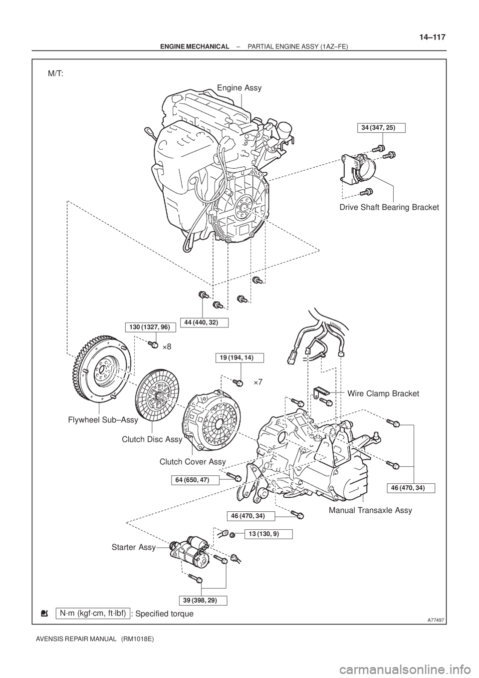
A77497
Engine Assy
Drive Shaft Bearing Bracket
Wire Clamp Bracket
Manual Transaxle Assy
Starter AssyClutch Disc Assy Flywheel Sub±Assy�8
�7
Clutch Cover Assy
N´m (kgf´cm, ft´lbf)
: Specified torque M/T:
34 (347, 25)
46 (470, 34)
13 (130, 9)
39 (398, 29)
64 (650, 47)
19 (194, 14)
44 (440, 32)
46 (470, 34)
130 (1327, 96)
± ENGINE MECHANICALPARTIAL ENGINE ASSY (1AZ±FE)
14±117
AVENSIS REPAIR MANUAL (RM1018E)
Page 2090 of 5135
A77316
Engine Assy
Drive Shaft Bearing Bracket
Hole Plug
Drive Plate & Ring Gear
Sub±Assyx6
Wire Clamp Bracket
Starter Wire Starter Assy
34 (347, 25)
41 (420, 32)
98 (1,000, 72)
46 (469, 34)
13 (132, 10)
x8
N´m (kgf´cm, ft´lbf)
: Specified torque A/T:
Automatic Transaxle
46 (469, 34)
46 (469, 34)
37 (378, 27)
37 (378, 27)
64 (653, 47)
41 (418, 30)
14±118
± ENGINE MECHANICALPARTIAL ENGINE ASSY (1AZ±FE)
AVENSIS REPAIR MANUAL (RM1018E)
Page 2103 of 5135

AVENSIS REPAIR MANUAL (RM1018E)
ENGINE REAR OIL SEAL(1ZZ±FE/3ZZ±FE)
R")
141CO±01
A62838SST
A62838SST
A62202
Cut Position
A62203
SST
14±98
±
ENGINE MECHANICAL ENGINE REAR OIL SEAL(1ZZ±FE/3ZZ±FE)
AVENSIS REPAIR MANUAL (RM1018E)
ENGINE REAR OIL SEAL(1ZZ±FE/3ZZ±FE)
REPLACEMENT
1.REMOVE MANUAL TRANSAXLE ASSY (M/T TRANSAXLE) (See page 41±15)
2.REMOVE AUTOMATIC TRANSAXLE ASSY (A/T TRANSAXLE) (See page 40±11)
3.REMOVE CLUTCH COVER ASSY (M/T TRANSAXLE) (See page 42±26)
4.REMOVE CLUTCH DISC ASSY (M/T TRANSAXLE) (See page 42±26) 5. REMOVE FLYWHEEL SUB±ASSY (M/T TRANSAXLE)
(a) Hold the crankshaft with SST, remove the 8 bolts and theflywheel.
SST 09960±10010 (09962±01000, 09963±01000)
6. REMOVE DRIVE PLATE & RING GEAR SUB±ASSY (A/T TRANSAXLE)
(a) Hold the crankshaft with SST, remove the 8 bolts and the drive plate & ring gear.
SST 09960±10010 (09962±01000, 09963±01000)
7. REMOVE ENGINE REAR OIL SEAL
(a) Using a knife, cut off the oil seal lip.
(b) Using a screwdriver with the tip wrapped in tape, pry out the oil seal.
NOTICE:
After the removal, check if the crankshaft is not damaged.
If it is damaged, smooth the surface with 400±grid sandpa-
per.
8. INSTALL ENGINE REAR OIL SEAL
(a) Apply MP grease to a new oil seal lip.
NOTICE:
Keep the lip off foreign materials.
(b) Using SST, tap in the oil seal until its surface is flush with the rear oil seal retainer edge.
SST 09223±15020, 09950±70010 (09951±07100)
NOTICE:
Wipe off extra grease on the crankshaft.
Page 2104 of 5135

14±99
AVENSIS REPAIR MANUAL (RM1018E)
9.INSTALL FLYWHEEL SUB±")
A62838SST
A62205
1
5
3
82
6
4
7
A62206
90 �
A62838SST
A62204
1
5
3
82
6
4
7
±
ENGINE MECHANICAL ENGINE REAR OIL SEAL(1ZZ±FE/3ZZ±FE)
14±99
AVENSIS REPAIR MANUAL (RM1018E)
9.INSTALL FLYWHEEL SUB±ASSY (M/T TRANSAXLE)
(a)Fix the crankshaft with SST.
SST09960±10010 (09962±01000, 09963±01000)
(b)Clean the bolt and bolt hole.
(c)Apply adhesive to the bolts. Adhesive:
Part No. 09330±00070, THREE BOND or equivalent.
(d)Using several steps, Install and tighten the 8 bolts uni- formly in the sequence shown in the illustration.
Torque: 49 N �m (500 kgf �cm, 36 ft �lbf)
(e)Mark the bolts with paint as shown in the illustration.
(f)Retighten the bolts by an additional 90 � in the same se-
quence as step (d).
(g)Check that the paint marks of each bolt are at 90 � angle
from the original position.
10.INSTALL CLUTCH DISC ASSY (M/T TRANSAXLE) (See page 42±26)
11. INSTALL CLUTCH COVER ASSY (M/T TRANSAXLE) (See page 42±26)
12. INSTALL DRIVE PLATE & RING GEAR SUB±ASSY (A/T TRANSAXLE)
(a) Fix the crankshaft with SST. SST 09960±10010 (09962±01000, 09963±01000)
(b) Clean the bolt and bolt hole.
(c) Apply adhesive to the bolts. Adhesive:
Part No. 09330±00070, THREE BOND or equivalent.
(d) Using several steps, install and tighten the 8 bolts uni- formly in the sequence shown in the illustration.
(e) Fix the crankshaft with SST.
Torque: 88 N �m (897 kgf �cm, 65 ft �lbf)
Page 2107 of 5135
14±97
AVENSIS REPAIR MANUAL (RM1018E)
9. REMOVE TIMING GEAR COVER OIL SE")
A62183
Cut Position
Pry
A62184
SST
A62837SST
A64005
± ENGINE MECHANICALTIMING CHAIN OR BELT COVER OIL
SEAL (1ZZ±FE/3ZZ±FE)14±97
AVENSIS REPAIR MANUAL (RM1018E)
9. REMOVE TIMING GEAR COVER OIL SEAL
(a) Using a knife, cut off the oil seal lip.
(b) Using a screwdriver with the tip wrapped in tape, pry out
the oil seal.
NOTICE:
After the removal, check if the crankshaft is not damaged.
If it is damaged, smooth the surface with 400±grit sandpa-
per.
10. INSTALL TIMING GEAR COVER OIL SEAL
(a) Apply MP grease to a new oil seal lip.
NOTICE:
Keep the lip free of foreign objects.
(b) Using SST, tap in the oil seal until its surface is flush with
the timing chain cover edge.
SST 09223±22010
NOTICE:
Wipe off extra grease on the crankshaft.
11. INSTALL CRANKSHAFT PULLEY
(a) Align the keyway of the pulley with the key located on the
crankshaft and slide the pulley into place.
(b) Using SST, install the crankshaft pulley bolt.
SST 09960±10010 (09962±01000, 09963±01000)
Torque: 138 N�m (1,407 kgf�cm, 102 ft�lbf)
12. INSTALL ENGINE MOUNTING INSULATOR
SUB±ASSY RH
(a) Install the engine mounting insulator with the 4 bolts and
2 nuts.
Torque: 52 N�m (530 kgf�cm, 38 ft�lbf)
13. INSTALL FRONT WHEEL RH
Torque: 103 N�m (1,050 kgf�cm, 76 ft�lbf)
14. CHECK FOR ENGINE OIL LEAKS
Page 2113 of 5135

AVENSIS REPAIR MANUAL (RM1018E)
38. REMOVE TRANSVERSE ENGINE ENGINE
MOUNTING BRACKET
(a) Rem")
A12816
A76692
A62178
Push
A10076
A30848
14±86
± ENGINE MECHANICALCYLINDER HEAD GASKET (1ZZ±FE/3ZZ±FE)
AVENSIS REPAIR MANUAL (RM1018E)
38. REMOVE TRANSVERSE ENGINE ENGINE
MOUNTING BRACKET
(a) Remove the 3 bolts and the transverse engine engine
mounting bracket.
39. REMOVE CRANKSHAFT POSITION SENSOR
(a) Remove the 2 bolts which are used to secure the crank-
shaft position sensor.
40. REMOVE CHAIN TENSIONER ASSY NO.1
(a) Remove the 2 nuts and the chain tensioner.
NOTICE:
Do not revolve the crankshaft without the chain tensioner.
41. REMOVE TIMING CHAIN OR BELT COVER
SUB±ASSY
(a) Remove the 11 bolts and nuts.
(b) Using a torx wrench socket (E8), remove the stud bolt.
(c) Remove the timing chain cover by prying between the cyl-
inder head and the cylinder block with a screwdriver.
NOTICE:
Be careful not to damage the timing chain cover, the cylin-
der head and the cylinder block.
42. REMOVE TIMING GEAR COVER OIL SEAL
(a) Using a screwdriver, remove the oil seal.
43. REMOVE CRANKSHAFT POSITION SENSOR PLATE
NO.1
44. REMOVE CHAIN TENSIONER SLIPPER
(a) Remove the bolt and the chain tensioner slipper.
45. REMOVE CHAIN VIBRATION DAMPER NO.1
(a) Remove the 2 bolt and the chain vibration damper.

37 (377, 27)
52 (530, 38)
87 (887, 64)52 (530, 38)
52 (530, 38)
52 (530, 38)52 (530, 38)
52 (530, 38)
133 (1,356, 83)
80 (816, 59)
80 (816, 59)
133 (1,356, 83)
45 (459, 33)
133 (1,")

41 (420, 32)
98 (1,000, 72)
46 (469, 34)
13 (132")