Page 500 of 5135
05±328
±
DIAGNOSTICS SFI SYSTEM(1AZ±FSE)
AVENSIS REPAIR MANUAL (RM1018E)
9REPLACE CAMSHAFT TIMING GEAR ASSY (See page 14±240)
GO
10CHECK BLOCKAGE(OCV, OIL CHECK VALVE AND OIL HOLE)
NGREPAIR OR REPLACE
OK
11CHECK IF DTC OUTPUTS REOCCUR
(a)Clear the DTC. (1)Operating the hand±held tester to erase the codes, or disconnecting the batter\
y terminal or the
EFI and ETCS fuses for 60 seconds or more.
(b)Start the engine and warm it up.
(c)Drive the vehicle around for 10 minutes or more.
(d)Read output DTC using the hand±held tester.
Standard: No DTC output.
HINT:
*: DTCs P0011 or P0012 is output when a foreign object in engine oil is caught in so\
me part of the system.
These codes will stay registered even if the system returns to normal after a\
short time. These foreign objects
are then captured by the oil filter, thus eliminating the source of the problem.
OKVVT SYSTEM OK
NG
CHECK AND REPLACE ECM (See page 01±32)
Page 515 of 5135

05±415
AVENSIS REPAIR MANUAL (RM1018E)
DTC P0200 INJECTOR CIRCUIT / OPEN
DTC P0201 INJECTOR CIRCUIT / OPEN ± (CYLINDER 1)
DTC P0202 INJECTOR CIRCUIT / OPEN ± (")
± DIAGNOSTICSSFI SYSTEM (1AZ±FSE)
05±415
AVENSIS REPAIR MANUAL (RM1018E)
DTC P0200 INJECTOR CIRCUIT / OPEN
DTC P0201 INJECTOR CIRCUIT / OPEN ± (CYLINDER 1)
DTC P0202 INJECTOR CIRCUIT / OPEN ± (CYLINDER 2)
DTC P0203 INJECTOR CIRCUIT / OPEN ± (CYLINDER 3)
DTC P0204 INJECTOR CIRCUIT / OPEN ± (CYLINDER 4)
CIRCUIT DESCRIPTION
The Electronic Driver Unit (EDU) has been adopted to operate the injector at high speed. The EDU enables
the injector to drive in high±speed rate under high±pressure fuel condition using its internal DC/DC converter
that provides high voltage and quick±charging system.
The ECM constantly monitors the EDU. If the ECM detects abnormal condition, it will stop the engine.
DTC No.DTC Detection ConditionTrouble Area
P0200
No IJF signals to ECM despite crankshaft rotating 10 times
(1 trip detection logic).
P0200No IJF signals to ECM despite crankshaft rotating 20 times
during cranking (2 trip detection logic).�Open or short in EDU circuit
�EDU (Injector driver)
P0201
P0202
P0203
P0204
No IJF signals of each cylinder to ECM 20 times successively
(1 trip detection logic).
(j )
�Fuel injector assy
�ECM
05CKG±01
Page 1910 of 5135

11±69
AVENSIS REPAIR MANUAL (RM1018E)
REPLACEMENT
1.REMOVE FRONT WHEEL RH
2.DRAIN ENGINE COOLANT(See page 16±44)
3.REMOVE ENGINE UN")
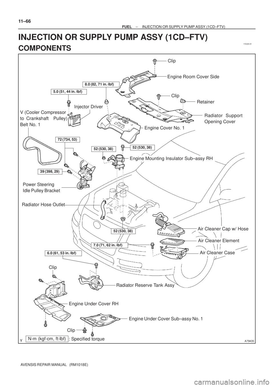
110UA±01
A15950
±
FUEL INJECTION OR SUPPLY PUMP ASSY(1CD±FTV)
11±69
AVENSIS REPAIR MANUAL (RM1018E)
REPLACEMENT
1.REMOVE FRONT WHEEL RH
2.DRAIN ENGINE COOLANT(See page 16±44)
3.REMOVE ENGINE UNDER COVER SUB±ASSY NO.1
4.REMOVE ENGINE UNDER COVER RH
5.REMOVE RADIATOR SUPPORT OPENING COVER
6.REMOVE ENGINE ROOM COVER SIDE
7.REMOVE AIR CLEANER ASSY (See page 11±60)
8.REMOVE ENGINE COVER NO.1
(a)Remove the 5 nuts and the engine cover.
9.REMOVE RADIATOR RESERVE TANK ASSY(See page 16±50)
10.DISCONNECT RADIATOR HOSE OUTLET
(a)Disconnect the radiator hose outlet from the water inlet.
11.REMOVE V (COOLER COMPRESSOR TO CRANKSHAFT PULLEY) BELT NO.1
(See page 14±269)
12.REMOVE GENERATOR V BELT (See page 14±269)
13.REMOVE INJECTOR DRIVER
(a)Remove the 2 nuts which are used to secure the injector driver.
(b)Disconnect the injector driver connector and the harness clamp.
(c)Remove the injector driver.
14.REMOVE ENGINE MOUNTING INSULATOR SUB±ASSY RH(See page 14±307)
15.REMOVE CRANKSHAFT PULLEY(See page 14±307)
SST09213±54015 (90105±08076), 09330±00021, 09950±50013 (0995\
1±05010, 09952±05010, 09953±05020, 09954±05031)
16.REMOVE IDLER PULLEY SUB±ASSY
(a)Remove the bolt and washer, then remove the idler pulley.
17.REMOVE TIMING BELT NO.2 COVER(See page 14±307)
18.REMOVE TIMING BELT NO.1 COVER(See page 14±307)
19. REMOVE TIMING BELT GUIDE
20. REMOVE TRANSVERSE ENGINE ENGINE MOUNTING BRACKET
(a) Remove the 6 bolts and the engine mounting bracket.
21.SET NO. 1 CYLINDER TO TDC/COMPRESSION(See page 14±307)
22.REMOVE TIMING CHAIN COVER PLATE(See page 14±307)
23.REMOVE TIMING BELT(See page 14±307)
Page 1916 of 5135

11±75
AVENSIS REPAIR MANUAL (RM1018E)
52.INSTALL TIMING BELT GUIDE(See page 14±307)
53.INSTALL TIMING BELT NO.1 COVER(See page 14±307)
54.INSTALL")
±
FUEL INJECTION OR SUPPLY PUMP ASSY (1CD±FTV)
11±75
AVENSIS REPAIR MANUAL (RM1018E)
52.INSTALL TIMING BELT GUIDE(See page 14±307)
53.INSTALL TIMING BELT NO.1 COVER(See page 14±307)
54.INSTALL TIMING BELT NO.2 COVER(See page 14±307)
55. INSTALL IDLER PULLEY SUB±ASSY
Torque: 40 N �m (408 kgf �cm, 30 ft �lbf)
56.INSTALL CRANKSHAFT PULLEY(See page 14±307) SST 09213±54015 (90105±08076), 09330±00021
57.INSTALL ENGINE MOUNTING INSULATOR SUB±ASSY RH(See page 14±307)
58. INSTALL INJECTOR DRIVER Torque: 5.0 N �m (51 kgf �cm, 44 in. �lbf)
59. ADJUST V (COOLER COMPRESSOR TO CRANKSHAFT PULLEY) BELT NO.1 (See page 14±269)
60.INSTALL RADIATOR RESERVE TANK ASSY(See page 16±50)
61. INSTALL ENGINE COVER NO.1 Torque: 8.0 N �m (82 kgf �cm, 71 in. �lbf)
62.INSTALL AIR CLEANER ASSY (See page 11±60)
63. INSTALL FRONT WHEEL RH
Torque: 103 N �m (1,050 kgf �cm, 76 ft �lbf)
64.ADD ENGINE COOLANT(See page 16±44)
65.CHECK FOR ENGINE COOLANT LEAKS(See page 16±37)
66.CHECK FOR FUEL LEAKS(See page 11±60)
Page 1917 of 5135
110U9±01
A79435
Air Cleaner Cap w/ Hose
Air Cleaner Element
Air Cleaner Case
7.0 (71, 62 in.�lbf)
N´m (kgf´cm, ft´lbf)
: Specified torque
Radiator Hose Outlet
Clip
Engine Room Cover Side
Clip
Retainer
Radiator Support
Opening Cover
8.0 (82, 71 in.�lbf)
5.0 (51, 44 in.�lbf)
V (Cooler Compressor
to Crankshaft Pulley)
Belt No. 1
Injector Driver
72 (734, 53)
52 (530, 38)52 (530, 38)
Engine Cover No. 1
Engine Mounting Insulator Sub±assy RH
39 (398, 29)
Power Steering
Idle Pulley Bracket
52 (530, 38)
Clip
Engine Under Cover RH
Engine Under Cover Sub±assy No. 1
Clip
Radiator Reserve Tank Assy
6.0 (61, 53 in.�lbf)
11±66
± FUELINJECTION OR SUPPLY PUMP ASSY (1CD±FTV)
AVENSIS REPAIR MANUAL (RM1018E)
INJECTION OR SUPPLY PUMP ASSY (1CD±FTV)
COMPONENTS
Page 1982 of 5135
A62180
Disconnect
Hook
Pin Turn
A62181
Plunger
Turn
Push
A11858
A64005
14±16
± ENGINE MECHANICALVALVE CLEARANCE (1ZZ±FE/3ZZ±FE)
AVENSIS REPAIR MANUAL (RM1018E)
(3) Turn the crankshaft counterclockwise, and take the
hook off the knock pin to release the plunger.
(4) Turn the crankshaft clockwise, and check that the
plunger is extended.
HINT:
If the plunger does not be extended, press the slipper into the
chain tensioner using a screwdriver so that the hook is took off
from the knock pin and let the plunger can be extended.
16. INSTALL V±RIBBED BELT TENSIONER ASSY
(a) Install the V±ribbed belt tensioner with the nut and bolt.
Torque:
29 N�m (296 kgf�cm, 21 ft�lbf) for Nut
69 N�m (704 kgf�cm, 51 ft�lbf) for Bolt
17. INSTALL ENGINE MOUNTING INSULATOR
SUB±ASSY RH
(a) Install the engine mounting insulator with the 4 bolts and
2 nuts.
Torque: 52 N�m (530 kgf�cm, 38 ft�lbf)
Page 2021 of 5135

14±73
AVENSIS REPAIR MANUAL (RM1018E)
(2)Apply engine oil to the chai")
A62178
Push
A62180
DisconnectHook
PinTurn
A62181
Plunger
Turn
Push
A11858
A64005
±
ENGINE MECHANICAL CAMSHAFT(1ZZ±FE/3ZZ±FE)
14±73
AVENSIS REPAIR MANUAL (RM1018E)
(2)Apply engine oil to the chain tensioner and install it
with the 2 nuts.
Torque: 9.0 N �m (92 kgf �cm, 80 in �lbf)
NOTICE:
If the hook released the plunger during installation, re±
hook the plunger by the hook to fix it.
(3)Turn the crankshaft counter clockwise, and take thehook off the knock pin to release the plunger.
(4)Turn the crankshaft clockwise, and check that the plunger is extended.
HINT:
If the plunger does not be extended, press the slipper into the
chain tensioner using a screwdriver so that the hook is took off
from the knock pin and let the plunger can be extended.
19.ADJUST VALVE CLEARANCE(See page 14±6)
20. INSTALL V±RIBBED BELT TENSIONER ASSY
(a) Install the V±ribbed belt tensioner with the nut and bolt. Torque:
29 N�m (296 kgf �cm, 21 ft �lbf) for Nut
69 N �m (704 kgf �cm, 51 ft �lbf) for Bolt
21. INSTALL ENGINE MOUNTING INSULATOR SUB±ASSY RH
(a) Install the engine mounting insulator with the 4 bolts and
2 nuts.
Torque: 52 N �m (530 kgf �cm, 38 ft �lbf)
Page 2031 of 5135

AVENSIS REPAIR MANUAL (RM1018E)
20. REMOVE TRANSVERSE ENGINE ENGINE
MOUNTING BRACKET
(a) Remove t")
A12816
A76692
A62178
Push
A10076
A30848
14±52
± ENGINE MECHANICALCHAIN SUB±ASSY (1ZZ±FE/3ZZ±FE)
AVENSIS REPAIR MANUAL (RM1018E)
20. REMOVE TRANSVERSE ENGINE ENGINE
MOUNTING BRACKET
(a) Remove the 3 bolts and the transverse engine engine
mounting bracket.
21. REMOVE CRANKSHAFT POSITION SENSOR
(a) Remove the 2 bolts which are used to secure the crank-
shaft position sensor.
22. REMOVE CHAIN TENSIONER ASSY NO.1
(a) Remove the 2 nuts and the chain tensioner.
NOTICE:
Do not revolve the crankshaft without the chain tensioner.
23. REMOVE TIMING CHAIN OR BELT COVER
SUB±ASSY
(a) Remove the 11 bolts and nuts.
(b) Using a torx wrench socket (E8), remove the stud bolt.
(c) Remove the timing chain cover by prying between the cyl-
inder head and the cylinder block with a screwdriver.
NOTICE:
Be careful not to damage the timing chain cover, the cylin-
der head and the cylinder block.
24. REMOVE TIMING GEAR COVER OIL SEAL
(a) Using a screwdriver, remove the oil seal.
25. REMOVE CRANKSHAFT POSITION SENSOR PLATE
NO.1
26. REMOVE CHAIN TENSIONER SLIPPER
(a) Remove the bolt and the chain tensioner slipper.

AVENSIS REPAIR MANUAL (RM1018E)
9REPLACE CAMSHAFT TIMING GEAR ASSY (See page 14±240)
GO
10CHECK BLOCKAGE(OCV, OIL CHECK VALVE AND OIL HOLE)
NGREPAIR OR R")

AVENSIS REPAIR MANUAL (RM1018E)
(3) Turn the crankshaft counterclo")