Page 2301 of 5135

AVENSIS REPAIR MANUAL (RM1018E)
REPLACEMENT
1.REMOVE FRONT WHEEL RH
2.REMOVE ENGINE UNDER COVER SUB±ASSY NO.1
3.ENGINE UNDER COVE")
141C8±01
SSTA61187
14±318
±
ENGINE MECHANICAL CAMSHAFT(1CD±FTV)
AVENSIS REPAIR MANUAL (RM1018E)
REPLACEMENT
1.REMOVE FRONT WHEEL RH
2.REMOVE ENGINE UNDER COVER SUB±ASSY NO.1
3.ENGINE UNDER COVER RH
4.REMOVE RADIATOR SUPPORT OPENING COVER
5.REMOVE ENGINE ROOM COVER SIDE
6.REMOVE ENGINE COVER NO.1
(a)Remove the 5 nuts and the engine cover.
7.REMOVE AIR CLEANER ASSY (See page 11±60)
8.REMOVE VACUUM RESERVOIR SUB±ASSY
(a)Disconnect the 2 vacuum hoses and the connector.
(b)Remove the 2 bolts and the vacuum reservoir.
9.REMOVE AIR TUBE NO.1 (See page 14±270)
10.REMOVE INJECTOR DRIVER (See page 14±286)
11. REMOVE V (COOLER COMPRESSOR TO CRANKSHAFT PULLEY) BELT NO.1 (See page 14±269)
12.REMOVE GENERATOR V BELT (See page 14±269)
13.SEPARATE POWER STEERING IDLE PULLEY BRACKET (See page 14±286)
14.REMOVE ENGINE MOUNTING INSULATOR SUB±ASSY RH (See page 14±307)
15.REMOVE CRANKSHAFT PULLEY (See page 14±307) SST 09213±54015 (90105±08076), 09330±00021, 09950±50013 (0995\
1±05010, 09952±05010, 09953±05020, 09954±05031)
16.REMOVE IDLER PULLEY SUB±ASSY (See page 14±307)
17.REMOVE TIMING BELT NO.2 COVER (See page 14±307)
18.REMOVE TIMING BELT NO.1 COVER (See page 14±307)
19. REMOVE TIMING BELT GUIDE
20.REMOVE TRANSVERSE ENGINE ENGINE MOUNTING BRACKET (See page 14±307)
21.SET NO. 1 CYLINDER TO TDC/COMPRESSION (See page 14±307)
22.REMOVE TIMING CHAIN COVER PLATE (See page 14±307)
23.REMOVE TIMING BELT (See page 14±307)
24.REMOVE CAMSHAFT POSITION SENSOR (See page 10±63)
25. REMOVE CAMSHAFT TIMING PULLEY
(a) Using SST, remove the pulley bolt.SST 09960±10010 (09962±01000, 09963±01000)
(b) Remove the timing pulley.
HINT:
Using a plastic±faced hammer, tap out the pulley.
(c) Remove the set key.
Page 2302 of 5135

14±319
AVENSIS REPAIR MANUAL (RM1018E)
26.REMOVE INJECTION PIPE SUB±ASSY NO.1
(See page 11±60)
(a) Remove the 2 nuts and 2 upper i")
A79143
SST
A09656
A79144
±
ENGINE MECHANICAL CAMSHAFT(1CD±FTV)
14±319
AVENSIS REPAIR MANUAL (RM1018E)
26.REMOVE INJECTION PIPE SUB±ASSY NO.1
(See page 11±60)
(a) Remove the 2 nuts and 2 upper infection pipe clamps
from the intake manifold.
(b) Using SST, remove the injection pipe from the common rail side.
SST 09023±12700
(c) Using SST, remove the injection pipe from the injector side.
SST 09023±12700
(d) After removing the fuel pipe, to prevent dust or foreign ob- jects from being introduced, cover the common rail with
vinyl tape and protect the injector inlet with a vinyl or a
plastic bag.
27.REMOVE INJECTION PIPE SUB±ASSY NO.2(See page 11±60) SST 09023±12700
HINT:
Perform the same procedures as injection pipe No. 1.
28.REMOVE INJECTION PIPE SUB±ASSY NO.3(See page 11±60) SST 09023±12700
HINT:
Perform the same procedures as injection pipe No. 1.
29.REMOVE INJECTION PIPE SUB±ASSY NO.4(See page 11±60) SST 09023±12700
HINT:
Perform the same procedures as injection pipe No. 1.
30. REMOVE VACUUM PUMP ASSY
(a) Remove vacuum hose.
(b) Remove vacuum pump oil hose.
(c) Remove the 2 bolts and the vacuum pump assembly.
31. REMOVE NOZZLE HOLDER SEAL
(a) Using a screwdriver, pry out the 4 nozzle holder seals.
32. REMOVE CYLINDER HEAD COVER SUB±ASSY
(a) Remove the 10 bolts, the cylinder head cover and thegasket.
Page 2303 of 5135

AVENSIS REPAIR MANUAL (RM1018E)
33.REMOVE NOZZLE LEAKAGE PIPE ASSY (See page 11±60")
A09668
A09650
5
6
4 2
1
12 3
1011
13
8
7
15
14
9
A09619
SST
A09620
14±320
±
ENGINE MECHANICAL CAMSHAFT(1CD±FTV)
AVENSIS REPAIR MANUAL (RM1018E)
33.REMOVE NOZZLE LEAKAGE PIPE ASSY (See page 11±60)
34.REMOVE INJECTOR ASSY (See page 11±60)
HINT:
Since each injector assembly has a characteristic fuel injecting behavior, store them in correct order so that
they can be returned to the original locations when re±assembling. 35. REMOVE CAMSHAFT OIL SEAL RETAINER
(a) Remove the 4 bolts.
(b) Using a screwdriver, remove the oil seal retainer by pryingbetween the oil seal retainer and the camshaft bearing
cap.
36. REMOVE CAMSHAFT
(a) Using several steps, loosen and remove the 15 bearing cap bolts uniformly in the sequence shown in the illustra-
tion.
(b) Remove the 5 bearing caps and the camshaft sub±assy.
37. REMOVE NO.2 CAMSHAFT
(a) Remove the camshaft sub±assy and the camshaft carrier. 38. REMOVE CAMSHAFT OIL SEAL
(a) Using a screwdriver and a hammer, tap out the oil seal.
39. INSTALL CAMSHAFT OIL SEAL
(a) Using SST and a hammer, tap in a new oil seal until its sur-face is flush with the camshaft oil seal retainer edge.
SST 09223±46011
Page 2308 of 5135

14±325
AVENSIS REPAIR MANUAL (RM1018E)
59.INSTALL TIMING CHAIN COVER PLATE(See page 14±307)
60.INSTALL TRANSVERSE ENGINE ENGINE MOUNTING BRACKET(See page 1")
±
ENGINE MECHANICAL CAMSHAFT (1CD±FTV)
14±325
AVENSIS REPAIR MANUAL (RM1018E)
59.INSTALL TIMING CHAIN COVER PLATE(See page 14±307)
60.INSTALL TRANSVERSE ENGINE ENGINE MOUNTING BRACKET(See page 14±307)
61.INSTALL TIMING BELT GUIDE(See page 14±307)
62.INSTALL TIMING BELT NO.1 COVER(See page 14±307)
63.INSTALL TIMING BELT NO.2 COVER(See page 14±307)
64.INSTALL IDLER PULLEY SUB±ASSY(See page 14±307)
65.INSTALL CRANKSHAFT PULLEY(See page 14±307)
SST 09213±54015 (90105±08076), 09330±00021
66.INSTALL ENGINE MOUNTING INSULATOR SUB±ASSY RH(See page 14±307)
67.INSTALL POWER STEERING IDLE PULLEY BRACKET (See page 14±286)
68. ADJUST V (COOLER COMPRESSOR TO CRANKSHAFT PULLEY) BELT NO.1 (See page 14±269)
69.INSTALL INJECTOR DRIVER (See page 14±286)
70.INSTALL AIR TUBE NO.1 (See page 14±270)
71. INSTALL VACUUM RESERVOIR SUB±ASSY Torque: 8.3 N �m (85 kgf �cm, 73 in. �lbf)
72.INSTALL AIR CLEANER ASSY (See page 14±286)
73. INSTALL ENGINE COVER NO.1 Torque: 8.0 N �m (82 kgf �cm, 71 in. �lbf)
74. INSTALL FRONT WHEEL RH
Torque: 103 N �m (1,050 kgf �cm, 76 ft �lbf)
75.CHECK FOR FUEL LEAKS(See page 11±60)
Page 2310 of 5135
A79427N´m (kgf´cm, ft´lbf)
: Specified torque
52 (530, 38)52 (530, 38)
52 (530, 38)
Injector DriverEngine Mounting Insulator Sub±assy RH
Vacuum Reservoir Sub±assy
Union To Connector Tube Hose
Air Tube No. 1
25 (255, 18)
8.3 (85, 73 in.´lbf)
25 (255, 18)
5.0 (51, 44 in.´lbf)
± ENGINE MECHANICALCAMSHAFT (1CD±FTV)
14±315
AVENSIS REPAIR MANUAL (RM1018E)
Page 2313 of 5135

SSTSST (A)
±
ENGINE MECHANICAL TIMING BELT(1CD±FTV)
14±307
AVENSIS REPAIR MANUAL (RM1018E)
REPLACEMENT
1.REMOVE FRONT WHEEL RH
2.REMOVE ENGINE UNDER COVER S")
141C6±01
A61184
A79179
A61182
SST (B)
SSTSST (A)
±
ENGINE MECHANICAL TIMING BELT(1CD±FTV)
14±307
AVENSIS REPAIR MANUAL (RM1018E)
REPLACEMENT
1.REMOVE FRONT WHEEL RH
2.REMOVE ENGINE UNDER COVER SUB±ASSY NO.1
3.REMOVE ENGINE UNDER COVER RH
4.REMOVE RADIATOR SUPPORT OPENING COVER
5.REMOVE ENGINE ROOM COVER SIDE
6.REMOVE ENGINE COVER NO.1
(a)Remove the 5 nuts and the engine cover.
7.REMOVE INJECTOR DRIVER (See page 14±286)
8.REMOVE V (COOLER COMPRESSOR TO CRANKSHAFT PULLEY) BELT NO.1
(See page 14±269)
9.REMOVE GENERATOR V BELT (See page 14±269)
10.SEPARATE POWER STEERING IDLE PULLEY BRACKET (See page 14±286)
11. REMOVE ENGINE MOUNTING INSULATORSUB±ASSY RH
(a) Place a wooden block on a jack underneath the engine.
(b) Remove the 3 bolts and 3 nuts, and then detach the en- gine mounting insulator sub assy RH.
12. REMOVE CRANKSHAFT PULLEY
(a) Using SSTs, remove the pulley bolt. SST 09213±54015 (90105±08076), 09330±00021
HINT:
When using SST (A) (90105±08076), a plate washer (5 mm or
0.20 in.) must be inserted between SST (A) and SST (B).
Page 2318 of 5135

AVENSIS REPAIR MANUAL (RM1018E)
(b)Install the No. 1 timing belt cover and the gasket with the 5 bolt")
A09602
Seal
Packing
Gasket
Groove
A61186
SST
14±312
±
ENGINE MECHANICAL TIMING BELT(1CD±FTV)
AVENSIS REPAIR MANUAL (RM1018E)
(b)Install the No. 1 timing belt cover and the gasket with the 5 bolts and 5 seal washers.
Torque: 7.4 N �m (75 kgf �cm,65 in. �lbf)
(c)After installing the belt cover, check that there is no peel- ings of the gasket.
28.INSTALL TIMING BELT NO.2 COVER
(a)Check the timing belt cover gasket for cracks or deteriora- tions etc.
If the gasket has cracks or has deteriorated, replace it by the
following steps: (1)Using a screwdriver and gasket scraper, remove allthe old gasket.
(2)Thoroughly clean all components to remove all the loose material.
(3)Remove the backing paper from a new gasket and affix the gasket to the timing belt cover as shown in
the illustration.
NOTICE:
�Affix the gasket at the center of the groove.
�At the corners, try to keep the gasket thickness uni-
form.
(4)After installing the gasket, press it down so that the adhesive firmly sticks to the timing belt cover.
(5)If there is a gap where the end of the gasket meets,
use a seal packing to close the gap.
Seal packing: Part No. 08826±00080 or equivalent
(b)Install the No. 2 timing belt cover and the gasket with the 7 bolts and 7 seal washers.
Torque: 7.4 N �m (75 kgf �cm,65 in. �lbf)
29.INSTALL IDLER PULLEY SUB±ASSY Torque: 40 N �m (408 kgf �cm, 30 ft �lbf)
30.INSTALL CRANKSHAFT PULLEY
(a)Align the keyway of the pulley with the key located on the crankshaft, slide the pulley into place.
(b)Using SST, install the pulley bolt. SST09213±54015 (90105±08076), 09330±00021
Torque: 180 N´m (1,835 kgf´cm, 133 ft´lbf)
HINT:
When using a bolt (91651±60855), a plate washer (5 mm or
0.20 in.) must be inserted between the pulley bolt and SST.
31.INSTALL ENGINE MOUNTING INSULATOR SUB±ASSY RH Torque:52 N´m (530 kgf´cm, 38 ft´lbf)
32.INSTALL POWER STEERING IDLE PULLEY BRACKET (See page 14±286)
33. ADJUST V (COOLER COMPRESSOR TO CRANKSHAFT PULLEY) BELT NO.1 (See page 14±269)
Page 2320 of 5135
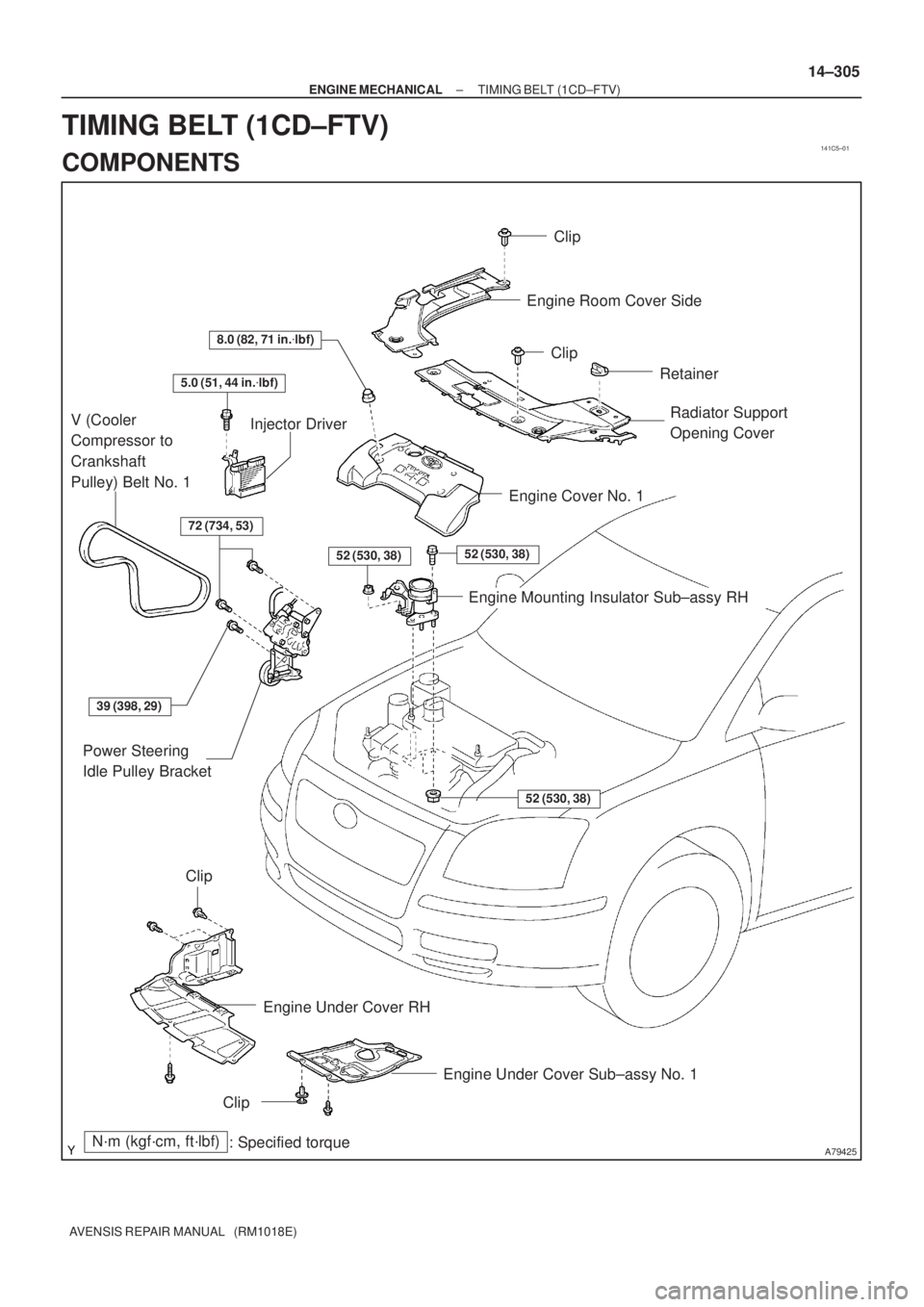
141C5±01
A79425N´m (kgf´cm, ft´lbf)
: Specified torque
8.0 (82, 71 in.�lbf)
72 (734, 53)
V (Cooler
Compressor to
Crankshaft
Pulley) Belt No. 1
Engine Cover No. 1Engine Room Cover Side
Radiator Support
Opening Cover
Power Steering
Idle Pulley Bracket
Engine Under Cover Sub±assy No. 1
Engine Under Cover RH
Injector Driver
52 (530, 38)
Engine Mounting Insulator Sub±assy RH
52 (530, 38)
52 (530, 38)
39 (398, 29)
Clip
Clip
Retainer
Clip
Clip
5.0 (51, 44 in.�lbf)
± ENGINE MECHANICALTIMING BELT (1CD±FTV)
14±305
AVENSIS REPAIR MANUAL (RM1018E)
TIMING BELT (1CD±FTV)
COMPONENTS

: Specified torque
52 (530, 38)52 (530, 38)
52 (530, 38)
Injector DriverEngine Mounting Insulator Sub±assy RH
Vacuum Reservoir Sub±assy
Union To Connector Tube Hose
Air")