Page 1448 of 5135

�� � � ��\b\bH42844
Airbag
Sensor
Assy
Center
Knee Squib
DK±
DK+
A
B
C
D
E
F
�� �
�����\f�����H42845
Airbag
Sensor
Assy
Center
Knee Squib
DLC3
CG TC DTC B1650/B1651/
B1652/B1653/49
C
D
E
F
±
DIAGNOSTICS SUPPLEMENTAL RESTRAINT SYSTEM
05±1377
AVENSIS REPAIR MANUAL (RM1018E)
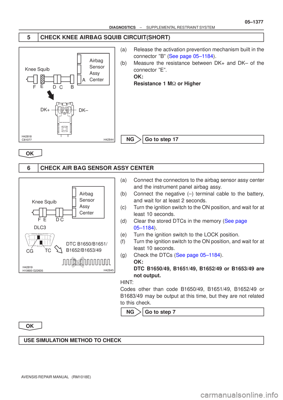
5CHECK KNEE AIRBAG SQUIB CIRCUIT(SHORT)
(a)Release the activation prevention mechanism built in the
connector ºBº (See page 05±1184).
(b)Measure the resistance between DK+ and DK± of the connector ºEº.
OK:
Resistance 1 M � or Higher
NGGo to step 17
OK
6CHECK AIR BAG SENSOR ASSY CENTER
(a)Connect the connectors to the airbag sensor assy center and the instrument panel airbag assy.
(b)Connect the negative (±) terminal cable to the battery, and wait for at least 2 seconds.
(c)Turn the ignition switch to the ON position, and wait for at
least 10 seconds.
(d)Clear the stored DTCs in the memory (See page 05±1184).
(e) Turn the ignition switch to the LOCK position.
(f) Turn the ignition switch to the ON position, and wait for at least 10 seconds.
(g)Check the DTCs (See page 05±1184). OK:
DTC B1650/49, B1651/49, B1652/49 or B1653/49 are
not output.
HINT:
Codes other than code B1650/49, B1651/49, B1652/49 or
B1683/49 may be output at this time, but they are not related
to this check.
NG Go to step 7
OK
USE SIMULATION METHOD TO CHECK
Page 1454 of 5135

������������H40584
P Squib
(2nd step)Airbag
Sensor
Assy
Center
P2+Instrument Panel Wire
A
B
C
D
±
DIAGNOSTICS SUPPLEMENTAL RESTRAINT SYSTEM
05±1371
AVENSIS REPAIR MANUAL (RM1018E)
DTC B1188/56 SHORT IN P SQUIB (2ND STEP) CIRCUIT
(TO B+)
CIRCUIT DESCRIPTION
The P squib (2nd step) circuit consists of the airbag sensor assy center \
and the instrument panel passenger
airbag assy.
This circuit actuates the SRS to deploy when the SRS deployment conditio\
ns are fulfilled.
DTC B1188/56 is recorded when a short to B+ is detected in the P squib (2nd s\
tep) circuit.
DTC No.DTC Detecting ConditionTrouble Area
B1188/56
�Short circuit in P squib (2nd step) wire harness (to B+)
� P squib (2nd step) malfunction
� Airbag sensor assy center malfunction�Instrument panel passenger airbag assy (P squib, 2nd step)
� Airbag sensor assy center
� Instrument panel wire
WIRING DIAGRAM
See page 05±1362.
INSPECTION PROCEDURE
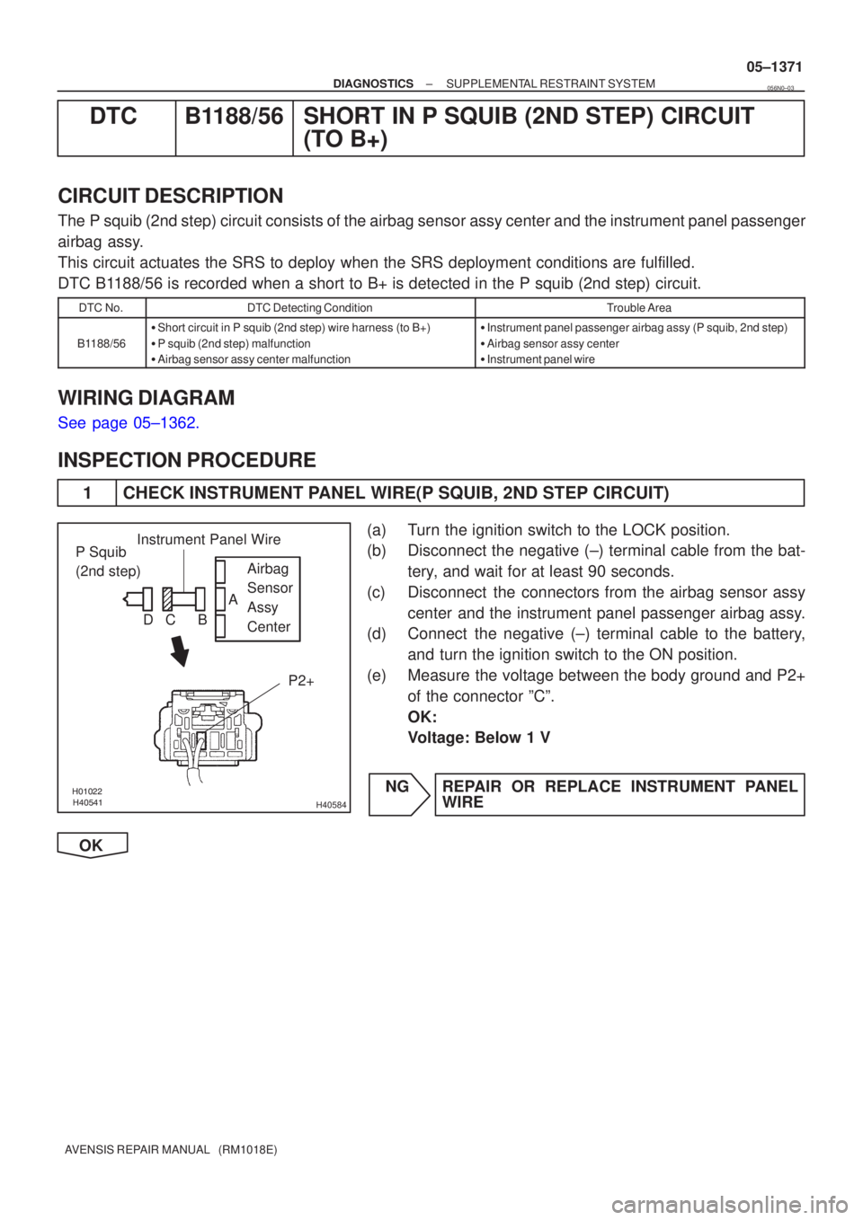
1 CHECK INSTRUMENT PANEL WIRE(P SQUIB, 2ND STEP CIRCUIT)
(a) Turn the ignition switch to the LOCK position.
(b) Disconnect the negative (±) terminal cable from the bat-
tery, and wait for at least 90 seconds.
(c) Disconnect the connectors from the airbag sensor assy center and the instrument panel passenger airbag assy.
(d) Connect the negative (±) terminal cable to the battery,
and turn the ignition switch to the ON position.
(e) Measure the voltage between the body ground and P2+ of the connector ºCº.
OK:
Voltage: Below 1 V
NG REPAIR OR REPLACE INSTRUMENT PANEL WIRE
OK
056N0±03
Page 1458 of 5135
05C3B±01
±
DIAGNOSTICS NAVIGATION SYSTEM
05±1435
AVENSIS REPAIR MANUAL (RM1018E)
NAVIGATION SYSTEM
HOW TO PROCEED WITH TROUBLESHOOTING
1Vehicle Brought to Workshop
2Customer Problem Analysis (See page 05±1437)
3 Problem Symptom Confirmation
Symptom does not occur (Go to step 4)
Symptom occurs (Go to step 5)
4Symptom Simulation (See page 01±32)
5DTC Check (See page 05±1438)
Normal code (Go to step 7)
Malfunction code (Go to step 6)
6DTC Chart (See page 05±1453)
Go to step 8
7Problem Symptoms Table (See page 05±1464)
8 Circuit Inspection and Part Inspection
9 Indemnification of Problem
Page 1480 of 5135
I35615
Battery FL MAIN
B±G (*1)B±G (*1)
4B 4A 4D
1 11
12 ALT
B±G (*1) B±G (*1)
Engine Room R/B No.4, Engine Room J/B No.4 1A1 DCC
1 Engine Room R/B No.1, Engine Room J/B No.1 B (*2) B (*2)
33
3 ALT
12W (*2)
ED11 B±L (*2)
B±W
IP1 IE454
(*6) (*3)B±W
6 6
1 2 RAD No.2Fuse Block
Engine Room R/B No.3 L±Y (*3)
L±Y (*4)
L±Y (*5)
INBR (*3)
W±B (*6)R9GND 7 DNDB DH
DH1 134
AM1 RAD No.1 Driver Side J/B
G±R I12 Ignition Switch
AM1 ACC
3 2GGR
J8 J8J20 J20 FF FF J/C
GR
R9 R9
ACC CE CB4
8 Center J/B
L±Y (*3) L±Y (*4) L±Y (*5)L±Y (*5) J24
J/C
EE
4
3+B Radio Receiver Assy
*1: Gasoline
*2: 1CD±FTV
*3: LHD*4: RHD, 1CD±FTV, w/o Multi±display
*5: RHD, Except *4
*6: RHD(*3) (*3)(*6) (*6)
1
2
± DIAGNOSTICSAUDIO SYSTEM
05±1413
AVENSIS REPAIR MANUAL (RM1018E)
POWER SOURCE CIRCUIT (RADIO RECEIVER ASSY)
WIRING DIAGRAM
05C4Z±01
Page 1481 of 5135
I35616
GND
ACC
+B
05±1414
±
DIAGNOSTICS AUDIO SYSTEM
AVENSIS REPAIR MANUAL (RM1018E)
INSPECTION PROCEDURE
1INSPECT RADIO RECEIVER ASSY(BU, ACC, GND)
(a)Remove the radio receiver assy.
(b)Check continuity between terminals at each condition, as shown in the chart.
Standard:
Tester connectionConditionSpecified condition
GND ± Body groundAlwaysContinuity
(c)Check the voltage between terminals at each condition,
as shown in the chart.
Standard:
Tester connectionConditionSpecified condition
+B ± GNDAlways10 to 14 V
ACC ± GNDIgnition SW ACC10 to 14 V
NGREPAIR OR REPLACE HARNESS OR CONNECTOR (See page 01±32)
OK
2 CHECK FOR PROBLEM SYMPTOMS TABLE
(a)Check problem symptoms table (See page 05±1412).
Suspected areas are clearedA
Suspected areas still existB
B PROCEED TO NEXT CIRCUIT INSPECTION SHOWN ON PROBLEM SYMPTOMS TABLE (See
page 05±1412 )
A
REPLACE RADIO RECEIVER ASSY
Page 1482 of 5135

0549M±11
05±1412
±
DIAGNOSTICS AUDIO SYSTEM
AVENSIS REPAIR MANUAL (RM1018E)
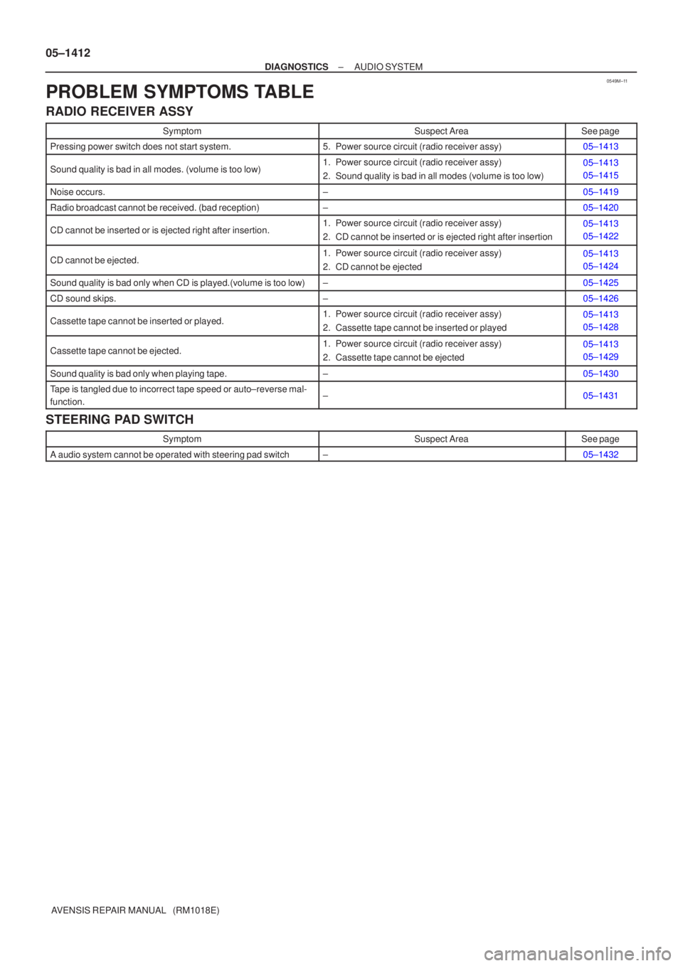
PROBLEM SYMPTOMS TABLE
RADIO RECEIVER ASSY
SymptomSuspect AreaSee page
Pressing power switch does not start system.5. Power source circuit (radio receiver assy)05±1413
Sound quality is bad in all modes. (volume is too low)1. Power source circuit (radio receiver assy)
2. Sound quality is bad in all modes (volume is too low)05±1413
05±1415
Noise occurs.±05±1419
Radio broadcast cannot be received. (bad reception)±05±1420
CD cannot be inserted or is ejected right after insertion.1. Power source circuit (radio receiver assy)
2. CD cannot be inserted or is ejected right after insertion05±1413
05±1422
CD cannot be ejected.1. Power source circuit (radio receiver assy)
2. CD cannot be ejected05±1413
05±1424
Sound quality is bad only when CD is played.(volume is too low)±05±1425
CD sound skips.±05±1426
Cassette tape cannot be inserted or played.1. Power source circuit (radio receiver assy)
2. Cassette tape cannot be inserted or played05±1413
05±1428
Cassette tape cannot be ejected.1. Power source circuit (radio receiver assy)
2. Cassette tape cannot be ejected05±1413
05±1429
Sound quality is bad only when playing tape.±05±1430
Tape is tangled due to incorrect tape speed or auto±reverse mal-
function.±05±1431
STEERING PAD SWITCH
SymptomSuspect AreaSee page
A audio system cannot be operated with steering pad switch±05±1432
Page 1489 of 5135
I34725
Multi±display
(CRT Display) Display
CTX±
CTX+
TX3+
TX3±
GTX+
GTX±M2
M1 M2
M1
M1
M110
5
12
24
5
18LG
V
G±Y
G
P
LG10
5Navigation ECU
Body ECU
(Combination Meter Assy)
Radio Receiver Assy3
4
9
10 C10
C10
R6
R6N4
N4TX±
TX+
TX± TX+
± DIAGNOSTICSNAVIGATION SYSTEM
05±1471
AVENSIS REPAIR MANUAL (RM1018E)
AVC±LAN CIRCUIT
WIRING DIAGRAM
INSPECTION PROCEDURE
1 INSPECT APPARATUS
(a) Choose the apparatus to be inspected.
ApparatusGo to step
Radio receiver assyA
Navigation ECUB
Body ECU (Combination Meter Assy)C
B Go to step 4
C Go to step 6
A
05C3K±01
Page 1493 of 5135
I34728
I13
Ignition SW
32
AM1 ACC
G±R34
11 DH
DH DNDB RAD No.1
AM1 GDriver Side J/BFF
(*3) (*4)J8 J20
FF
(*3) (*4)J8 J20J/CACC
B±G (*1)
B±G (*1)
B (*2) B±G (*1)
FL MAIN
Battery
*1: Gasoline
*2: 1CD±FTV
*3: LHD
*4: RHD1
4BALT
121
4D
3
3 ALT
12GR (*3)
HH
(*3) (*4)J9 J21
1
ED1 B±L (*2)
W (*2)
W (*2)
GND
1
A
J17
J/C
IP (*3)
IK (*4)N4
Navigation Controller Holder
GR
GR(*4)
W±B5
A Engine Room R/B J/B
Engine Room R/B No.3
W±B
± DIAGNOSTICSNAVIGATION SYSTEM
05±1469
AVENSIS REPAIR MANUAL (RM1018E)
POWER SOURCE CIRCUIT (NAVIGATION CONTROLLER HOLDER)
WIRING DIAGRAM
05C3J±01