Page 1528 of 5135

± DIAGNOSTICSCOMBINATION METER
05±1507
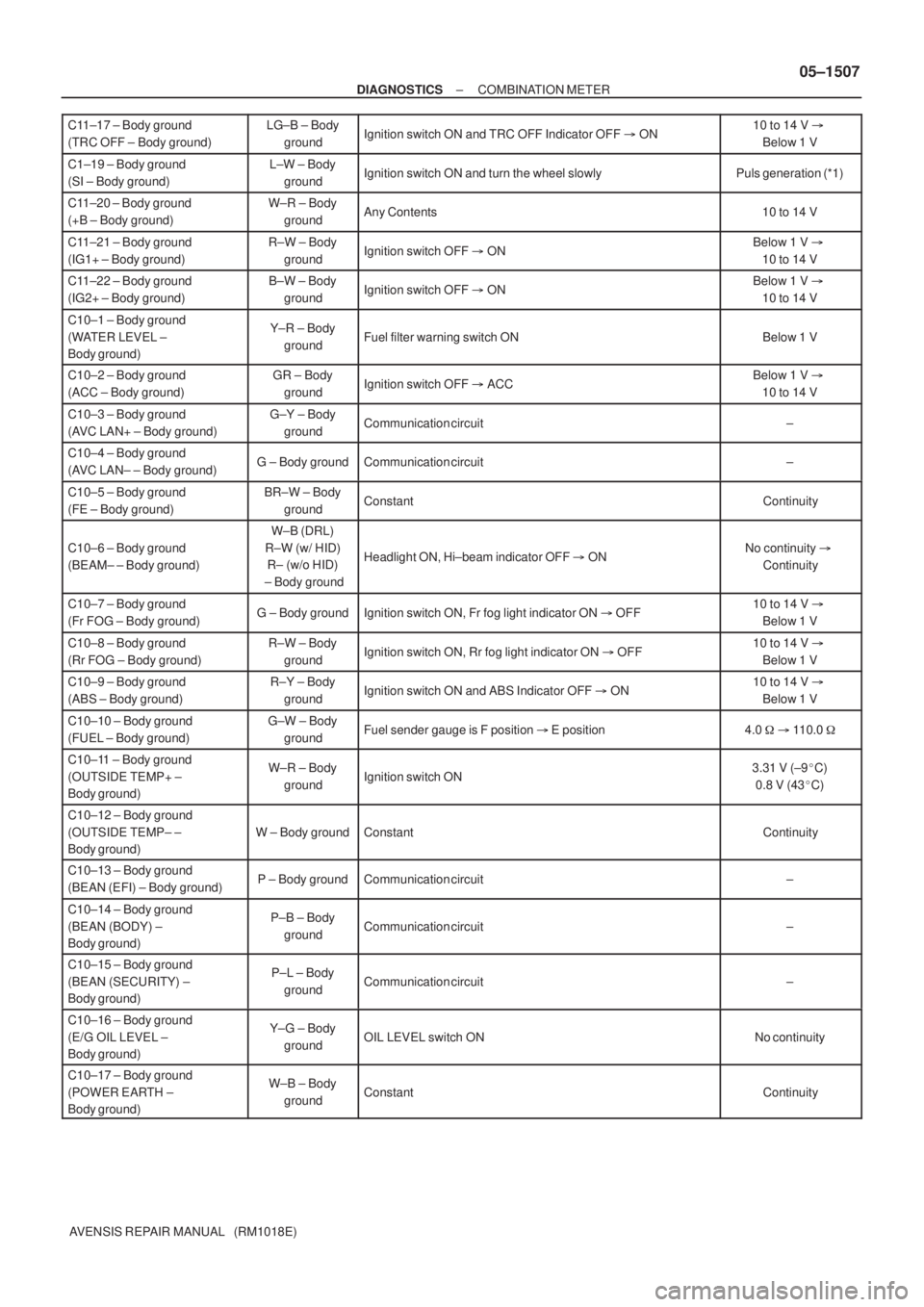
AVENSIS REPAIR MANUAL (RM1018E) C11±17 ± Body ground
(TRC OFF ± Body ground)
LG±B ± Body
groundIgnition switch ON and TRC OFF Indicator OFF � ON10 to 14 V �
Below 1 V
C1±19 ± Body ground
(SI ± Body ground)L±W ± Body
groundIgnition switch ON and turn the wheel slowlyPuls generation (*1)
C11±20 ± Body ground
(+B ± Body ground)W±R ± Body
groundAny Contents10 to 14 V
C11±21 ± Body ground
(IG1+ ± Body ground)R±W ± Body
groundIgnition switch OFF � ONBelow 1 V �
10 to 14 V
C11±22 ± Body ground
(IG2+ ± Body ground)B±W ± Body
groundIgnition switch OFF � ONBelow 1 V �
10 to 14 V
C10±1 ± Body ground
(WATER LEVEL ±
Body ground)Y±R ± Body
groundFuel filter warning switch ONBelow 1 V
C10±2 ± Body ground
(ACC ± Body ground)GR ± Body
groundIgnition switch OFF � ACCBelow 1 V �
10 to 14 V
C10±3 ± Body ground
(AVC LAN+ ± Body ground)G±Y ± Body
groundCommunication circuit±
C10±4 ± Body ground
(AVC LAN± ± Body ground)G ± Body groundCommunication circuit±
C10±5 ± Body ground
(FE ± Body ground)BR±W ± Body
groundConstantContinuity
C10±6 ± Body ground
(BEAM± ± Body ground)
W±B (DRL)
R±W (w/ HID)
R± (w/o HID)
± Body ground
Headlight ON, Hi±beam indicator OFF � ONNo continuity �
Continuity
C10±7 ± Body ground
(Fr FOG ± Body ground)G ± Body groundIgnition switch ON, Fr fog light indicator ON � OFF10 to 14 V �
Below 1 V
C10±8 ± Body ground
(Rr FOG ± Body ground)R±W ± Body
groundIgnition switch ON, Rr fog light indicator ON � OFF10 to 14 V �
Below 1 V
C10±9 ± Body ground
(ABS ± Body ground)R±Y ± Body
groundIgnition switch ON and ABS Indicator OFF � ON10 to 14 V �
Below 1 V
C10±10 ± Body ground
(FUEL ± Body ground)G±W ± Body
groundFuel sender gauge is F position � E position4.0 � � 110.0 �
C10±11 ± Body ground
(OUTSIDE TEMP+ ±
Body ground)W±R ± Body
groundIgnition switch ON3.31 V (±9�C)
0.8 V (43�C)
C10±12 ± Body ground
(OUTSIDE TEMP± ±
Body ground)
W ± Body groundConstantContinuity
C10±13 ± Body ground
(BEAN (EFI) ± Body ground)P ± Body groundCommunication circuit±
C10±14 ± Body ground
(BEAN (BODY) ±
Body ground)P±B ± Body
groundCommunication circuit±
C10±15 ± Body ground
(BEAN (SECURITY) ±
Body ground)P±L ± Body
groundCommunication circuit±
C10±16 ± Body ground
(E/G OIL LEVEL ±
Body ground)Y±G ± Body
groundOIL LEVEL switch ONNo continuity
C10±17 ± Body ground
(POWER EARTH ±
Body ground)W±B ± Body
groundConstantContinuity
Page 1534 of 5135
I34627
C11±21 (IG1+)
*3:
C11±10 (AUTO LEVELING)
C11±22 (IG2+)
C11±8 (AIR BAG)
C10±8 (Rr FOG)
C10±7 (Fr FOG) BUZZER
WATER LVL
CHECK E/G
VSC
SLIP
AUTO LVL
ABS
EMPS
BRAKE
A/B ACTIVE
CIRCUIT
E/G OIL LVL
FUEL
A/T OIL TEMP
CHG
ECT SNOW
D±SEAT BELT
Rr FOG
Fr FOG
TRC OFF
OIL/P
*1: GLOW
CRUISE AIR BAG
ABS ACTIVE
CIRCUIT
EMPS ACTIVE
CIRCUIT
BRAKE ACTIVE
CIRCUIT
C11±11 (OIL PRESS SW)
C11±4 (EBD) *3: C11±6 (EMPS)C10±9 (ABS) *1, 2: C11±15 (SLIP)*1, 2: C11±16 (VSC)
C11±2 (BRAKE LVL SW)
CPU
*1: 1CD±FTV, *2: 1AZ±FSE, 2AZ±FSE, *3: 1ZZ±FE, 3ZZ±FE
C11±9 (CHECK ENGINE)
*1, 2:
C11±17 (TRC OFF) 05±1504
± DIAGNOSTICSCOMBINATION METER
AVENSIS REPAIR MANUAL (RM1018E)
Page 1536 of 5135

056Q9±02
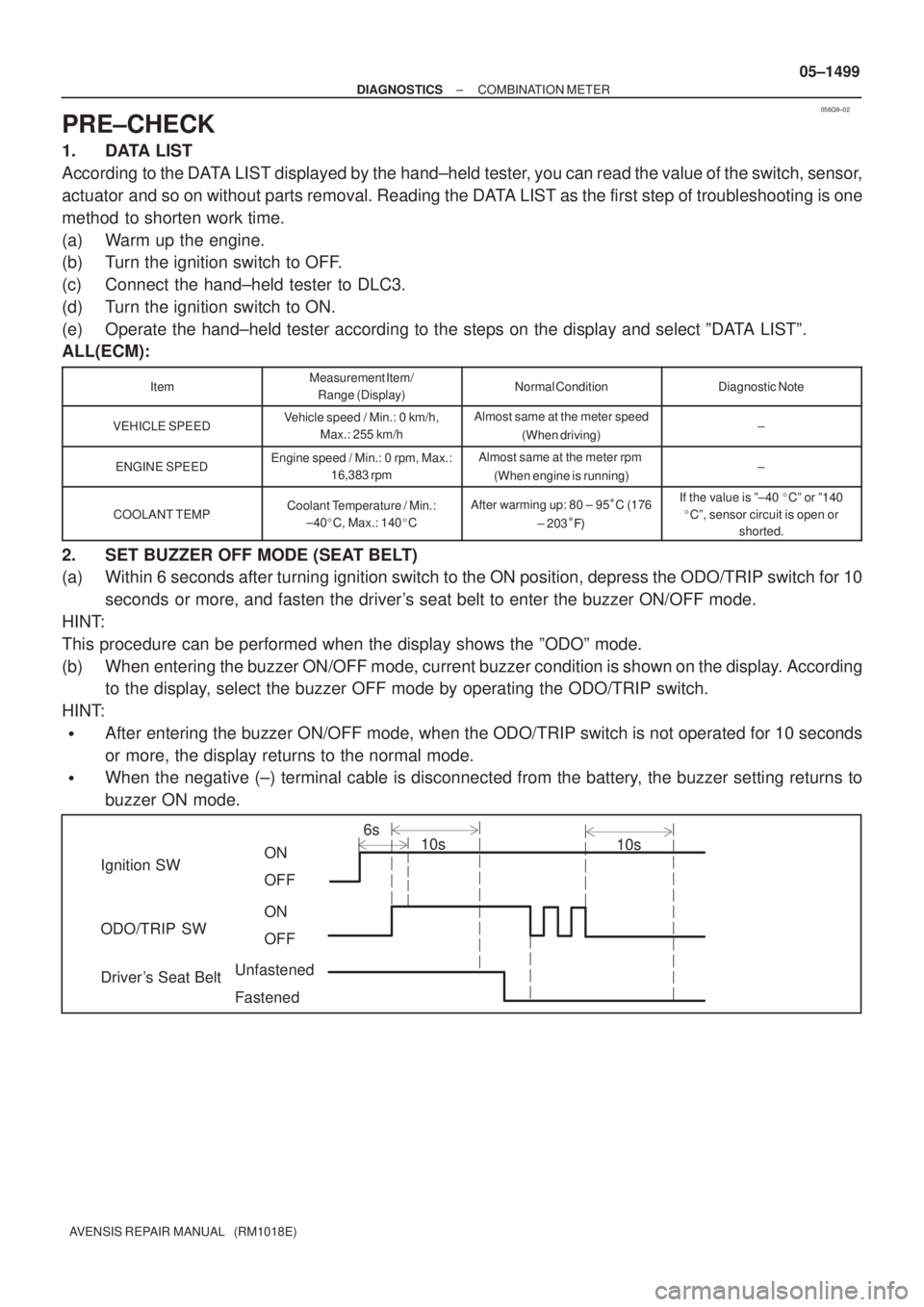
Ignition SW
ODO/TRIP SW
Driver's Seat BeltON
OFF
6s
10s10s
ON
OFF
Unfastened
Fastened
± DIAGNOSTICSCOMBINATION METER
05±1499
AVENSIS REPAIR MANUAL (RM1018E)
PRE±CHECK
1. DATA LIST
According to the DATA LIST displayed by the hand±held tester, you can read the value of the switch, sensor,
actuator and so on without parts removal. Reading the DATA LIST as the first step of troubleshooting is one
method to shorten work time.
(a) Warm up the engine.
(b) Turn the ignition switch to OFF.
(c) Connect the hand±held tester to DLC3.
(d) Turn the ignition switch to ON.
(e) Operate the hand±held tester according to the steps on the display and select ºDATA LISTº.
ALL(ECM):
ItemMeasurement Item/
Range (Display)Normal ConditionDiagnostic Note
VEHICLE SPEEDVehicle speed / Min.: 0 km/h,
Max.: 255 km/hAlmost same at the meter speed
(When driving)±
ENGINE SPEEDEngine speed / Min.: 0 rpm, Max.:
16,383 rpmAlmost same at the meter rpm
(When engine is running)±
COOLANT TEMPCoolant Temperature / Min.:
±40�C, Max.: 140�CAfter warming up: 80 ± 95�C (176
± 203���If the value is º±40 �Cº or º140
�Cº, sensor circuit is open or
shorted.
2. SET BUZZER OFF MODE (SEAT BELT)
(a) Within 6 seconds after turning ignition switch to the ON position, depress the ODO/TRIP switch for 10
seconds or more, and fasten the driver's seat belt to enter the buzzer ON/OFF mode.
HINT:
This procedure can be performed when the display shows the ºODOº mode.
(b) When entering the buzzer ON/OFF mode, current buzzer condition is shown on the display. According
to the display, select the buzzer OFF mode by operating the ODO/TRIP switch.
HINT:
�After entering the buzzer ON/OFF mode, when the ODO/TRIP switch is not operated for 10 seconds
or more, the display returns to the normal mode.
�When the negative (±) terminal cable is disconnected from the battery, the buzzer setting returns to
buzzer ON mode.
Page 1538 of 5135
056Q7±04
±
DIAGNOSTIC SCOMBIN ATION METER
05±1497
A VENSIS RE PAIR MANUAL (RM1018E)
COMBIN ATION METER
HOW T O PROCEED WITH TROUBLESHOOTING
1 Vehicl e Brought to Workshop
2 Customer Problem Analysis ( See page 05±1498)
3 Check multiplex communication system ( See page 05±1654)
(a) Check the DTC output.
DTC outputs (Proceed to ºBODY MULTIPLEX
COMMUNICATION SYSTEM)
DTC does not output (Go to step 4)
4Problem Symptom Confirmation ( See page 05±1509)
5 Circuit Inspection ( See page 05±1510 ± 05±1522 )
6 Repair or Replace
7 Confirmation Test
8 End
Page 1549 of 5135

±
DIAGNOSTICS NAVIGATION SYSTEM
05±1485
AVENSIS REPAIR MANUAL (RM1018E)
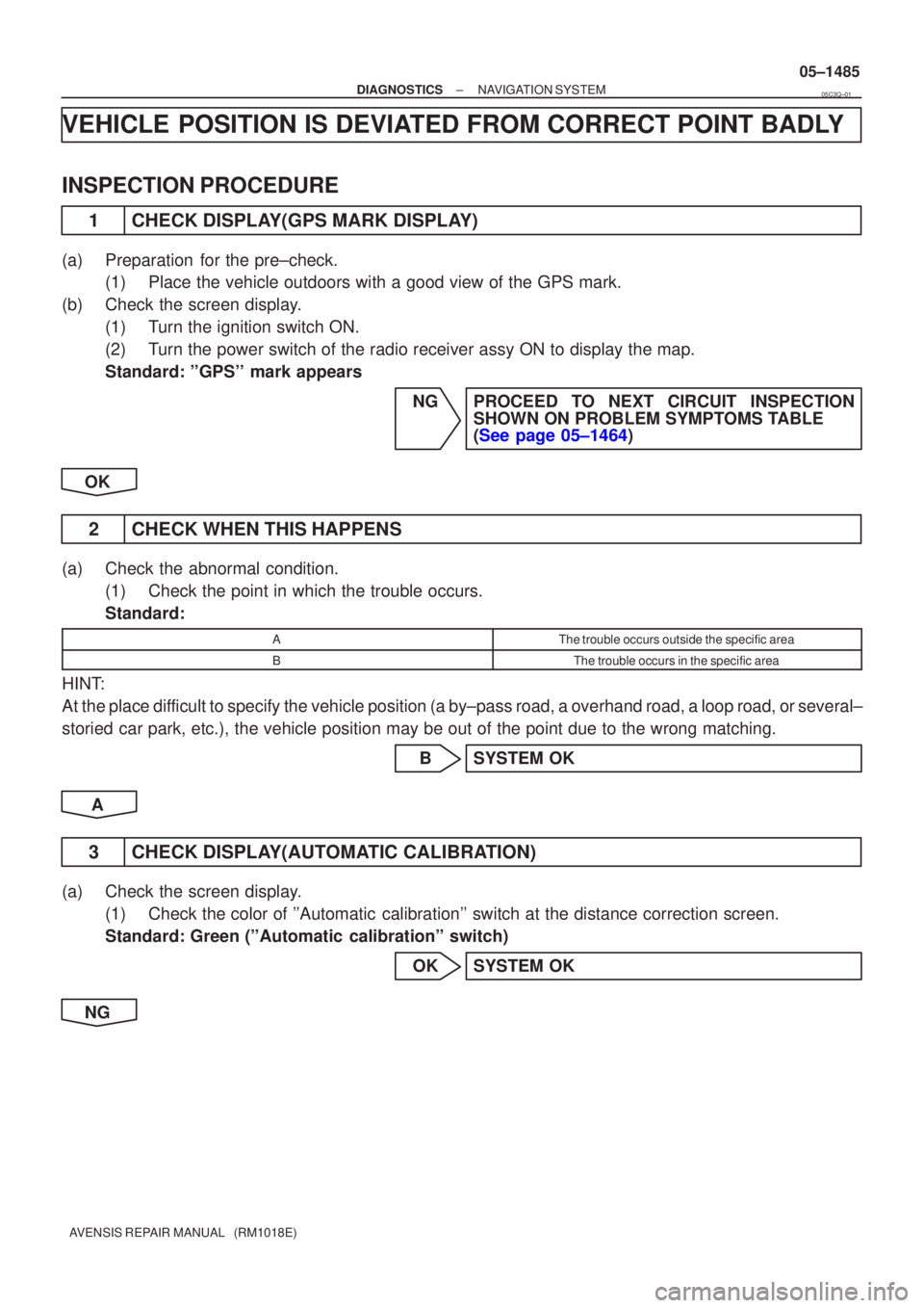
VEHICLE POSITION IS DEVIATED FROM CORRECT POINT BADLY
INSPECTION PROCEDURE
1CHECK DISPLAY(GPS MARK DISPLAY)
(a)Preparation for the pre±check.
(1)Place the vehicle outdoors with a good view of the GPS mark.
(b)Check the screen display. (1)Turn the ignition switch ON.
(2)Turn the power switch of the radio receiver assy ON to display the map.
Standard: ''GPS'' mark appears
NGPROCEED TO NEXT CIRCUIT INSPECTIONSHOWN ON PROBLEM SYMPTOMS TABLE
(See page 05±1464)
OK
2 CHECK WHEN THIS HAPPENS
(a) Check the abnormal condition. (1) Check the point in which the trouble occurs.
Standard:
AThe trouble occurs outside the specific area
BThe trouble occurs in the specific area
HINT:
At the place difficult to specify the vehicle position (a by±pass road, a overhand r\
oad, a loop road, or several±
storied car park, etc.), the vehicle position may be out of the point due to t\
he wrong matching.
B SYSTEM OK
A
3 CHECK DISPLAY(AUTOMATIC CALIBRATION)
(a) Check the screen display. (1) Check the color of ''Automatic calibration'' switch at the distance correction screen.
Standard: Green (''Automatic calibration'' switch)
OK SYSTEM OK
NG
05C3Q±01
Page 1579 of 5135
I34628
C11±5C11±20
C11±22
C11±21
± DIAGNOSTICSCOMBINATION METER
05±1521
AVENSIS REPAIR MANUAL (RM1018E)
INSPECTION PROCEDURE
1 INSPECT FUSE(GAUGE2, ECU±B)
(a) Check continuity in the GAUGE, DOME fuse.
NG REPLACE FUSE
OK
2 CHECK COMBINATION METER ASSY(POWER SOURCE AND GROUND CIRCUIT)
(a) Remove the combination meter assy.
(b) Check continuity.
(1) Check continuity between the terminal C11±5 of the
combination meter connector and the body ground.
Standard: Continuity.
(c) Check the voltage.
(1) Measure the voltage between the terminal C11±20
of the combination meter connector and the body
ground.
Standard voltage: 10 ± 14 V
(2) Turn the ignition switch to ON.
(3) Measure the voltage between the terminal C11±21,
22 of the combination meter connector and the
body ground.
Standard voltage: 10 ± 14 V
NG REPAIR OR REPLACE HARNESS OR
CONNECTOR
OK
CHECK AND REPLACE COMBINATION METER ASSY
Page 1582 of 5135

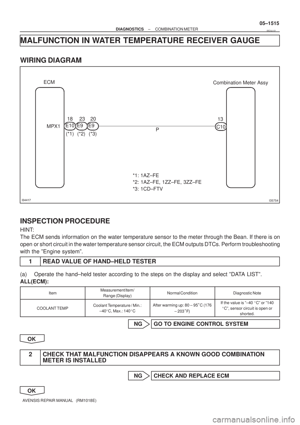
������I35754
Combination Meter Assy ECM
13
C10
P 20
E9 18
E1023
(*1) MPX1
(*2) (*3) E9
*1: 1AZ±FE
*2: 1AZ±FE, 1ZZ±FE, 3ZZ±FE
*3: 1CD±FTV
± DIAGNOSTICSCOMBINATION METER
05±1515
AVENSIS REPAIR MANUAL (RM1018E)
MALFUNCTION IN WATER TEMPERATURE RECEIVER GAUGE
WIRING DIAGRAM
INSPECTION PROCEDURE
HINT:
The ECM sends information on the water temperature sensor to the meter through the Bean. If there is on
open or short circuit in the water temperature sensor circuit, the ECM outputs DTCs. Perform troubleshooting
with the ºEngine systemº.
1 READ VALUE OF HAND±HELD TESTER
(a) Operate the hand±held tester according to the steps on the display and select ºDATA LISTº.
ALL(ECM):
ItemMeasurement Item/
Range (Display)Normal ConditionDiagnostic Note
COOLANT TEMPCoolant Temperature / Min.:
±40�C, Max.: 140�CAfter warming up: 80 ± 95�C (176
± 203���If the value is º±40 �Cº or º140
�Cº, sensor circuit is open or
shorted.
NG GO TO ENGINE CONTROL SYSTEM
OK
2 CHECK THAT MALFUNCTION DISAPPEARS A KNOWN GOOD COMBINATION
METER IS INSTALLED
NG CHECK AND REPLACE ECM
OK
05C4J±01
Page 1589 of 5135
B66771
KSW
W±B8 U1
Unlock Warning Switch Assy
W±B
IP5
+B GROUND 1
W±R W±B
2
1Instrument Panel J/B Assy
PRG
RDA 16
2PRG
RDA D6
Door Control Receiver
7Integration
Relay
IC2 I14 3 G±Y
L±W 16
7
To
Battery
DA Y
IO*
1
6 8
Center
J/BIC2 G±Y
L±W
CA CD
AJ16
J/C LHD Models
19 I14
A W±B
IL*
2*1: Gasoline Engine
*2: 1CD±FTV
± DIAGNOSTICSWIRELESS DOOR LOCK CONTROL SYSTEM
05±1575
AVENSIS REPAIR MANUAL (RM1018E)
ONLY WIRELESS CONTROL FUNCTION DOES NOT OPERATE
(PREPARE NEW OR NORMAL TRANSMITTER OF THE SAME
TYPE VEHICLE)
CIRCUIT DESCRIPTION
The door control receiver receives a signal from the transmitter and sends this signal to the integration relay.
Then, the integration relay controls door operation by sending a door LOCK/UNLOCK signal and a luggage
door (back door) unlock signal to each door lock motor.
WIRING DIAGRAM
05BNB±01