Page 1431 of 5135

6. MAINTENANCE
Tape Player / Head Cleaning:
(a) Raise the slot cover with your fi")
N17398
Example :
HeadCapstan
Pinch Roller
BE4331
± DIAGNOSTICSAUDIO SYSTEM
05±1395
AVENSIS REPAIR MANUAL (RM1018E)
6. MAINTENANCE
Tape Player / Head Cleaning:
(a) Raise the slot cover with your finger.
Using a pencil or similar object, push in the guide.
(b) Using a cleaning pen or cotton applicator soaked in clean-
er, clean the head surface, pinch rollers and capstans.
7. MAINTENANCE
CD Player / Disc Cleaning:
If the disc gets dirty, clean the disc by wiping the surface from
the center to outside in the radial directions with a soft cloth.
NOTICE:
Do not use a conventional record cleaner or anti±static pre-
servative.
8. COMMUNICATION SYSTEM
(a) Components in the audio system communicate each other though AVC±LAN. (Radio receiver func-
tion)
(b) The master component of AVC±LAN is the radio receiver assy with a resistance (60 ± 80 �), which
is necessary for communication.
(c) When short circuit or open circuit occurs in the AVC±LAN circuit, the audio system does not operate
normally due to the communication cutoff.
9. DIAGNOSIS FUNCTION
(a) The audio system has diagnosis function (The diagnosis result is displayed on the LCD of the radio
receiver assy). (Radio receiver function)
(b) The component code (physical address), or three±digit number (in hexadecimal) is set for each com-
ponent comprising AVC±LAN.
(c) The logical address, or two±digit number (in hexadecimal) is set for each function and component unit
in each component.
Page 1432 of 5135
H43588
Driver Side J/BAirbag Sensor Assy Center
D5 DLC3
TCW−
L
J21D
J/C
(*2) TC
(*2)
W− L
(*1) J20
B
(*2)
J8
B
(*1) W−
L
DB17
DD8
J8 B
(*1) A27
19
13 W−
L
1AZ−
FSE, 1CD− FTV Engine:
CG TC TC
TC
TC
W−
L
W− L
W− L
W−
L
W−B
W−
B
W−
B
W− B
(*1)
(*2) J9 J21
DD
(*2)(*1)
DL DC
15
3
E9
S1
S2
20
17
25
(*2)
A
J16
J/C
A
(*1)
IO IP
(*3)
M1
16
4
CA
CB 3
6
(*6)
(*4, *5)
Skid Control ECU with Actuator Skid Control ECU with Actuator ECM
Multi− Display
*1: LHD *2: RHD
*3: w/ Navigation System (Map Type) *4:
1AZ− FSE
*5: 1CD− FTV (w/ VSC)
*6: 1CD− FTV (w/ ABS)
Center J/B
−
DIAGNOSTICS SUPPLEMENTAL RESTRAINT SYSTEM
05−1391
TC TERMINAL CIRCUIT
CIRCUIT DESCRIPTION
DTC output mode is set by connecting terminals TC and CG of the DLC3.
The DTCs are displayed by blinking the SRS warning light.
WIRING DIAGRAM
05C65 −01
Page 1437 of 5135

SRS WARNING LIGHT CIRCUIT MALFUNCTION (DOES NOT LIGHT
UP, WHEN IGNITION SWITCH IS TURNED TO ON)
CIRCUIT DESCRIPTI")
± DIAGNOSTICSSUPPLEMENTAL RESTRAINT SYSTEM
05±1389
AVENSIS REPAIR MANUAL (RM1018E)
SRS WARNING LIGHT CIRCUIT MALFUNCTION (DOES NOT LIGHT
UP, WHEN IGNITION SWITCH IS TURNED TO ON)
CIRCUIT DESCRIPTION
The SRS warning light is located on the combination meter assy.
When the SRS is normal, the SRS warning light comes on for approx. 6 seconds after the ignition switch
is turned from the LOCK position to the ON position, and then it turns off automatically.
If there is a malfunction in the SRS, the SRS warning light comes on to inform a trouble to the driver.
When between terminal TC and terminal CG of the DLC3 are connected, the DTC is displayed by blinking
the SRS warning light.
WIRING DIAGRAM
See page .
INSPECTION PROCEDURE
1 CHECK SOURCE VOLTAGE
(a) Measure the voltage of the battery.
OK:
Voltage: 10 to 14 V
NG HARNESS BETWEEN BATTERY AND AIRBAG
SENSOR ASSY CENTER, AND CHARGING
SYSTEM
OK
2 CHECK AIR BAG SENSOR ASSY CENTER
(a) Turn the ignition switch to the LOCK position.
(b) Disconnect the negative (±) terminal cable from the battery, and wait for at least 90 seconds.
(c) Disconnect the connectors from the airbag sensor assy center.
(d) Connect the negative (±) terminal cable to the battery, and turn the ignition switch to the ON position.
(e) Check that the SRS warning light operation.
OK:
The SRS warning light does not come on.
NG REPLACE AIR BAG SENSOR ASSY CENTER
OK
056N4±03
Page 1439 of 5135
H42518
Combination Meter Assy
Driver Side J/BAirbag Sensor Assy Center
*1: LHD
*2: RHD
*3: Gasoline
*4: 1CD±FTV SRS8
C11B±Y
J16
J/C(*2)
IL 17
C1012
DA6
DDB±Y3
A27
LA
W±B
J15
J/C W±B
(*1)
A
AW±B
W±B
(*1, *4)(*1, *3)(*2) W±B
A
A J17
J/C
A
IO
IK 05±1386
± DIAGNOSTICSSUPPLEMENTAL RESTRAINT SYSTEM
AVENSIS REPAIR MANUAL (RM1018E)
SRS WARNING LIGHT CIRCUIT MALFUNCTION (ALWAYS LIGHT
UP, WHEN IGNITION SWITCH IS ACC OR LOCK POSITION)
CIRCUIT DESCRIPTION
The SRS warning light is located on the combination meter assy.
When the SRS is normal, the SRS warning light comes on for approx. 6 seconds after the ignition switch
is turned from the LOCK position to the ON position, and then it turns off automatically.
If there is a malfunction in the SRS, the SRS warning light comes on to inform a trouble to the driver.
When between terminal TC and terminal CG of the DLC3 are connected, the DTC is displayed by blinking
the SRS warning light.
WIRING DIAGRAM
05C64±01
Page 1442 of 5135

H42517
Airbag Sensor Assy Center
A275
E1
E2 27IG2 2
1
Battery28 4IGN Driver Side J/B
IG2
AM2 I13
Ignition SW
B
4 3 6
Engine Room R/B No.1, Engine Room J/B No.1 AM2B±R
DD
W±BB±W
A27
A27 DD DH5
DAW±B 1 11
B±R1
1
1A
2
1 IE4 IP1
(*3)
(*4)(*1) B±G
Engine Room R/B No.3
Engine Room J/B No.43
DD 4B4A
3 9(*1) B±G (*2)
(*1) B±GB
(*2)
Driver Side J/B
IJ FL MAIN
W±B
*1: Gasoline
*2: 1CD±FTV*3: LHD
*4: RHD B±R
± DIAGNOSTICSSUPPLEMENTAL RESTRAINT SYSTEM
05±1383
AVENSIS REPAIR MANUAL (RM1018E)
SOURCE VOLTAGE DROP
CIRCUIT DESCRIPTION
The SRS is equipped with a voltage±increase circuit (DC±DC converter) in the airbag sensor assy center
in case the source voltage drops.
When the battery voltage drops, the voltage±increase circuit (DC±DC converter) functions to increase the
voltage of the SRS to normal voltage.
A malfunction in this circuit is displayed by different form from the other code. The source voltage drop is
indicated when the SRS warning light comes on without showing any DTCs.
Malfunction in this circuit is not recorded in the airbag sensor assy center. The SRS warning light automatical-
ly goes off when the source voltage returns to normal.
DTC No.Diagnosis
(Normal)Source voltage drop
WIRING DIAGRAM
056N1±04
Page 1445 of 5135

DTC B")
H42516
K3
Knee Airbag SquibAirbag Sensor Assy Center
Y±R
IN1
2
1A2811
DK±
1 2
A2812
IN1 Y±BY±R
Y±B
DK+ 05±1374
± DIAGNOSTICSSUPPLEMENTAL RESTRAINT SYSTEM
AVENSIS REPAIR MANUAL (RM1018E)
DTC B1650/49 SHORT IN KNEE SQUIB CIRCUIT
DTC B1651/49 OPEN IN KNEE SQUIB CIRCUIT
DTC B1652/49 SHORT IN KNEE SQUIB CIRCUIT (TO
GROUND)
DTC B1653/49 SHORT IN KNEE SQUIB CIRCUIT (TO B+)
CIRCUIT DESCRIPTION
The knee squib circuit consists of the airbag sensor assy center and the instrument panel airbag assy.
This circuit actuates the SRS to deploy when the SRS deployment conditions are fulfilled.
When the malfunction is detected in the knee squib circuit under the following conditions, these codes are
recorded.
�DTC B1650/49 is for short circuit
�DTC B1651/49 is for open circuit
�DTC B1652/49 is for short to ground
�DTC B1653/49 is for short to B+
DTC No.DTC Detection ConditionTrouble Area
B1650/49
B1651/49
B1652/49
B1653/49
�Short circuit between DK+ wire harness and DK± wire har-
ness of squib
�Open circuit in DK+ wire harness or DK± wire harness of
squib
�Short circuit in knee squib wire harness (to ground)
�Short circuit in knee squib wire harness (to B+)
�Knee squib malfunction
�Airbag sensor assy center
�Instrument panel airbag assy (Knee squib)
�Instrument panel wire
�Floor wire No.2
�Airbag sensor assy center
WIRING DIAGRAM
05C63±01
Page 1446 of 5135
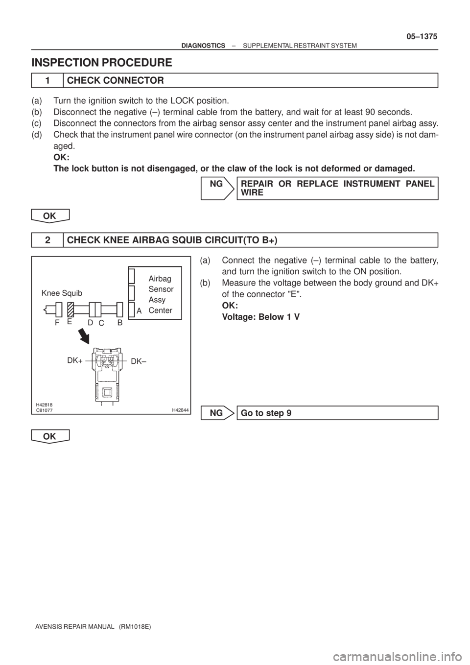
������������H42844
Airbag
Sensor
Assy
Center Knee Squib
DK± DK+
A
B
C D E
F
± DIAGNOSTICSSUPPLEMENTAL RESTRAINT SYSTEM
05±1375
AVENSIS REPAIR MANUAL (RM1018E)
INSPECTION PROCEDURE
1 CHECK CONNECTOR
(a) Turn the ignition switch to the LOCK position.
(b) Disconnect the negative (±) terminal cable from the battery, and wait for at least 90 seconds.
(c) Disconnect the connectors from the airbag sensor assy center and the instrument panel airbag assy.
(d) Check that the instrument panel wire connector (on the instrument panel airbag assy side) is not dam-
aged.
OK:
The lock button is not disengaged, or the claw of the lock is not deformed or damaged.
NG REPAIR OR REPLACE INSTRUMENT PANEL
WIRE
OK
2 CHECK KNEE AIRBAG SQUIB CIRCUIT(TO B+)
(a) Connect the negative (±) terminal cable to the battery,
and turn the ignition switch to the ON position.
(b) Measure the voltage between the body ground and DK+
of the connector ºEº.
OK:
Voltage: Below 1 V
NG Go to step 9
OK
Page 1447 of 5135
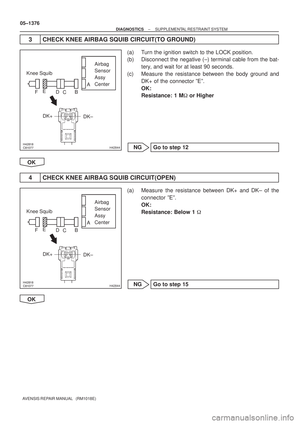
������������H42844
Airbag
Sensor
Assy
Center Knee Squib
DK± DK+
A
B
C D E
F
������������H42844
Airbag
Sensor
Assy
Center Knee Squib
DK± DK+
A
B
C D E
F
05±1376
± DIAGNOSTICSSUPPLEMENTAL RESTRAINT SYSTEM
AVENSIS REPAIR MANUAL (RM1018E)
3 CHECK KNEE AIRBAG SQUIB CIRCUIT(TO GROUND)
(a) Turn the ignition switch to the LOCK position.
(b) Disconnect the negative (±) terminal cable from the bat-
tery, and wait for at least 90 seconds.
(c) Measure the resistance between the body ground and
DK+ of the connector ºEº.
OK:
Resistance: 1 M� or Higher
NG Go to step 12
OK
4 CHECK KNEE AIRBAG SQUIB CIRCUIT(OPEN)
(a) Measure the resistance between DK+ and DK± of the
connector ºEº.
OK:
Resistance: Below 1 �
NG Go to step 15
OK
 TC
(*2)
W− L
(*1) J20
B
(*2)
J8
B
(*1) W−
L
DB17
DD8
J8 B
(*1) A27
19
13 W−
L
1AZ−
FSE, 1CD− FTV Engine:
CG TC")

IL 17
C1012
DA6
DDB±Y3
A27
LA
W±B
J15
J/C W±B
(*1)
A
AW±B")