Page 1403 of 5135

DTC B11")
�����
\b�����
����
����
H41469
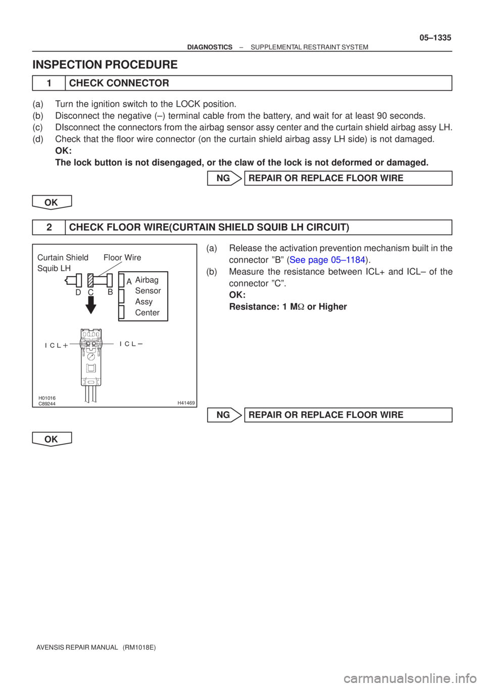
Curtain Shield
Squib LH
Airbag
Sensor
Assy
Center
Floor Wire
A
B
C
D
±
DIAGNOSTICS SUPPLEMENTAL RESTRAINT SYSTEM
05±1337
AVENSIS REPAIR MANUAL (RM1018E)
DTC B1166/88 OPEN IN CURTAIN SHIELD SQUIB (LH)
CIRCUIT
CIRCUIT DESCRIPTION
The curtain shield squib LH circuit consists of the airbag sensor assy cent\
er and the curtain shield airbag
assy LH.
This circuit actuates the SRS to deploy when the SRS deployment conditio\
ns are fulfilled.
DTC B1166/88 is recorded when an open circuit is detected in the curtain shiel\
d squib LH circuit.
DTC No.DTC Detecting ConditionTrouble Area
B1166/88
�Open circuit in ICL+ wire harness or ICL± wire harness of
curtain shield squib LH
� Curtain shield squib LH malfunction
� Airbag sensor assy center malfunction�Curtain shield airbag assy LH (Curtain shield squib LH)
� Airbag sensor assy center
� Floor wire
HINT:
DTC B1166/88 is indicated only for the vehicle equipped with the curtain shiel\
d airbag.
WIRING DIAGRAM
See page 05±1184.
INSPECTION PROCEDURE
1 CHECK FLOOR WIRE(CURTAIN SHIELD SQUIB LH CIRCUIT)
(a) Turn the ignition switch to the LOCK position.
(b) Disconnect the negative (±) terminal cable from the bat-
tery, and wait for at least 90 seconds.
(c) Disconnect the connectors from the airbag sensor assy center and the curtain shield airbag assy LH.
(d) Measure the resistance between ICL+ and ICL± of the connector ºCº.
OK:
Resistance: Below 1 �
NG REPAIR OR REPLACE FLOOR WIRE
OK
056MO±03
Page 1406 of 5135

(*1)
*1: w/ Curtain Shield Airbag 05±1334
± DIAGNOSTICSSUPPLEMENTAL RESTRAINT SYSTEM
AVENSIS REPAIR")
H01454
C17
Curtain Shield Squib LHAirbag Sensor Assy Center
1
2Y±V
Y±RA26
A269
10ICL+
ICL± (*1)
(*1)
*1: w/ Curtain Shield Airbag 05±1334
± DIAGNOSTICSSUPPLEMENTAL RESTRAINT SYSTEM
AVENSIS REPAIR MANUAL (RM1018E)
DTC B1165/87 SHORT IN CURTAIN SHIELD SQUIB (LH)
CIRCUIT
CIRCUIT DESCRIPTION
The curtain shield squib LH circuit consists of the airbag sensor assy center and the curtain shield airbag
assy LH.
This circuit actuates the SRS to deploy when the SRS deployment conditions are fulfilled.
DTC B1165/87 is recorded when a short circuit is detected in the curtain shield squib LH circuit.
DTC No.DTC Detecting ConditionTrouble Area
B1165/87
�Short circuit between ICL+ wire harness and ICL± wire har-
ness of curtain shield squib LH
�Curtain shield squib LH malfunction
�Airbag sensor assy center malfunction�Curtain shield airbag assy LH (Curtain shield squib LH)
�Airbag sensor assy center
�Floor wire
HINT:
DTC B1165/87 is indicated only for the vehicle equipped with the curtain shield airbag.
WIRING DIAGRAM
056MN±03
Page 1407 of 5135
�����
\b�����
����
����
H41469
Curtain Shield
Squib LH
Airbag
Sensor
Assy
Center
Floor Wire
A
B
C
D
±
DIAGNOSTICS SUPPLEMENTAL RESTRAINT SYSTEM
05±1335
AVENSIS REPAIR MANUAL (RM1018E)
INSPECTION PROCEDURE
1CHECK CONNECTOR
(a)Turn the ignition switch to the LOCK position.
(b)Disconnect the negative (±) terminal cable from the battery, and wait for at least 90 seconds.
(c)DIsconnect the connectors from the airbag sensor assy center and the curtain shield airbag assy LH.
(d)Check that the floor wire connector (on the curtain shield airbag assy LH si\
de) is not damaged.
OK:
The lock button is not disengaged, or the claw of the lock is not deform\
ed or damaged.
NGREPAIR OR REPLACE FLOOR WIRE
OK
2CHECK FLOOR WIRE(CURTAIN SHIELD SQUIB LH CIRCUIT)
(a)Release the activation prevention mechanism built in the connector ºBº (See page 05±1184).
(b) Measure the resistance between ICL+ and ICL± of the connector ºCº.
OK:
Resistance: 1 M � or Higher
NG REPAIR OR REPLACE FLOOR WIRE
OK
Page 1409 of 5135

DTC")
\b�����
������
����
����
H41465
Curtain Shield
Squib RH Airbag
Sensor
Assy
Center
Floor Wire No.2
A
B
C
D
±
DIAGNOSTICS SUPPLEMENTAL RESTRAINT SYSTEM
05±1331
AVENSIS REPAIR MANUAL (RM1018E)
DTC B1163/82 SHORT IN CURTAIN SHIELD SQUIB (RH)
CIRCUIT (TO B+)
CIRCUIT DESCRIPTION
The curtain shield squib RH circuit consists of the airbag sensor assy cent\
er and the curtain shield airbag
assy RH.
This circuit actuates the SRS to deploy when the SRS deployment conditio\
ns are fulfilled.
DTC B1163/82 is recorded when a short to B+ is detected in the curtain shield \
squib RH circuit.
DTC No.DTC Detecting ConditionTrouble Area
B1163/82
�Short circuit in curtain shield squib RH wire harness (to B+)
� Curtain shield squib RH malfunction
� Airbag sensor assy center malfunction�Curtain shield airbag assy RH (Curtain shield squib RH)
� Airbag sensor assy center
� Floor wire No.2
HINT:
DTC B1163/82 is indicated only for the vehicle equipped with the curtain shiel\
d airbag.
WIRING DIAGRAM
See page 05±1322.
INSPECTION PROCEDURE
1 CHECK FLOOR WIRE NO.2(CURTAIN SHIELD SQUIB RH CIRCUIT)
(a) Turn the ignition switch to the LOCK position.
(b) Disconnect the negative (±) terminal cable from the bat-
tery, and wait for at least 90 seconds.
(c) Disconnect the connectors from the airbag sensor assy center and the curtain shield airbag assy RH.
(d) Connect the negative (±) terminal cable to the battery, and turn the ignition switch to the ON position.
(e) Measure the voltage between the body ground and ICR+ of the connector ºCº.
OK:
Voltage: Below 1 V
NG REPAIR OR REPLACE FLOOR WIRE NO.2
OK
054MG±05
Page 1412 of 5135

DTC")
\b�����
������
����
����
H41465
Curtain Shield
Squib RH Airbag
Sensor
Assy
Center
Floor Wire No.2
A
B
C
D
05±1328
±
DIAGNOSTICS SUPPLEMENTAL RESTRAINT SYSTEM
AVENSIS REPAIR MANUAL (RM1018E)
DTC B1162/81 SHORT IN CURTAIN SHIELD SQUIB (RH) CIRCUIT (TO GROUND)
CIRCUIT DESCRIPTION
The curtain shield squib RH circuit consists of the airbag sensor assy cent\
er and the curtain shield airbag
assy RH.
This circuit actuates the SRS to deploy when the SRS deployment conditio\
ns are fulfilled.
DTC B1162/81 is recorded when a short to ground is detected in the curtain shi\
eld squib RH circuit.
DTC No.DTC Detecting ConditionTrouble Area
B1162/81
�Short circuit in curtain shield squib RH wire harness (to
ground)
� Curtain shield squib RH malfunction
� Airbag sensor assy malfunction�Curtain shield airbag assy RH (Curtain shield squib RH)
� Airbag sensor assy center
� Floor wire No.2
HINT:
DTC B1162/81 is indicated only for the vehicle equipped with the curtain shiel\
d airbag.
WIRING DIAGRAM
See page 05±1322.
INSPECTION PROCEDURE
1 CHECK FLOOR WIRE NO.2(CURTAIN SHIELD SQUIB RH CIRCUIT)
(a) Turn the ignition switch to the LOCK position.
(b) Disconnect the negative (±) terminal cable from the bat-
tery, and wait for at least 90 seconds.
(c) Disconnect the connectors from the airbag sensor assy center and the curtain shield airbag assy RH.
(d) Measure the resistance between the body ground and ICR+ of the connector ºCº.
OK:
Resistance: 1 M � or Higher
NG REPAIR OR REPLACE FLOOR WIRE NO.2
OK
054MF±05
Page 1421 of 5135

(d) Service Check Mode Result Display (for checking the cur-
rent and the past system conditions).
(1) Press the ºSEEK TRACKº sw")
05±1400
± DIAGNOSTICSAUDIO SYSTEM
AVENSIS REPAIR MANUAL (RM1018E)
(d) Service Check Mode Result Display (for checking the cur-
rent and the past system conditions).
(1) Press the ºSEEK TRACKº switch to see the check
result of each device.
(2) Check Result Display.
DisplayOriginal LanguageMeaningAction to be taken
goodGood (normal)No DTCs are detected in both ºSystem Check Modeº and
ºDiagnosis Memory Modeº.±
NCONNo connection
The system recognized the component when it was regis-
tered, but the component gives no response to the ºDiagno-
sis Mode ON Requestº.
Check the power source cir-
cuit and the communication
circuit of the device indi-
cated by the device code
(physical address).
ECHNExchangeOne or more DTC for ºExchangeº is detected in either ºSys-
tem Check Modeº or ºDiagnosis Memory Modeº.
Go to the detail information
mode to check the trouble
area referring to the DTC
list.
CHECCheck
When no DTCs are detected for ºExchangeº, one or more
DTC for ºCheck is detected in either ºSystem Check Modeº
or ºDiagnosis Memory Modeº.Go to the detail information
mode to check the trouble
area referring to the DTC
list.
I34696
The illustration shows the case that the system has 2 devices with codes 190 and 360, and the device (code
360) requires a check.
The check result is displayed in ascending order of device code. The device code is displayed first, and then
the check result.P±±±indicates physical address
190±±±physical address
good±±±ºThe component is normalº.
P±±±indicates physical address
360±±±physical address
CHEC±±±ºCheck neededº.
: SEEK TRACK UP
: SEEK TRACK DOWN
Page 1422 of 5135
± DIAGNOSTICSAUDIO SYSTEM
05±1401
AVENSIS REPAIR MANUAL (RM1018E) DisplayAction to be taken Meaning Original Language
OLDOld versionOld DTC application is identified and DTC is detected in ei-
ther ºSystem Check Modeº or ºDiagnosis Memory Modeº.±
NRESNo response
The device gives no response to any one of ºSystem Check
Mode ON Requestº, ºSystem Check Result Requestº and
ºDiagnosis Memory Requestº.
Check the power source cir-
cuit and the communication
circuit of the device indi-
cated by the device code
(physical code).
(3) To perform the Service Check again, press the pre-
set switch º1º.
(e) Detailed information Mode (when displaying the troubled
device's DTC)
(1) With ºCHECº or ºECHNº being displayed, press the
preset switch º2º to go to the detailed information
mode.
(2) Press the ºSEEK TRACKº switch to display ºSystem
Check Result (SYS)º and ºDiagnosis Memory Re-
sponse (CODE)º.
Page 1427 of 5135
0549G±09
05±1396
±
DIAGNOSTIC SAUDIO SYSTEM
A VENSIS RE PAIR MANUAL (RM1018E)
HOW T O PROCEED WITH TROUBLESHOOTING
1 VEHICL E BROUGHT TO WORKSHOP
2 CUSTOMER PROBLEM ANA LYSIS ( SEE P AGE 05±1398 )
3 CHECK AND CLEAR THE DTCS ( SEE PAGE 05±1399 )
4 PROBLEM SYMPTOM CONFIRMATION
SYMPTOM OCCURS (GO TO STEP 6)
SYMPTOM DOES NOT OCCUR (GO TO
STEP 5)
5 SYMP TOM SIMUL ATION ( SEE PAGE 05±1398 )
6 DTC CHECK ( SEE PAGE 05±1399 )
MALFUNCTION CODE (GO TO STEP 7)
NORMAL CODE (GO TO STEP 8)
7DTC CHART ( SEE PAGE 05±1405 )
GO TO STEP 9
8PROBLEM SYMP TOMS T ABLE ( SEE PAGE 05±1412 )
9 CIRCUIT INSPECTION ( SEE PAGE 05±1413 ± 05±1432 )
10 CONFIRMATION TEST
 DisplayAction to be taken Meaning Original Language
OLDOld versionOld DTC application is identified and DTC is detected in ei-
the")

HOW T O PROCEED WITH TROUBLESHOOTING
1 VEHICL E BROUGHT TO WORKSHOP
2 CUSTOMER PROBLEM ANA LYSIS ( SEE P AGE 0")