Page 1358 of 5135
������������H42512
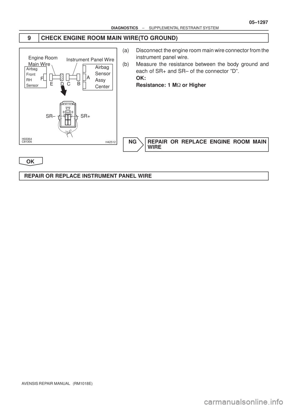
Engine Room
Main Wire
Airbag
Sensor
Assy
CenterAirbag
Front
RH
Sensor
Instrument Panel Wire
SR±SR+
A
B
C D E F
± DIAGNOSTICSSUPPLEMENTAL RESTRAINT SYSTEM
05±1297
AVENSIS REPAIR MANUAL (RM1018E)
9 CHECK ENGINE ROOM MAIN WIRE(TO GROUND)
(a) Disconnect the engine room main wire connector from the
instrument panel wire.
(b) Measure the resistance between the body ground and
each of SR+ and SR± of the connector ºDº.
OK:
Resistance: 1 M�or Higher
NG REPAIR OR REPLACE ENGINE ROOM MAIN
WIRE
OK
REPAIR OR REPLACE INSTRUMENT PANEL WIRE
Page 1359 of 5135
 (*1)
BBL± BCL+S14 (*1)
(*2)
(*1)
(*2)16
S14")
H42521
Side Airbag Sensor Assy LH
Airbag Sensor Assy Center
*1: w/ Curtain Shield Airbag
*2: w/o Curtain Shield AirbagBBL+
BBL± BBL+
BCL±A26 2 4
1 3(*2) (*1)
BBL± BCL+S14 (*1)
(*2)
(*1)
(*2)16
S14
S14S14
(*2) (*1)A2618 GR±L
LG±B 05±1288
± DIAGNOSTICSSUPPLEMENTAL RESTRAINT SYSTEM
AVENSIS REPAIR MANUAL (RM1018E)
DTC B1141/33 SIDE AIRBAG SENSOR ASSY (LH)
MALFUNCTION
CIRCUIT DESCRIPTION
The side airbag sensor assy LH consists of the diagnosis circuit and the lateral deceleration sensor, etc.
If the airbag sensor assy center receives signals from the lateral deceleration sensor, it judges whether or
not the SRS should be activated.
DTC B1141/33 is recorded when a malfunction in the side airbag sensor assy LH is detected.
DTC No.DTC Detecting ConditionTrouble Area
B1141/33
�Short circuit in side airbag sensor assy LH wire harness
(to B+)
�Short circuit in side airbag sensor assy LH wire harness
(to ground)
�Open circuit in BBL+ wire harness or BBL± wire harness of
side airbag sensor assy LH
�Side airbag sensor assy LH malfunction
�Airbag sensor assy center malfunction
�Side airbag sensor assy LH
�Airbag sensor assy center
�Floor wire
WIRING DIAGRAM
05C5Z±01
Page 1360 of 5135

������
������������������
������������H40445
Side
Airbag
Sensor
Assy LHAirbag
Sensor
Assy
Center
DLC3
CG TC
DTC B1141/33
±
DIAGNOSTICS SUPPLEMENTAL RESTRAINT SYSTEM
05±1289
AVENSIS REPAIR MANUAL (RM1018E)
INSPECTION PROCEDURE
1CHECK DTC
(a)Turn the ignition switch to the LOCK position.
(b)Disconnect the negative (±) terminal cable from the bat-
tery, and wait for at least 90 seconds.
(c)Connect the negative (±) terminal cable to the battery, and wait for at least 2 seconds.
(d)Turn the ignition switch to the ON position, and wait for at least 10 seconds.
(e)Clear the stored DTCs in the memory (See page 05±1184).
(f) Turn the ignition switch to the LOCK position.
(g) Turn the ignition switch to the ON position, and wait for at least 10 seconds.
(h)Check the DTCs (See page 05±1184). OK:
DTC B1141/33 is not output.
HINT:
Codes other than code B1141/33 may be output at this time, but
they are not related to this check.
NG Go to step 2
OK
USE SIMULATION METHOD TO CHECK
2 CHECK CONNECTION OF CONNECTORS
(a) Turn the ignition switch to the LOCK position.
(b) Disconnect the negative (±) terminal cable from the battery, and wait for at least 90 seconds.
(c) Check that the connectors are properly connected to the airbag sensor assy ce\
nter and the side airbag sensor assy LH.
OK:
The connectors are connected.
NG CONNECT CONNECTORS
OK
Page 1361 of 5135

�����
�����
�����
�����H42837
Airbag
Sensor
Assy
Center Floor Wire
Side
Airbag
Sensor
Assy LH
BBL± BBL+
w/o Curtain
Shield Airbag:w/ Curtain
Shield Airbag:
BCL±
BCL+BBL±
BBL+
A
B
C D
�����
�����
�����
�����H42231
Side
Airbag
Sensor
Assy LHAirbag
Sensor
Assy
Center
BBL±
BBL+Floor Wire
A
B C D
05±1290
± DIAGNOSTICSSUPPLEMENTAL RESTRAINT SYSTEM
AVENSIS REPAIR MANUAL (RM1018E)
3 CHECK FLOOR WIRE(OPEN)
(a) Disconnect the connectors from the airbag sensor assy
center and the side airbag sensor assy RH.
(b) w/ Curtain shield airbag:
Using a service wire, connect BCL+ and BCL± of the con-
nector ºCº.
NOTICE:
Do not forcibly insert a service wire into the terminal of the
connector when connecting.
(c) w/o Curtain shield airbag:
Using a service wire, connect BBL+ and BBL± of the con-
nector ºCº.
NOTICE:
Do not forcibly insert a service wire into the terminal of the
connector when connecting.
(d) Measure the resistance between BBL+ and BBL± of the
connector ºBº.
OK:
Resistance: Below 1 �
NG REPAIR OR REPLACE FLOOR WIRE
OK
4 CHECK FLOOR WIRE(TO B+)
(a) Disconnect the service wire from the connector ºCº.
(b) Connect the negative (±) terminal cable to the battery,
and turn the ignition switch to the ON position.
(c) Measure the voltage between the body ground and each
of BBL+ and BBL± of the connector ºBº.
OK:
Voltage: Below 1 V
NG REPAIR OR REPLACE FLOOR WIRE
OK
Page 1362 of 5135

�����
\b����
�����
\b����H42231
Side
Airbag
Sensor
Assy LH Airbag
Sensor
Assy
Center
BBL± BBL+Floor Wire
�����
�����
�����
�����
�����
�����
�����
�����H42116
Airbag
Sensor
Assy
Center
DLC3
CG TC DTC B1140/32
DTC B1141/33
Side
Airbag
Sensor
Assy RH
±
DIAGNOSTICS SUPPLEMENTAL RESTRAINT SYSTEM
05±1291
AVENSIS REPAIR MANUAL (RM1018E)
5CHECK FLOOR WIRE(TO GROUND)
(a)Turn the ignition switch to the LOCK position.
(b)Disconnect the negative (±) terminal cable from the bat-
tery, and wait for at least 90 seconds.
(c)Measure the resistance between the body ground and each of BBL+ and BBL± of the connector ºBº.
OK:
Resistance: 10 k � or Higher
NGREPAIR OR REPLACE FLOOR WIRE
OK
6CHECK SIDE AIR BAG SENSOR ASSY LH
(a)Turn the ignition switch to the LOCK position.
(b)Disconnect the negative (±) terminal cable from the bat- tery, and wait for at least 90 seconds.
(c)Connect the connector to the airbag sensor assy center.
(d)Interchange the side airbag sensor assy RH with LH and connect the connectors to them.
(e)Connect the negative (±) terminal cable to the battery, and wait for at least 2 seconds.
(f)Turn the ignition switch to the ON position, and wait for at least 10 seconds.
(g)Clear the stored DTCs in the memory (See page 05±1184).
(h) Turn the ignition switch to the LOCK position.
(i) Turn the ignition switch to the ON position, and wait for at least 10 seconds.
(j)Check the DTCs (See page 05±1184). OK:
A: DTC B1140/32 is not output.
B: DTC B1141/33 is not output.
NG:A REPLACE AIR BAG SENSOR ASSY CENTER
NG:B REPLACE SIDE AIR BAG SENSOR ASSY LH
OK
USE SIMULATION METHOD TO CHECK
Page 1363 of 5135
 (*1)
BBR± BCR+S15
S15 S15 (*1)
(")
H42521
Side Airbag Sensor Assy RH
Airbag Sensor Assy Center
*1: w/ Curtain Shield Airbag
*2: w/o Curtain Shield AirbagBBR+
BBR± BBR+
BCR±GR
PA2817
15 S152 4
1 3(*2) (*1)
BBR± BCR+S15
S15 S15 (*1)
(*2)
(*1)
(*2)
A28
(*2) (*1) 05±1284
± DIAGNOSTICSSUPPLEMENTAL RESTRAINT SYSTEM
AVENSIS REPAIR MANUAL (RM1018E)
DTC B1140/32 SIDE AIRBAG SENSOR ASSY (RH)
MALFUNCTION
CIRCUIT DESCRIPTION
The side airbag sensor assy RH consists of the diagnosis circuit and the lateral deceleration sensor, etc.
If the airbag sensor assy center receives signals from the lateral deceleration sensor, it judges whether or
not the SRS should be activated.
DTC B1140/32 is recorded when a malfunction in the side airbag sensor assy RH is detected.
DTC No.DTC Detecting ConditionTrouble Area
B1140/32
�Short circuit in side airbag sensor assy RH wire harness
(to B+)
�Short circuit in side airbag sensor assy RH wire harness
(to ground)
�Open circuit in BBR+ wire harness or BBR± wire harness of
side airbag sensor assy RH
�Side airbag sensor assy RH malfunction
�Airbag sensor assy center malfunction
�Side airbag sensor assy RH
�Airbag sensor assy center
�Floor wire No.2
WIRING DIAGRAM
05C5Y±01
Page 1364 of 5135

������������
������������������
������H40442
Side
Airbag
Sensor
Assy RH Airbag
Sensor
Assy
Center
DLC3
CGTC
DTC B1140/32
±
DIAGNOSTICS SUPPLEMENTAL RESTRAINT SYSTEM
05±1285
AVENSIS REPAIR MANUAL (RM1018E)
INSPECTION PROCEDURE
1CHECK DTC
(a)Turn the ignition switch to the LOCK position.
(b)Disconnect the negative (±) terminal cable from the bat-
tery, and wait for at least 90 seconds.
(c)Connect the negative (±) terminal cable to the battery, and wait for at least 2 seconds.
(d)Turn the ignition switch to the ON position, and wait for at least 10 seconds.
(e)Clear the stored DTCs in the memory (See page 05±1184).
(f) Turn the ignition switch to the LOCK position.
(g) Turn the ignition switch to the ON position, and wait for at least 10 seconds.
(h)Check the DTCs (See page 05±1184). OK:
DTC B1140/32 is not output.
HINT:
Codes other than code B1140/32 may be output at this time, but
they are not related to this check.
NG Go to step 2
OK
USE SIMULATION METHOD TO CHECK
2 CHECK CONNECTION OF CONNECTORS
(a) Turn the ignition switch to the LOCK position.
(b) Disconnect the negative (±) terminal cable from the battery, and wait for at least 90 seconds.
(c) Check that the connectors are properly connected to the airbag sensor assy ce\
nter and the side airbag sensor assy RH.
OK:
The connectors are connected.
NG CONNECT CONNECTORS
OK
Page 1365 of 5135

�����
�����
�����
�����H42838
Airbag
Sensor
Assy
Center Floor Wire No.2
BBR+
BBR±Side Airbag
Sensor Assy RH
w/o Curtain
Shield Airbag:w/ Curtain
Shield Airbag:
BBR+BBR±
BCR+
BCR±
A
B C D
����� �����
����� �����H42229
Side
Airbag
Sensor
Assy RHAirbag
Sensor
Assy
Center
BBR±
BBR+
Floor Wire No.2
A
B C D
05±1286
± DIAGNOSTICSSUPPLEMENTAL RESTRAINT SYSTEM
AVENSIS REPAIR MANUAL (RM1018E)
3 CHECK FLOOR WIRE NO.2(OPEN)
(a) Disconnect the connectors from the airbag sensor assy
center and the side airbag sensor assy RH.
(b) w/o Curtain shield airbag:
Using a service wire, connect BCR+ and BCR± of the con-
nector ºCº.
NOTICE:
Do not forcibly insert a service wire into the terminal of the
connector when connecting.
(c) w/ Curtain shield airbag:
Using a service wire, connect BBR+ and BBR± of the con-
nector ºCº.
NOTICE:
Do not forcibly insert a service wire into the terminal of the
connector when connecting.
(d) Measure the resistance between BBR+ and BBR± of the
connector ºBº.
OK:
Resistance: Below 1 �
NG REPAIR OR REPLACE FLOOR WIRE NO.2
OK
4 CHECK FLOOR WIRE NO.2(TO B+)
(a) Disconnect the service wire from the connector ºCº.
(b) Connect the negative (±) terminal cable to the battery,
and turn the ignition switch to the ON position.
(c) Measure the voltage between the body ground and each
of BBR+ and BBR± of the connector ºBº.
OK:
Voltage: Below 1 V
NG REPAIR OR REPLACE FLOOR WIRE NO.2
OK