Page 1366 of 5135

����� \b���\b
����� \b���\bH42229
Side
Airbag
Sensor
Assy RHAirbag
Sensor
Assy
Center
BBR±
BBR+
Floor Wire No.2
A
B
C
D
�����
�����
�����
�����
�����
�����
�����
�����H42115
Airbag
Sensor
Assy
Center
DLC3
CGTC DTC B1140/32
DTC B1141/33
Side
Airbag
Sensor
Assy LH
±
DIAGNOSTICS SUPPLEMENTAL RESTRAINT SYSTEM
05±1287
AVENSIS REPAIR MANUAL (RM1018E)
5CHECK FLOOR WIRE NO.2(TO GROUND)
(a)Turn the ignition switch to the LOCK position.
(b)Disconnect the negative (±) terminal cable from the bat-
tery, and wait for at least 90 seconds.
(c)Measure the resistance between the body ground and each of BBR+ and BBR± of the connector ºCº.
OK:
Resistance: 10 k � or Higher
NGREPAIR OR REPLACE FLOOR WIRE NO.2
OK
6CHECK SIDE AIR BAG SENSOR ASSY RH
(a)Turn the ignition switch to the LOCK position.
(b)Disconnect the negative (±) terminal cable from the bat- tery, and wait for at least 90 seconds.
(c)Connect the connector to the airbag sensor assy center.
(d)Interchange the side airbag sensor assy RH with LH and connect the connectors to them.
(e)Connect the negative (±) terminal cable to the battery, and wait for at least 2 seconds.
(f)Turn the ignition switch to the ON position, and wait for at least 10 seconds.
(g)Clear the stored DTCs in the memory (See page 05±1184).
(h) Turn the ignition switch to the LOCK position.
(i) Turn the ignition switch to the ON position, and wait for at least 10 seconds.
(j)Check the DTCs (See page 05±1184). OK:
A: DTC B1140/32 is not output.
B: DTC B1141/33 is not output.
NG:A REPLACE SIDE AIR BAG SENSOR ASSY RH
NG:B REPLACE AIR BAG SENSOR ASSY CENTER
OK
USE SIMULATION METHOD TO CHECK
Page 1367 of 5135

DTCB1100/31AIRBAG SENSOR ASSY CENTER MALFUNCTION
CIRCUIT DESCRIPTION
The ai")
������H41086
DLC3
CG TC DTC B1100/31
05±1282
±
DIAGNOSTICS SUPPLEMENTAL RESTRAINT SYSTEM
AVENSIS REPAIR MANUAL (RM1018E)
DTCB1100/31AIRBAG SENSOR ASSY CENTER MALFUNCTION
CIRCUIT DESCRIPTION
The airbag sensor assy center consists of the airbag sensor, the safing sensor, the drive circuit, the diagnosis
circuit and the ignition control, etc.
If the airbag sensor assy center receives signals from the airbag sensor, it judges whether or not the SRS
should be activated.
DTC B1100/31 is recorded when a malfunction in the airbag sensor assy center i\
s detected.
DTC No.DTC Detecting ConditionTrouble Area
B1100/31�Airbag sensor assy center malfunction
� Half connection detection malfunction�Airbag sensor assy center
� Airbag sensor assy center connector
HINT:
When a malfunction code other than code B1100/31 is displayed at the same time, first repair the malfunction
indicated by the malfunction code other than code B1100/31.
INSPECTION PROCEDURE
1CHECK DTC
(a)Turn the ignition switch to the LOCK position.
(b)Disconnect the negative (±) terminal cable from the bat-
tery, and wait for at least 90 seconds.
(c)Connect the negative (±) terminal cable to the battery,
and wait for at least 2 seconds.
(d)Turn the ignition switch to the ON position, and wait for at least 10 seconds.
(e)Clear the stored DTCs in the memory (See page
05±1184).
(f) Turn the ignition switch to the LOCK position.
(g) Turn the ignition switch to the ON position, and wait for at least 10 seconds.
(h)Check the DTCs (See page 05±1184). OK:
DTC B1100/31 is not output.
HINT:
Codes other than code B1100/31 may be output at this time, but
they are not related to this check.
NG Go to step 2
OK
USE SIMULATION METHOD TO CHECK
05C5X±01
Page 1368 of 5135

2CHECK CONNECTOR
(a)Turn the igniti")
H40441
Disconnection Detection Pin
������������H41086
DLC3DTC B1100/31
CG TC
±
DIAGNOSTICS SUPPLEMENTAL RESTRAINT SYSTEM
05±1283
AVENSIS REPAIR MANUAL (RM1018E)
2CHECK CONNECTOR
(a)Turn the ignition switch to the LOCK position.
(b)Disconnect the negative (±) terminal cable from the battery, and wait for at least 90 seconds.
(c)Check the connection of the airbag sensor assy center connectors.
OK:
The connectors are connected.
NGCONNECT CONNECTORS, THEN GO TO STEP1
OK
3PERFORM A VISUAL CHECK OF THE DISCONNECTION DETECTION PIN
(a)Check that the disconnection detection pin is not de- formed.
OK:
The connectors are not deformed.
NGREPAIR OR REPLACE AIRBAG SENSOR ASSY CENTER CONNECTOR
OK
4CHECK AIR BAG SENSOR ASSY CENTER
(a)Connect the negative (±) terminal cable to the battery, and wait for at least 2 seconds.
(b)Turn the ignition switch to the ON position, and wait for at least 10 seconds.
(c)Clear the stored DTCs in the memory (See page 05±1184).
(d) Turn the ignition switch to the LOCK position.
(e) Turn the ignition switch to the ON position, and wait for at least 10 seconds.
(f)Check the DTCs (See page 05±1184).
OK:
DTC B1100/31 is not output.
HINT:
Codes other than code B1100/31 may be output at this time, but
they are not related to this check.
NG REPLACE AIR BAG SENSOR ASSY CENTER
OK
USE SIMULATION METHOD TO CHECK
Page 1369 of 5135

DTC B0138/72 SHORT IN P/T")
������������H40056
P/T Squib LHPL±
PL+ Airbag
Sensor
Assy
CenterFloor Wire
A
B
C
D
±
DIAGNOSTICS SUPPLEMENTAL RESTRAINT SYSTEM
05±1279
AVENSIS REPAIR MANUAL (RM1018E)
DTC B0138/72 SHORT IN P/T SQUIB (LH) CIRCUIT (TO B+)
CIRCUIT DESCRIPTION
The P/T squib LH circuit consists of the airbag sensor assy center and the \
front seat outer belt assy LH (seat
belt pretensioner LH).
This circuit actuates the SRS to deploy when the SRS deployment conditio\
ns are fulfilled.
DTC B0138/72 is recorded when a short to B+ is detected in the P/T squib\
LH circuit.
DTC No.DTC Detecting ConditionTrouble Area
B0138/72
�Short circuit in P/T squib LH wire harness (to B+)
� P/T squib LH malfunction
� Airbag sensor assy center malfunction�Front seat outer belt assy LH (P/T squib LH)
� Airbag sensor assy center
� Floor wire
WIRING DIAGRAM
See page 05±1270.
INSPECTION PROCEDURE
1 CHECK FLOOR WIRE(P/T SQUIB LH CIRCUIT)
(a) Turn the ignition switch to the LOCK position.
(b) Disconnect the negative (±) terminal cable from the bat-
tery, and wait for at least 90 seconds.
(c) Disconnect the connectors from the airbag sensor assy center and the front seat outer belt assy LH.
(d) Connect the negative (±) terminal cable to the battery, and turn the ignition switch to the ON position.
(e) Measure the voltage between the body ground and PL+ of the connector ºCº.
OK:
Voltage: Below 1 V
NG REPAIR OR REPLACE FLOOR WIRE
OK
054M6±07
Page 1370 of 5135

�����\b
����
������ ���� �
H40957
P/T Squib LHDLC3 TC
CG
DTC B0138/72
Airbag
Sensor
Assy
Center
PL±
PL+
Floor Wire
Service Wire
C
D
05±1280
±
DIAGNOSTICS SUPPLEMENTAL RESTRAINT SYSTEM
AVENSIS REPAIR MANUAL (RM1018E)
2 CHECK AIR BAG SENSOR ASSY CENTER
(a) Turn the ignition switch to the LOCK position.
(b) Disconnect the negative (±) terminal cable from the bat- tery, and wait for at least 90seconds.
(c) Connect the connector to the airbag sensor assy center.
(d) Using a service wire, connect PL+ and PL± of the connec- tor ºCº.
NOTICE:
Do not forcibly insert a service wire into the terminal of the
connector when connecting.
(e) Connect the negative (±) terminal cable to the battery, and wait for at least 2 seconds.
(f) Turn the ignition switch to the ON position, and wait for at least 10 seconds.
(g)Clear the stored DTCs in the memory (See page 05±1184).
(h) Turn the ignition switch to the LOCK position.
(i) Turn the ignition switch to the ON position, and wait for at
least 10 seconds.
(j)Check the DTCs (See page 05±1184). OK:
DTC B0138/72 is not output.
HINT:
Codes other than code B0138/72 may be output at this time, but
they are not related to this check.
NG REPLACE AIR BAG SENSOR ASSY CENTER
OK
Page 1371 of 5135

3 CHECK FRONT SEA")
������ ������������H40064
P/T Squib LHDLC3
DTC B0138/72
CG TC Airbag
Sensor
Assy
Center
C
D
±
DIAGNOSTICS SUPPLEMENTAL RESTRAINT SYSTEM
05±1281
AVENSIS REPAIR MANUAL (RM1018E)
3 CHECK FRONT SEAT OUTER BELT ASSY LH(P/T SQUIB LH)
(a) Turn the ignition switch to the LOCK position.
(b) Disconnect the negative (±) terminal cable from the bat-
tery, and wait for at least 90 seconds.
(c) Connect the connector to the front seat outer belt assy LH.
(d) Connect the negative (±) terminal cable to the battery, and wait for at least 2 seconds.
(e) Turn the ignition switch to the ON position, and wait for at least 10 seconds.
(f)Clear the stored DTCs in the memory (See page 05±1184).
(g) Turn the ignition switch to the LOCK position.
(h) Turn the ignition switch to the ON position, and wait for at least 10 seconds.
(i)Check the DTCs (See page 05±1184). OK:
DTC B0138/72 is not output.
HINT:
Codes other than code B0138/72 may be output at this time, but
they are not related to this check.
NG REPLACE FRONT SEAT OUTER BELT ASSY LH
OK
4 USE SIMULATION METHOD TO CHECK
NG Go to step 1
OK
REPLACE ALL SRS COMPONENTS INCLUDING WIRE HARNESS
Page 1372 of 5135
Airbag
Sensor
Assy
Center
P2+
Instrument Panel Wire
A
B
C
D
05±1368
±
DIAGNOSTICS SUPPLEMENTAL RESTRAINT SYSTEM
AVENSIS REPAIR MANUAL (RM1018E)
DTC B1187/55")
������������H40584
P Squib
(2nd step)Airbag
Sensor
Assy
Center
P2+
Instrument Panel Wire
A
B
C
D
05±1368
±
DIAGNOSTICS SUPPLEMENTAL RESTRAINT SYSTEM
AVENSIS REPAIR MANUAL (RM1018E)
DTC B1187/55 SHORT IN P SQUIB (2ND STEP) CIRCUIT (TO GROUND)
CIRCUIT DESCRIPTION
The P squib (2nd step) circuit consists of the airbag sensor assy center \
and the instrument panel passenger
airbag assy.
This circuit actuates the SRS to deploy when the SRS deployment conditio\
ns are fulfilled.
DTC B1187/55 is recorded when a short to ground is detected in the P squib (2\
nd step) circuit.
DTC No.DTC Detecting ConditionTrouble Area
B1187/55
�Short circuit in P squib (2nd step) wire harness (to ground)
� P squib (2nd step) malfunction
� Airbag sensor assy center malfunction�Instrument panel passenger airbag assy (P squib, 2nd step)
� Airbag sensor assy center
� Instrument panel wire
WIRING DIAGRAM
See page 05±1362.
INSPECTION PROCEDURE
1 CHECK INSTRUMENT PANEL WIRE(P SQUIB, 2ND STEP CIRCUIT)
(a) Turn the ignition switch to the LOCK position.
(b) Disconnect the negative (±) terminal cable from the bat-
tery, and wait for at least 90 seconds.
(c) Disconnect the connectors from the airbag sensor assy center and the instrument panel passenger airbag assy.
(d) Measure the resistance between the body ground and
P2+ of the connector ºCº.
OK:
Resistance: 1 M � or Higher
NG REPAIR OR REPLACE INSTRUMENT PANEL WIRE
OK
056MZ±03
Page 1373 of 5135
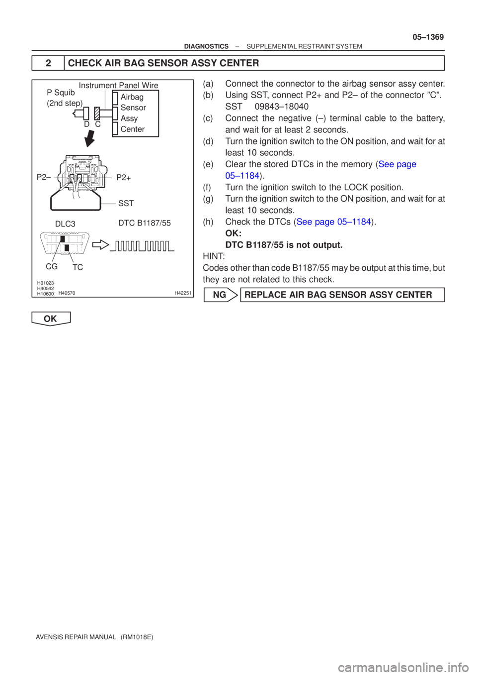
����� ����� ����� ���\b�H42251
Airbag
Sensor
Assy
Center
P2+
P2±
DLC3 DTC B1187/55
TC
CGP Squib
(2nd step)Instrument Panel Wire
SST
C
D
±
DIAGNOSTICS SUPPLEMENTAL RESTRAINT SYSTEM
05±1369
AVENSIS REPAIR MANUAL (RM1018E)
2CHECK AIR BAG SENSOR ASSY CENTER
(a)Connect the connector to the airbag sensor assy center.
(b)Using SST, connect P2+ and P2± of the connector ºCº.
SST09843±18040
(c)Connect the negative (±) terminal cable to the battery, and wait for at least 2 seconds.
(d)Turn the ignition switch to the ON position, and wait for at least 10 seconds.
(e)Clear the stored DTCs in the memory (See page 05±1184).
(f) Turn the ignition switch to the LOCK position.
(g) Turn the ignition switch to the ON position, and wait for at least 10 seconds.
(h)Check the DTCs (See page 05±1184). OK:
DTC B1187/55 is not output.
HINT:
Codes other than code B1187/55 may be output at this time, but
they are not related to this check.
NG REPLACE AIR BAG SENSOR ASSY CENTER
OK