Page 5103 of 5135
600A7–04
H42767
60–4– SUPPLEMENTAL RESTRAINT SYSTEMSIDE AIR BAG SENSOR ASSY LH (From February,
2004)
AVENSIS REPAIR MANUAL SUPPLEMENT
(RM1098E)
REPLACEMENT
HINT:
Use the same procedures for the RH side and LH side.
1. PRECAUTION (SEE PUB. NO. RM1018E, PAGE 60–1)
2. DISCONNECT BATTERY NEGATIVE TERMINAL
CAUTION:
After removing the terminal, wait for at least 90 seconds before starting the operation.
3. REMOVE FRONT DOOR SCUFF PLATE LH (SEE PUB. NO. RM1018E, PAGE 76–36)
4. REMOVE REAR DOOR SCUFF PLATE LH (SEE PUB. NO. RM1018E, PAGE 76–36)
5. REMOVE FRONT DOOR WEATHERSTRIP LH (SEE PUB. NO. RM1018E, PAGE 76–36)
6. REMOVE REAR DOOR WEATHERSTRIP LH (SEE PUB. NO. RM1018E, PAGE 76–36)
7. REMOVE CENTER PILLAR GARNISH LOWER LH (SEE PUB. NO. RM1018E, PAGE 76–36)
8. REMOVE FRONT SEAT OUTER BELT ASSY LH (SEE PUB. NO. RM1018E, PAGE 61–7)
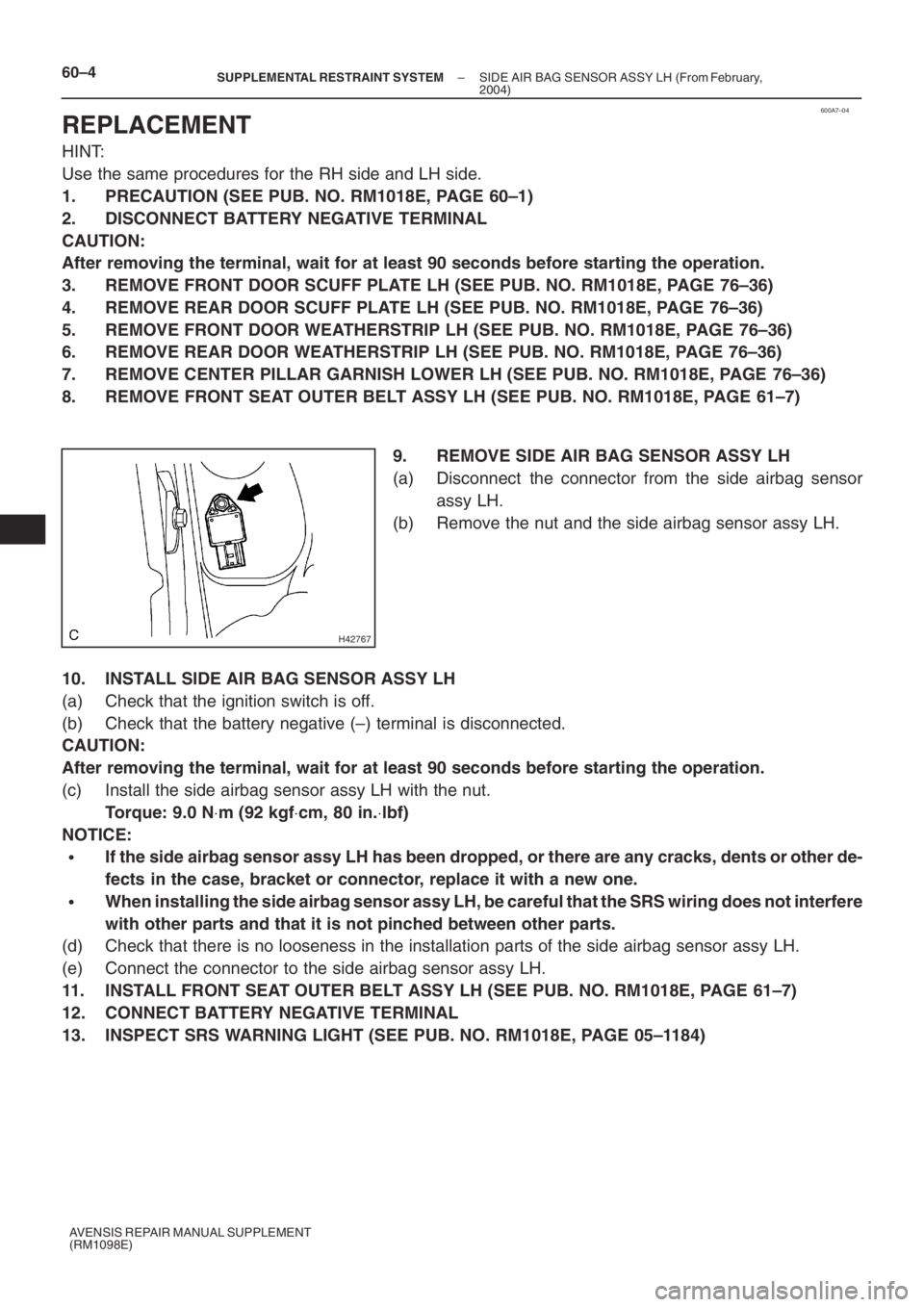
9. REMOVE SIDE AIR BAG SENSOR ASSY LH
(a) Disconnect the connector from the side airbag sensor
assy LH.
(b) Remove the nut and the side airbag sensor assy LH.
10. INSTALL SIDE AIR BAG SENSOR ASSY LH
(a) Check that the ignition switch is off.
(b) Check that the battery negative (–) terminal is disconnected.
CAUTION:
After removing the terminal, wait for at least 90 seconds before starting the operation.
(c) Install the side airbag sensor assy LH with the nut.
Torque: 9.0 N⋅m (92 kgf⋅cm, 80 in.⋅lbf)
NOTICE:
�If the side airbag sensor assy LH has been dropped, or there are any cracks, dents or other de-
fects in the case, bracket or connector, replace it with a new one.
�When installing the side airbag sensor assy LH, be careful that the SRS wiring does not interfere
with other parts and that it is not pinched between other parts.
(d) Check that there is no looseness in the installation parts of the side airbag sensor assy LH.
(e) Connect the connector to the side airbag sensor assy LH.
11. INSTALL FRONT SEAT OUTER BELT ASSY LH (SEE PUB. NO. RM1018E, PAGE 61–7)
12. CONNECT BATTERY NEGATIVE TERMINAL
13. INSPECT SRS WARNING LIGHT (SEE PUB. NO. RM1018E, PAGE 05–1184)
Page 5105 of 5135
600K6–02
H42699
60–2
– SUPPLEMENTAL RESTRAINT SYSTEMAIR BAG SENSOR FRONT LH (From February, 2004)
AVENSIS REPAIR MANUAL SUPPLEMENT
(RM1098E)
REPLACEMENT
HINT:
Use the same procedures for the RH side and LH side.
1. PRECAUTION (SEE PUB. NO. RM1018E, PAGE 60–1)
2. DISCONNECT BATTERY NEGATIVE TERMINAL
CAUTION:
After removing the terminal, wait for at least 90 seconds before starting the operation.
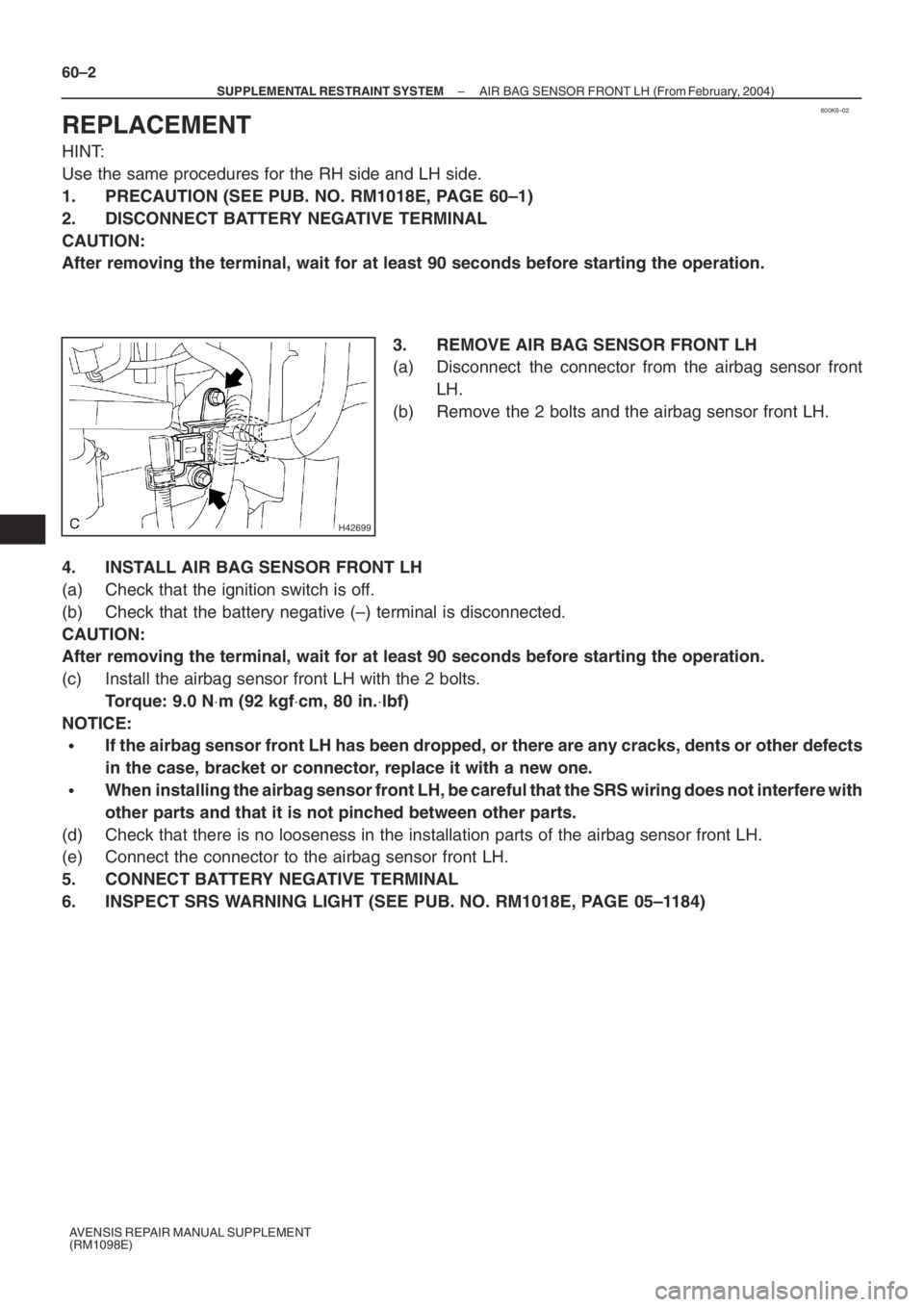
3. REMOVE AIR BAG SENSOR FRONT LH
(a) Disconnect the connector from the airbag sensor front
LH.
(b) Remove the 2 bolts and the airbag sensor front LH.
4. INSTALL AIR BAG SENSOR FRONT LH
(a) Check that the ignition switch is off.
(b) Check that the battery negative (–) terminal is disconnected.
CAUTION:
After removing the terminal, wait for at least 90 seconds before starting the operation.
(c) Install the airbag sensor front LH with the 2 bolts.
Torque: 9.0 N⋅m (92 kgf⋅cm, 80 in.⋅lbf)
NOTICE:
�If the airbag sensor front LH has been dropped, or there are any cracks, dents or other defects
in the case, bracket or connector, replace it with a new one.
�When installing the airbag sensor front LH, be careful that the SRS wiring does not interfere with
other parts and that it is not pinched between other parts.
(d) Check that there is no looseness in the installation parts of the airbag sensor front LH.
(e) Connect the connector to the airbag sensor front LH.
5. CONNECT BATTERY NEGATIVE TERMINAL
6. INSPECT SRS WARNING LIGHT (SEE PUB. NO. RM1018E, PAGE 05–1184)
Page 5109 of 5135
A95725
Plastigage
A95726
Front Mark
A95724
SST
A65715
Paint Mark90� Engine
Front
A95724
SST
– ENGINE MECHANICALCYLINDER BLOCK ASSY (1ZZ–FE/3ZZ–FE)
14–53
1ZZ–FE,3ZZ–FE ENGINE REPAIR MANUAL
(RM1099E)
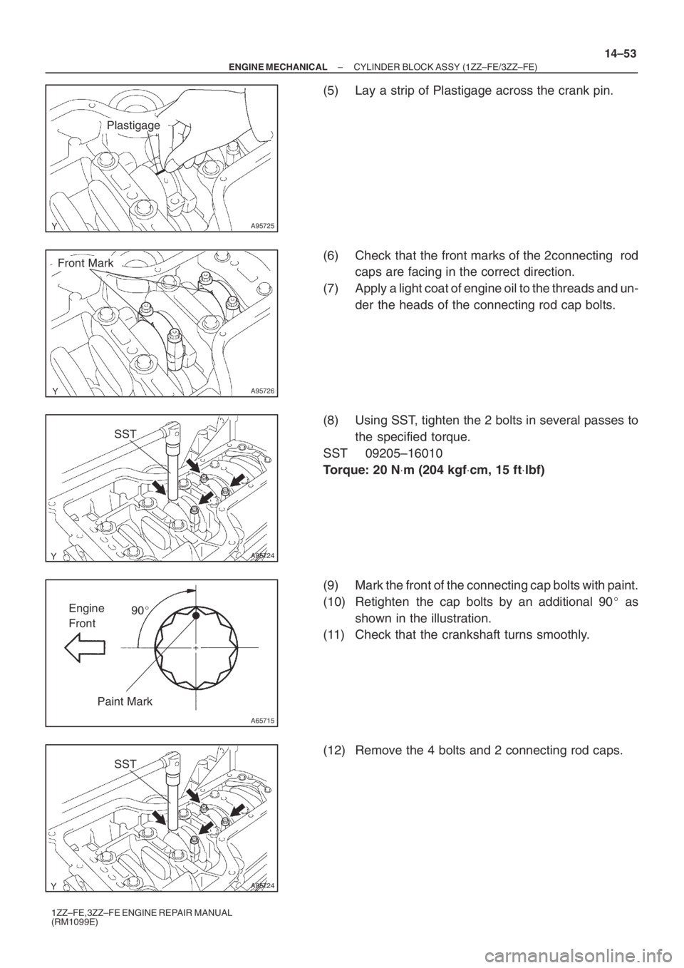
(5) Lay a strip of Plastigage across the crank pin.
(6) Check that the front marks of the 2connecting rod
caps are facing in the correct direction.
(7) Apply a light coat of engine oil to the threads and un-
der the heads of the connecting rod cap bolts.
(8) Using SST, tighten the 2 bolts in several passes to
the specified torque.
SST 09205–16010
Torque: 20 N⋅m (204 kgf⋅cm, 15 ft⋅lbf)
(9) Mark the front of the connecting cap bolts with paint.
(10) Retighten the cap bolts by an additional 90� as
shown in the illustration.
(11) Check that the crankshaft turns smoothly.
(12) Remove the 4 bolts and 2 connecting rod caps.
Page 5111 of 5135
A95721
Matchmark
A95723
SST
A01159
Plastigage
A95727
Front Mark
– ENGINE MECHANICALCYLINDER BLOCK ASSY (1ZZ–FE/3ZZ–FE)
14–55
1ZZ–FE,3ZZ–FE ENGINE REPAIR MANUAL
(RM1099E)
(d) Measure the oil clearance of the No. 1 and No. 4 cylin-
ders.
NOTICE:
Do not turn the crankshaft during the measurement.
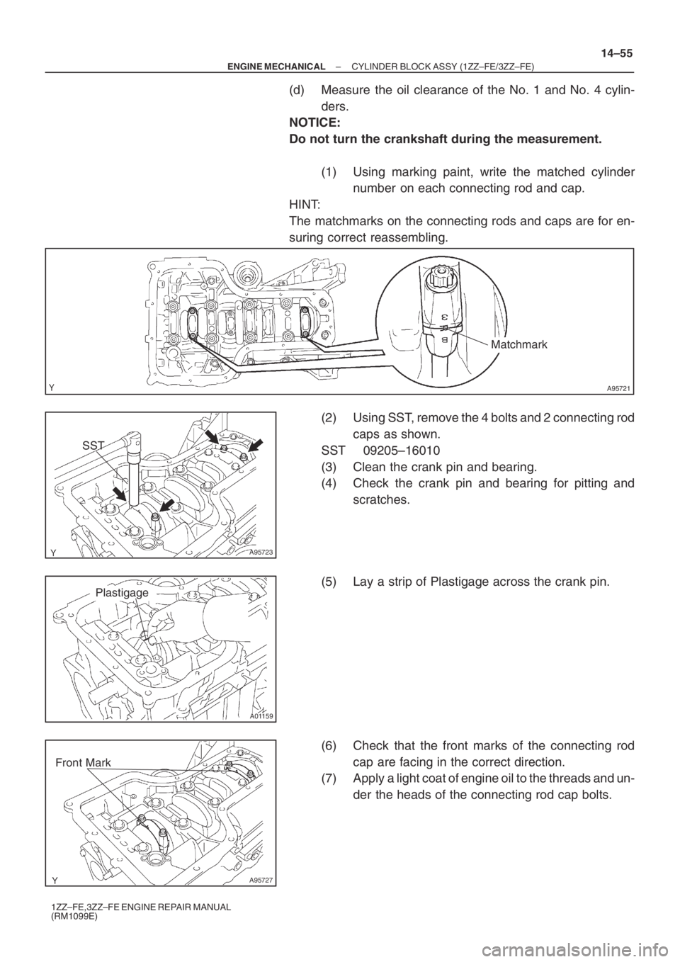
(1) Using marking paint, write the matched cylinder
number on each connecting rod and cap.
HINT:
The matchmarks on the connecting rods and caps are for en-
suring correct reassembling.
(2) Using SST, remove the 4 bolts and 2 connecting rod
caps as shown.
SST 09205–16010
(3) Clean the crank pin and bearing.
(4) Check the crank pin and bearing for pitting and
scratches.
(5) Lay a strip of Plastigage across the crank pin.
(6) Check that the front marks of the connecting rod
cap are facing in the correct direction.
(7) Apply a light coat of engine oil to the threads and un-
der the heads of the connecting rod cap bolts.
Page 5115 of 5135
A01192
A63898
A01179
A64817
A64968
793
481062
15
– ENGINE MECHANICALCYLINDER BLOCK ASSY (1ZZ–FE/3ZZ–FE)
14–59
1ZZ–FE,3ZZ–FE ENGINE REPAIR MANUAL
(RM1099E)
7. REMOVE W/PIN PISTON SUB–ASSY
(a) Using a small screwdriver, pry out the 2 snap rings.
(b) Heat the piston up to 80 to 90�C (176 to 194�F).
(c) Using a plastic hammer and brass bar, lightly tap out the
piston pin, then remove the connecting rod.
HINT:
�The piston and pin are a matched set.
�Arrange the piston, pins, ring, connecting rod and bear-
ings in the correct order.
8. REMOVE CRANKSHAFT
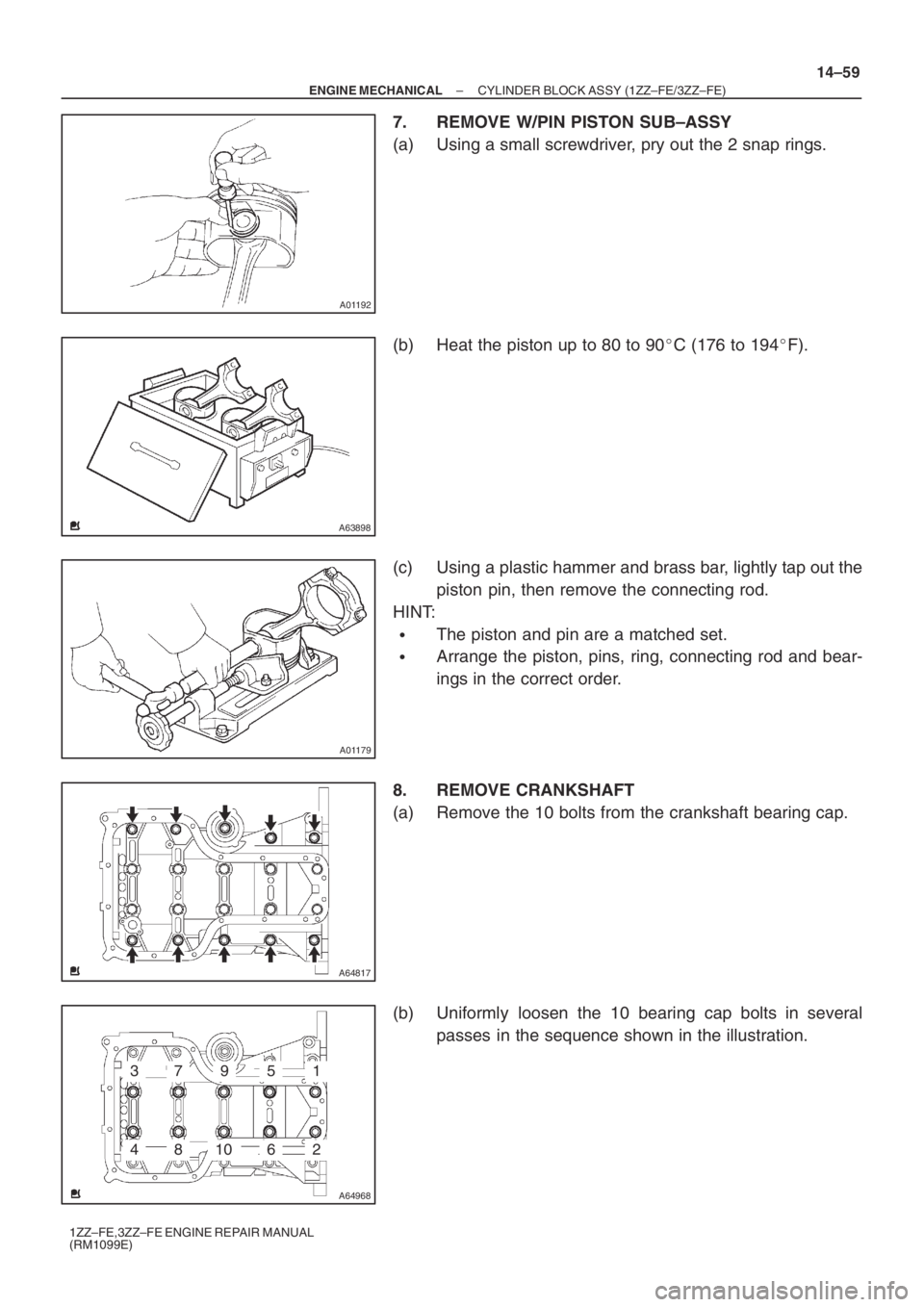
(a) Remove the 10 bolts from the crankshaft bearing cap.
(b) Uniformly loosen the 10 bearing cap bolts in several
passes in the sequence shown in the illustration.
Page 5130 of 5135
A64820
A01038
Seal Packing
A64968
793
481062
15
A65715
Paint Mark90� Engine
Front
14–74
– ENGINE MECHANICALCYLINDER BLOCK ASSY (1ZZ–FE/3ZZ–FE)
1ZZ–FE,3ZZ–FE ENGINE REPAIR MANUAL
(RM1099E)
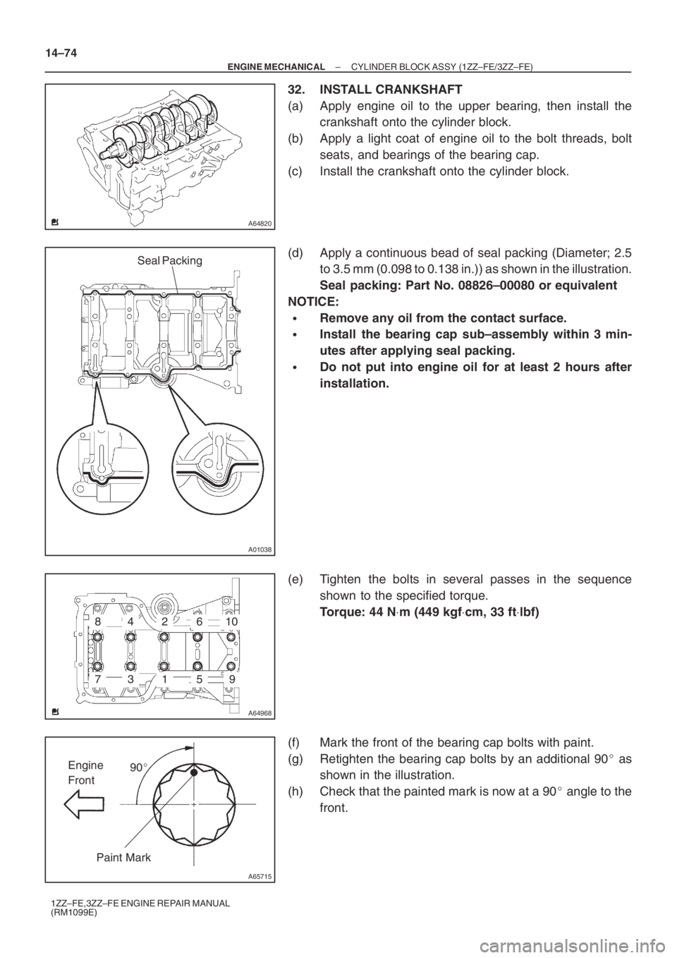
32. INSTALL CRANKSHAFT
(a) Apply engine oil to the upper bearing, then install the
crankshaft onto the cylinder block.
(b) Apply a light coat of engine oil to the bolt threads, bolt
seats, and bearings of the bearing cap.
(c) Install the crankshaft onto the cylinder block.
(d) Apply a continuous bead of seal packing (Diameter; 2.5
to 3.5 mm (0.098 to 0.138 in.)) as shown in the illustration.
Seal packing: Part No. 08826–00080 or equivalent
NOTICE:
�Remove any oil from the contact surface.
�Install the bearing cap sub–assembly within 3 min-
utes after applying seal packing.
�Do not put into engine oil for at least 2 hours after
installation.
(e) Tighten the bolts in several passes in the sequence
shown to the specified torque.
Torque: 44 N⋅m (449 kgf⋅cm, 33 ft⋅lbf)
(f) Mark the front of the bearing cap bolts with paint.
(g) Retighten the bearing cap bolts by an additional 90� as
shown in the illustration.
(h) Check that the painted mark is now at a 90� angle to the
front.
Page 5132 of 5135
A62813
Front Mark
Piston Ring
Compressor
A65713
Front Mark
A65714
SST
A65715
Paint Mark90� Engine
Front
A64845
14–76
– ENGINE MECHANICALCYLINDER BLOCK ASSY (1ZZ–FE/3ZZ–FE)
1ZZ–FE,3ZZ–FE ENGINE REPAIR MANUAL
(RM1099E)
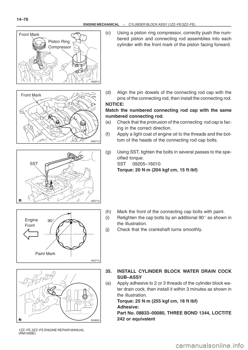
(c) Using a piston ring compressor, correctly push the num-
bered piston and connecting rod assemblies into each
cylinder with the front mark of the piston facing forward.
(d) Align the pin dowels of the connecting rod cap with the
pins of the connecting rod, then install the connecting rod.
NOTICE:
Match the numbered connecting rod cap with the same
numbered connecting rod.
(e) Check that the protrusion of the connecting rod cap is fac-
ing in the correct direction.
(f) Apply a light coat of engine oil to the threads and the bot-
tom of the heads of the connecting rod cap bolts.
(g) Using SST, tighten the bolts in several passes to the spe-
cified torque.
SST 09205–16010
Torque: 20 N⋅m (204 kgf⋅cm, 15 ft⋅lbf)
(h) Mark the front of the connecting cap bolts with paint.
(i) Retighten the cap bolts by an additional 90� as shown in
the illustration.
(j) Check that the crankshaft turns smoothly.
35. INSTALL CYLINDER BLOCK WATER DRAIN COCK
SUB–ASSY
(a) Apply adhesive to 2 or 3 threads of the cylinder block wa-
ter drain cock, then install it within 3 minutes as shown in
the illustration.
Torque: 25 N⋅m (255 kgf⋅cm, 18 ft⋅lbf)
Adhesive:
Part No. 08833–00080, THREE BOND 1344, LOCTITE
242 or equivalent