Page 694 of 5135

A72924
FreePushed in
432
1
Stop Lamp Switch
A80995
Brake Pedal
Depressed Brake Pedal
Released
ST1± (+)
E1 (±)
ECM ConnectorE12
E10
±
DIAGNOSTICS ECD SYSTEM(1CD±FTV)
05±645
AVENSIS REPAIR MANUAL (RM1018E)
1CHECK OPERATION OF STOP LIGHT
(a)Check if the stop lights go on and off normally when the brake pedal is depressed and released.
NGREPAIR OR REPLACE STOP LAMP SWITCHCIRCUIT
OK
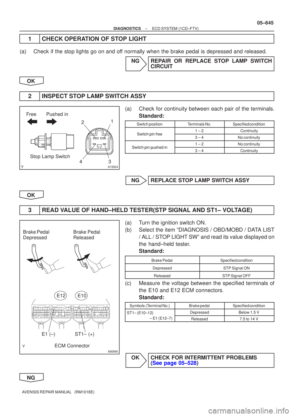
2INSPECT STOP LAMP SWITCH ASSY
(a)Check for continuity between each pair of the terminals. Standard:
Switch positionTerminals No.Specified condition
Switchpinfree1 ± 2ContinuitySwitch pin free3 ± 4No continuity
Switchpinpushedin1 ± 2No continuitySwitch pin pushed in3 ± 4Continuity
NGREPLACE STOP LAMP SWITCH ASSY
OK
3READ VALUE OF HAND±HELD TESTER(STP SIGNAL AND ST1± VOLTAGE)
(a)Turn the ignition switch ON.
(b)Select the item ºDIAGNOSIS / OBD/MOBD / DATA LIST / ALL / STOP LIGHT SWº and read its value displayed on
the hand±held tester.
Standard:
Brake PedalSpecified condition
DepressedSTP Signal ON
ReleasedSTP Signal OFF
(c)Measure the voltage between the specified terminals ofthe E10 and E12 ECM connectors.
Standard:
Symbols (Terminal No.)Brake pedalSpecified condition
ST1± (E10±12) DepressedBelow 1.5 VST1 (E1012)
± E1 (E12±7)
Released7.5 to 14 V
OKCHECK FOR INTERMITTENT PROBLEMS (See page 05±528)
NG
Page 780 of 5135
F45090
Driver Side J/BECU±IG
F45088GNDGNDIG1
05±728
±
DIAGNOSTICS ABS WITH EBD SYSTEM
AVENSIS REPAIR MANUAL (RM1018E)
INSPECTION PROCEDURE
1INSPECT FUSE(ECU±IG FUSE)
(a)Remove the ECU±IG fuse from the driver side J/B.
(b)Check continuity of the ECU±IG fuse. OK:
Continuity
NGINSPECT FOR SHORT CIRCUIT IN ALL HARNESS AND COMPONENTS CONNECTED
TO ECU±IG FUSE
OK
2INSPECT BATTERY
OK:
Voltage: 10 to 14 V NGINSPECT CHARGING SYSTEM
OK
3INSPECT SKID CONTROL ECU CONNECTOR(IG1 TERMINAL VOLTAGE)
IN CASE OF USING HAND±HELD TESTER:
(a)Check the voltage condition, which is output from the ECU and displayed \
on the hand±held tester. OK:
ºNormalº is displayed. IN CASE OF NOT USING HAND±HELD TESTER:
(a)Disconnect the skid control ECU connector.
(b)Turn the ignition switch ON.
(c)Measure the voltage between terminals IG1and GND ofthe skid control ECU harness side connector.
OK:
Voltage: 10 to 14 V
OKREPLACE BRAKE ACTUATOR ASSY (See page 32±54)
NG
Page 782 of 5135
±
DIAGNOSTICS ABS WITH EBD SYSTEM
05±725
AVENSIS REPAIR MANUAL (RM1018E)
DTCC1237/37SPEED SENSOR ROTOR FAULTY
CIRCUIT DESCRIPTION
DTC No.DTC Detecting ConditionTrouble Area
C1237/37
Detection of any of conditions from 1 through 4:
1.Wheel speed deviation of unspecified wheel.
2.Wheel sensor signal failure suspicion.
3.Continuous ABS control for 60 sec. or more.
�Speed sensor
� Sensorrotor
INSPECTION PROCEDURE
1INSPECT TIRE SIZE
NGREPLACE TIRES SO THAT ALL 4 TIRES ARE
SAME IN SIZE
OK
2INSPECT SPEED SENSOR ROTOR
NGREPLACE SENSOR ROTOR
OK
3INSPECT SPEED SENSOR
NGREPLACE SPEED SENSOR
OK
4CHECK HARNESS AND CONNECTOR(SPEED SENSOR ± SKID CONTROL ECU)
(a)Check for an open or short circuit in harness and connector between each term\
inal of speed sensor and the skid control ECU (See page 01±32).
NG REPAIR OR REPLACE HARNESS ORCONNECTOR
OK
REPLACE BRAKE ACTUATOR ASSY(See page 32±54)
0577V±04
Page 790 of 5135
05±718
±
DIAGNOSTICS ABS WITH EBD SYSTEM
AVENSIS REPAIR MANUAL (RM1018E)
INSPECTION PROCEDURE
1RECONFIRM DTC
(a)Check if other DTCs are detected (See page 05±699). YES REPAIR CIRCUIT INDICATED BY OUTPUTCODE
NO
REPLACE BRAKE ACTUATOR ASSY(See page 32±54)
Page 791 of 5135

F45131
Skid Control ECU
with Actuator
2 1 G R
177
RL+
RL±
S2 S2
A32
ABS Speed Sensor
Rear LH
8
19
S2 S2RR+ RR±
R
A33
ABS Speed Sensor
Rear RH 2 1
V G
P 2
1
110 IB1
IB1
IM1IE2 V P
V
P
IM1IE2 1011
±
DIAGNOSTICS ABS WITH EBD SYSTEM
05±713
AVENSIS REPAIR MANUAL (RM1018E)
DTCC0210/33RIGHT REAR SPEED SENSOR
DTCC0215/34LEFT REAR SPEED SENSOR
DTCC1332/38RIGHT REAR SPEED SENSOR CIRCUIT
DTCC1333/39LEFT REAR SPEED SENSOR CIRCUIT
CIRCUIT DESCRIPTION
Refer to DTC C0200/31, C0205/32, C1330/35, C1331/36 on page 05±709.
DTC No.DTC Detecting ConditionTrouble Area
C0210/33
C0215/34
When any of the following 1 to 3 is detected :
1. Non±plausible high frequent signal, high wheel accelera-
tion or high gradient for 20 sec. with the brake pedal
applied or for 5 sec. when the brake pedal is not applied.
2. After the initial start or restart and when the vehicle
speed has reached 12 km/h (7 mph), the wheel speed of
0 km/h (0 mph) is detected.
3. Deviation of 2 wheel speed.
� Right rear and left rear speed sensor
� Speed sensor rotor
C1332/38
C1333/39Detecting abnormality in the resistance value of each speed
sensor.�Right rear and left rear speed sensor
� Speed sensor circuit
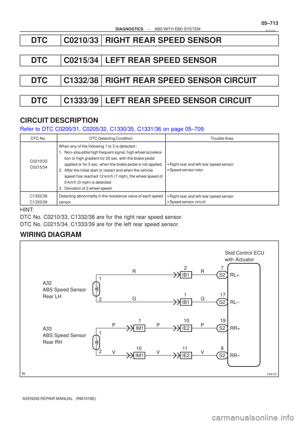
HINT:
DTC No. C0210/33, C1332/38 are for the right rear speed sensor.
DTC No. C0215/34, C1333/39 are for the left rear speed sensor.
WIRING DIAGRAM
0577U±04
Page 793 of 5135

W04200
Normal Signal Waveform
1 V / Division 2 m/s / Division GND
F10178OK
NG
±
DIAGNOSTICS ABS WITH EBD SYSTEM
05±715
AVENSIS REPAIR MANUAL (RM1018E)
3CHECK HARNESS AND CONNECTOR(SKID CONTROL SENSOR ± SKID
CONTROL ECU)
(a)Check for on open or short circuit in harness and connector between each skid\
control sensor and the
skid control ECU (See page 01±32).
NGREPAIR OR REPLACE HARNESS ORCONNECTOR
OK
4INSPECT SENSOR AND SENSOR ROTOR SERRATIONS
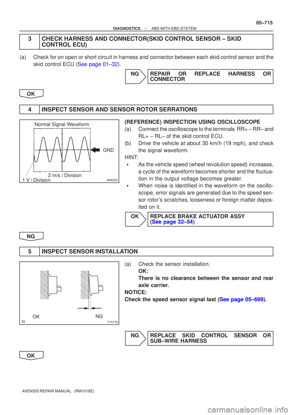
(REFERENCE) INSPECTION USING OSCILLOSCOPE
(a)Connect the oscilloscope to the terminals RR+ ± RR± and RL+ ± RL± of the skid control ECU.
(b)Drive the vehicle at about 30 km/h (19 mph), and check the signal waveform.
HINT:
�As the vehicle speed (wheel revolution speed) increases,
a cycle of the waveform becomes shorter and the fluctua-
tion in the output voltage becomes greater.
�When noise is identified in the waveform on the oscillo-
scope, error signals are generated due to the speed sen-
sor rotor's scratches, looseness or foreign matter depos-
ited on it.
OKREPLACE BRAKE ACTUATOR ASSY (See page 32±54)
NG
5 INSPECT SENSOR INSTALLATION
(a) Check the sensor installation. OK:
There is no clearance between the sensor and rear
axle carrier.
NOTICE:
Check the speed sensor signal last (See page 05±699).
NG REPLACE SKID CONTROL SENSOR OR SUB±WIRE HARNESS
OK
Page 794 of 5135
W04846
05±716
±
DIAGNOSTICS ABS WITH EBD SYSTEM
AVENSIS REPAIR MANUAL (RM1018E)
6INSPECT SPEED SENSOR TIP
(a)Remove the skid control sensor (See page 32±61).
(b)Check the sensor tip. OK:
No scratches or foreign objects on the sensor tip. NOTICE:
Check the speed sensor signal last (See page 05±699).
NGCLEAN OR REPAIR SKID CONTORL SENSOR
OK
7INSPECT SENSOR ROTOR
(a)Check the sensor rotor serrations. OK:
No scratches, missing teeth or foreign objects.
NOTICE:
Check the speed sensor signal last (See page 05±699).
NGREPLACE REAR AXLE HUB & BEARING ASSY RH
NGREPLACE REAR AXLE HUB & BEARING ASSY LH
OK
REPLACE BRAKE ACTUATOR ASSY(See page 32±54)
Page 795 of 5135

BR3583
BR3582F00010
Rotor
+VSpeed Sensor
MagnetCoilNS
To ECU
Low Speed
High Speed
±V
± DIAGNOSTICSABS WITH EBD SYSTEM
05±709
AVENSIS REPAIR MANUAL (RM1018E)
DTC C0200/31 RIGHT FRONT SPEED SENSOR
DTC C0205/32 LEFT FRONT SPEED SENSOR
DTC C1330/35 RIGHT FRONT SPEED SENSOR CIRCUIT
DTC C1331/36 LEFT FRONT SPEED SENSOR CIRCUIT
CIRCUIT DESCRIPTION
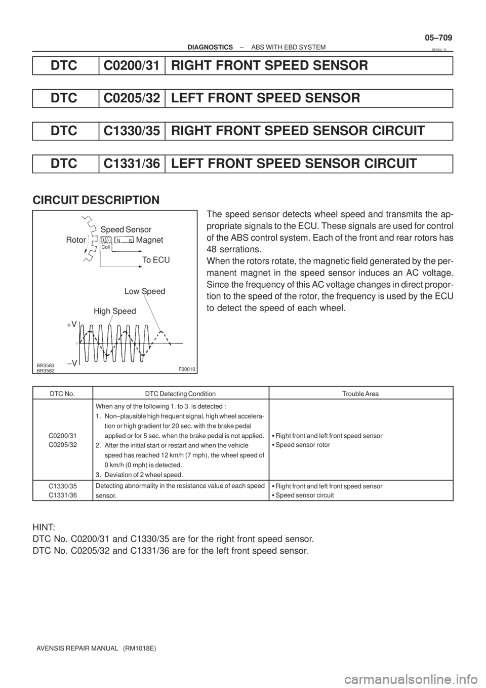
The speed sensor detects wheel speed and transmits the ap-
propriate signals to the ECU. These signals are used for control
of the ABS control system. Each of the front and rear rotors has
48 serrations.
When the rotors rotate, the magnetic field generated by the per-
manent magnet in the speed sensor induces an AC voltage.
Since the frequency of this AC voltage changes in direct propor-
tion to the speed of the rotor, the frequency is used by the ECU
to detect the speed of each wheel.
DTC No.DTC Detecting ConditionTrouble Area
C0200/31
C0205/32
When any of the following 1. to 3. is detected :
1. Non±plausible high frequent signal, high wheel accelera-
tion or high gradient for 20 sec. with the brake pedal
applied or for 5 sec. when the brake pedal is not applied.
2. After the initial start or restart and when the vehicle
speed has reached 12 km/h (7 mph), the wheel speed of
0 km/h (0 mph) is detected.
3. Deviation of 2 wheel speed.
�Right front and left front speed sensor
�Speed sensor rotor
C1330/35
C1331/36Detecting abnormality in the resistance value of each speed
sensor.�Right front and left front speed sensor
�Speed sensor circuit
HINT:
DTC No. C0200/31 and C1330/35 are for the right front speed sensor.
DTC No. C0205/32 and C1331/36 are for the left front speed sensor.
050XJ±11