Page 4520 of 5135
![TOYOTA AVENSIS 2005 Service Repair Manual G31161
THO
E2 BRE12
28 32
7 E1
Electronically Controlled
Transmission Solenoid
E13 O
1
OVECM
E2 THO5V 05−574
− DIAGNOSTICSELECTRONIC CONTROLLED AUTOMATIC
TRANSAXLE [ECT] (U151E)
AVENSIS Supplement TOYOTA AVENSIS 2005 Service Repair Manual G31161
THO
E2 BRE12
28 32
7 E1
Electronically Controlled
Transmission Solenoid
E13 O
1
OVECM
E2 THO5V 05−574
− DIAGNOSTICSELECTRONIC CONTROLLED AUTOMATIC
TRANSAXLE [ECT] (U151E)
AVENSIS Supplement](/manual-img/14/57441/w960_57441-4519.png)
G31161
THO
E2 BRE12
28 32
7 E1
Electronically Controlled
Transmission Solenoid
E13 O
1
OVECM
E2 THO5V 05−574
− DIAGNOSTICSELECTRONIC CONTROLLED AUTOMATIC
TRANSAXLE [ECT] (U151E)
AVENSIS Supplement (RM1045E)
DTC P0711TRANSMISSION FLUID TEMPERATURE
SENSOR ”A” PERFORMANCE
CIRCUIT DESCRIPTION
The ATF (Automatic Transmission Fluid) temperature sensor converts the fluid temperature into a resistance
value which is input into the ECM.
DTC No.DTC Detection ConditionTrouble Area
P0711
(A) Both (a) and (b) are detected: (2−trip detection logic)
(a) Intake air and engine coolant temperatures are more than
−10˚C (14_F) at engine start
(b) After normal driving for over 19 min. and 8 km (5 mile) or
more, ATF temp. is less than 10˚C (50_F)
(B) When engine coolant temp. is less than 35˚C (95_F) at
engine start, the ATF temp. is 110˚C (230_F) or more after
17 min. of engine start (2−trip detection logic).
SOpen or short in ATF temperature sensor circuit
STransmission wire (ATF temperature sensor)
SECM
MONITOR DESCRIPTION
The ATF temperature sensor converts the ATF temperature to an electrical resistance value. Based on the
resistance, the ECM determines the ATF temperature and detects an opens or shorts in the ATF temperature
circuit or a fault of the ATF temperature sensor.
After running the vehicle for a certain period, the ATF temperature should increase. If the ATF temperature
is below 10_C (50_F) after running the vehicle for a certain period, the ECM interprets this as a fault, and
turns on the MIL.
When the ATF temperature is 110_C (230_F) or more after 17 minutes of engine cold start, the ECM also
determines this as a fault, turns on the MIL, and stores the DTC.
WIRING DIAGRAM
05JLG−01
Page 4524 of 5135
![TOYOTA AVENSIS 2005 Service Repair Manual G31161
THO
E2 BRE12
28 32
7 E1
Electronically Controlled
Transmission Solenoid
E13 O
1
OVECM
E2 THO5V 05−572
− DIAGNOSTICSELECTRONIC CONTROLLED AUTOMATIC
TRANSAXLE [ECT] (U151E)
AVENSIS Supplement TOYOTA AVENSIS 2005 Service Repair Manual G31161
THO
E2 BRE12
28 32
7 E1
Electronically Controlled
Transmission Solenoid
E13 O
1
OVECM
E2 THO5V 05−572
− DIAGNOSTICSELECTRONIC CONTROLLED AUTOMATIC
TRANSAXLE [ECT] (U151E)
AVENSIS Supplement](/manual-img/14/57441/w960_57441-4523.png)
G31161
THO
E2 BRE12
28 32
7 E1
Electronically Controlled
Transmission Solenoid
E13 O
1
OVECM
E2 THO5V 05−572
− DIAGNOSTICSELECTRONIC CONTROLLED AUTOMATIC
TRANSAXLE [ECT] (U151E)
AVENSIS Supplement (RM1045E)
WIRING DIAGRAM
INSPECTION PROCEDURE
HINT:
According to the DATA LIST displayed by the hand−held tester, you can read the value of the switch, sensor,
actuator and so on without parts removal. Reading the DATA LIST as the first step of troubleshooting is one
method to shorten labor time.
(a) Warm up the engine.
(b) Turn the ignition switch off.
(c) Connect the hand−held tester to the DLC3.
(d) Turn the ignition switch to the ON position.
(e) Push the ”ON” button of the hand−held tester.
(f) Select the item ”DIAGNOSIS / OBD/MOBD / DATA LIST”.
(g) According to the display on tester, read the ”DATA LIST”.
ItemMeasurement Item/
Range (display)Normal Condition
AT FLUID TEMP
ATF Temp. Sensor Value/
min.:−40_C(−40_F)
max.: 215_C(419_F)
Approx. 80_C(176_F) (After Stall Test)
HINT:
When DTC P0712 is output and hand−held tester output is150_C (302_F), there is a short circuit.
When DTC P0713 is output and hand−held tester output is−40_C(−40_F), there is an open circuit.
Measure the resistance between terminal THO1(THO) and body ground.
Temperature DisplayedMalfunction
−40˚C(−40˚F)Open circuit
150˚C(302˚F) or moreShort circuit
Page 4527 of 5135
G30839
E9
N
D 6ECM
E10
E9
E10
E13
E10
E10
E10P
R
STA
SPT1
SFTD
SFTU W−L
J5 J/C
R−Y
CC
J/C
J23C A IK220
5
R W−L
R−Y 1 PL
RL
NL
DL
6 75 RBIK1
IK1 1
R−W
J/C
J13J12 BB
B−W
Fuse Block
66
21 ST
B−Y
Center J/B
CG
CDCA
CA87
1 1
I13 Ignition SW
AM2 ST2
AM1IG1 4
3
1G−Y
G−R
B−RDHDHDN DA DB
DA
AM12 13 5IG1Relay GAUGE2 GAUGE1
1 277
5
1Driver Side J/B
11
IE4IP1 3
IG S
SFTD
SFTU
E52 R−WT7 Transmission Control SW
L
B
R
J17
J/CA
A
B−R
11A
Engine Room J/B No.4AM2
2
1
B−G
W−B
J15 J/C
W−B
IP A IK IJ
4B 4A1
1 1 2ALT
1
4D
Battery
B−G
FL MAIN
*1: LHD *2: RHD(*1) R−Y(*1)
J22 2
R
LG−B
B−Y
A IK2
IK2 R−W
9
10
LG−B
B−Y
A J12 J/C
B−W
9
7
1
W−B
(*1) (*2)
1
W−B
(*1)
(*2) B−G
911
7
10
17
20
21
22
Engine Room R/B and J/B No.1
R−Y
(*2)R−Y
(*2) N1
Neutral Start SW
3
R−W
R−W
− DIAGNOSTICSELECTRONIC CONTROLLED AUTOMATIC
TRANSAXLE [ECT] (U151E)05−567
AVENSIS Supplement (RM1045E)
WIRING DIAGRAM
Page 4548 of 5135
G31593
Warmed up
sufficiently
Approx.100 km/h
(62 mph)
Vehicle Speed
Approx. 80 km/h
(50 mph)
0
Normal acceleration
through all the gears from1st to 5th
Lock−up ON
Vehicle Speed
Stop
(Idling)
Maintain a constant speed or gradual acceleration (with the throttle open)
for 3 minutes or more.
*1 05−544
− DIAGNOSTICSELECTRONIC CONTROLLED AUTOMATIC
TRANSAXLE [ECT] (U151E)
AVENSIS Supplement (RM1045E)
HINT:
*1: Drive at such a speed in the uppermost gear, to engage lock−up. The vehicle can be driven at a speed
lower than that in the above diagram under the lock−up condition.
NOTICE:
It is necessary to drive the vehicle for approximately 30 minutes to detect DTC P0711(ATF tempera-
ture sensor malfunction).
Page 4911 of 5135

05–106
–
DIAGNOSTICS SFI SYSTEM (1ZZ–FE/3ZZ–FE)(From February, 2004)
AVENSIS REPAIR MANUAL SUPPLEMENT
(RM1098E)
DTC P0171 SYSTEM TOO LEAN (BANK 1)
DTC P0172 SYSTEM TOO RICH (BANK 1)
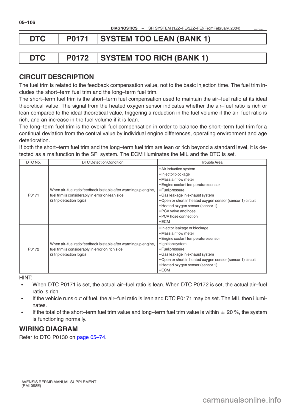
CIRCUIT DESCRIPTION
The fuel trim is related to the feedback compensation value, not to the bas\
ic injection time. The fuel trim in-
cludes the short–term fuel trim and the long–term fuel trim.
The short–term fuel trim is the short–term fuel compensation used to \
maintain the air–fuel ratio at its ideal
theoretical value. The signal from the heated oxygen sensor indicates whether the air–fuel r\
atio is rich or
lean compared to the ideal theoretical value, triggering a reduction in the \
fuel volume if the air–fuel ratio is
rich, and an increase in the fuel volume if it is lean.
The long–term fuel trim is the overall fuel compensation in order to bal\
ance the short–term fuel trim for a
continual deviation from the central value by individual engine differences, operating environment and age
deterioration.
If both the short–term fuel trim and the long–term fuel trim are l\
ean or rich beyond a standard level, it is de-
tected as a malfunction in the SFI system. The ECM illuminates the MIL and the\
DTC is set.
DTC No.DTC Detection ConditionTrouble Area
P0171
When air–fuel ratio feedback is stable after warming up engine,
fuel trim is considerably in error on lean side
(2 trip detection logic)
� Air induction system
� Injector blockage
� Mass air flow meter
� Engine coolant temperature sensor
� Fuel pressure
� Gas leakage in exhaust system
� Open or short in heated oxygen sensor (sensor 1) circuit
� Heated oxygen sensor (sensor 1)
� PCV valve and hose
� PCV hose connection
� ECM
P0172
When air–fuel ratio feedback is stable after warming up engine,
fuel trim is considerably in error on rich side
(2 trip detection logic)
�Injector leakage or blockage
� Mass air flow meter
� Engine coolant temperature sensor
� Ignition system
� Fuel pressure
� Gas leakage in exhaust system
� Open or short in heated oxygen sensor (sensor 1) circuit
� Heated oxygen sensor (sensor 1)
� ECM
HINT:
�When DTC P0171 is set, the actual air–fuel ratio is lean. When DTC P0172 is set, the actual air–fuel\
ratio is rich.
�If the vehicle runs out of fuel, the air–fuel ratio is lean and DTC P01\
71 may be set. The MIL then illumi-
nates.
�If the total of the short–term fuel trim value and long–term fuel trim value is within � 20 %, the system
is functioning normally.
WIRING DIAGRAM
Refer to DTC P0130 on page 05–74.
05KO5–02
Page 4919 of 5135

A79114
Wire Harness Side:
Sensor 1H7
Heated Oxygen Sensor Connector
HT
OX
E1
Front View
A65746
HT1A
ECM Connector E12
OX1AE2 E13
A78602
Reference (Sensor 1 System Diagram):
Heated Oxygen Sensor
EFI Relay
Heater
Sensor
OX1A HT1AECM
From
Battery
EFI Fuse
E2
MREL OX HT
E1 +B
05–114
– DIAGNOSTICSSFI SYSTEM (1ZZ–FE/3ZZ–FE)(From February, 2004)
AVENSIS REPAIR MANUAL SUPPLEMENT
(RM1098E)
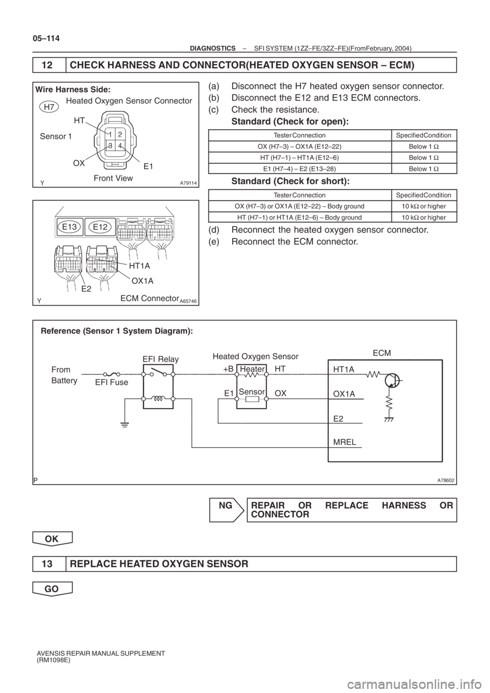
12 CHECK HARNESS AND CONNECTOR(HEATED OXYGEN SENSOR – ECM)
(a) Disconnect the H7 heated oxygen sensor connector.
(b) Disconnect the E12 and E13 ECM connectors.
(c) Check the resistance.
Standard (Check for open):
Tester ConnectionSpecified Condition
OX (H7–3) – OX1A (E12–22)Below 1 Ω
HT (H7–1) – HT1A (E12–6)Below 1 Ω
E1 (H7–4) – E2 (E13–28)Below 1 Ω
Standard (Check for short):
Tester ConnectionSpecified Condition
OX (H7–3) or OX1A (E12–22) – Body ground10 kΩ or higher
HT (H7–1) or HT1A (E12–6) – Body ground10 kΩ or higher
(d) Reconnect the heated oxygen sensor connector.
(e) Reconnect the ECM connector.
NG REPAIR OR REPLACE HARNESS OR
CONNECTOR
OK
13 REPLACE HEATED OXYGEN SENSOR
GO
Page 4923 of 5135

A78602
Reference (Sensor 2 System Diagram):Heated Oxygen Sensor
EFI Relay
Heater
Sensor OX1B
HT1BECM
From
Battery EFI Fuse
E2MREL
OX
HT
E1
+B
05–46
–
DIAGNOSTICS SFI SYSTEM (1ZZ–FE/3ZZ–FE)(From February, 2004)
AVENSIS REPAIR MANUAL SUPPLEMENT
(RM1098E)
DTC P0037 OXYGEN SENSOR HEATER CONTROL CIRCUIT LOW (BANK 1 SENSOR 2)
DTC P0038 OXYGEN SENSOR HEATER CONTROL CIRCUIT HIGH (BANK 1 SENSOR 2)
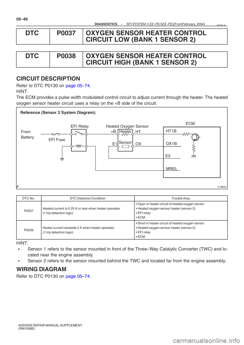
CIRCUIT DESCRIPTION
Refer to DTC P0130 on page 05–74.
HINT:
The ECM provides a pulse width modulated control circuit to adjust current \
through the heater. The heated
oxygen sensor heater circuit uses a relay on the +B side of the circuit.
DTC No.DTC Detection ConditionTrouble Area
P0037Heated current is 0.25 A or less when heater operates
(1 trip detection logic)
� Open in heater circuit of heated oxygen sensor
� Heated oxygen sensor heater (sensor 2)
� EFI relay
� ECM
P0038Heater current exceeds 2 A when heater operates
(1 trip detection logic)
�Short in heater circuit of heated oxygen sensor
� Heated oxygen sensor heater (sensor 2)
� EFI relay
� ECM
HINT:
�Sensor 1 refers to the sensor mounted in front of the Three–Way Catalytic Converter (TWC) and lo-
cated near the engine assembly.
�Sensor 2 refers to the sensor mounted behind the TWC and located far fro\
m the engine assembly.
WIRING DIAGRAM
Refer to DTC P0130 on page 05–74.
05KNW–02
Page 4926 of 5135

A78602
EFI RelayHeater
Sensor OX1A
HT1AECM
From
Battery EFI Fuse
E2
MREL
Reference (Sensor 1 System Diagram):
Heated Oxygen Sensor
OX
HT
E1
+B
–
DIAGNOSTICS SFI SYSTEM (1ZZ–FE/3ZZ–FE)(From February, 2004)
05–43
AVENSIS REPAIR MANUAL SUPPLEMENT
(RM1098E)
DTC P0031 OXYGEN SENSOR HEATER CONTROL
CIRCUIT LOW (BANK 1 SENSOR 1)
DTC P0032 OXYGEN SENSOR HEATER CONTROL CIRCUIT HIGH (BANK 1 SENSOR 1)
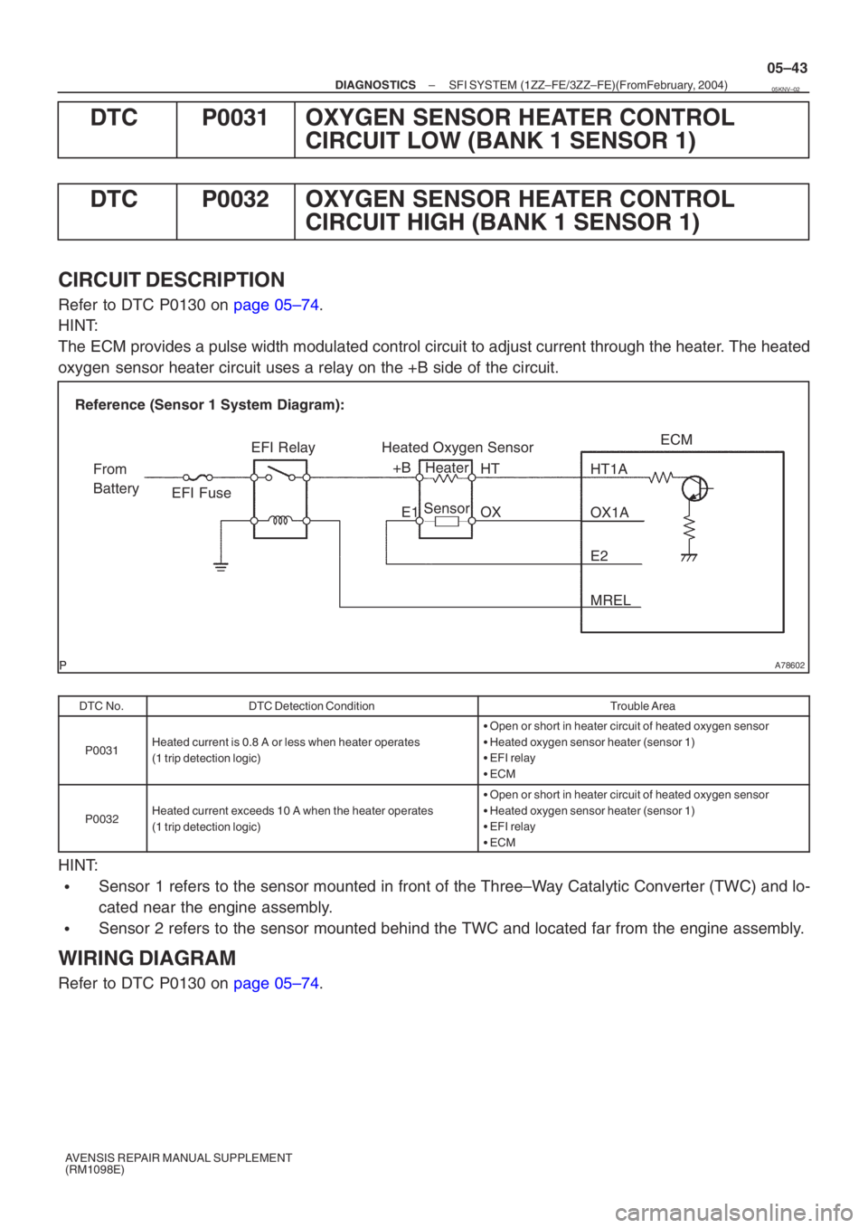
CIRCUIT DESCRIPTION
Refer to DTC P0130 on page 05–74.
HINT:
The ECM provides a pulse width modulated control circuit to adjust current \
through the heater. The heated
oxygen sensor heater circuit uses a relay on the +B side of the circuit.
DTC No.DTC Detection ConditionTrouble Area
P0031Heated current is 0.8 A or less when heater operates
(1 trip detection logic)
� Open or short in heater circuit of heated oxygen sensor
� Heated oxygen sensor heater (sensor 1)
� EFI relay
� ECM
P0032Heated current exceeds 10 A when the heater operates
(1 trip detection logic)
�Open or short in heater circuit of heated oxygen sensor
� Heated oxygen sensor heater (sensor 1)
� EFI relay
� ECM
HINT:
�Sensor 1 refers to the sensor mounted in front of the Three–Way Catalytic Converter (TWC) and lo-
cated near the engine assembly.
�Sensor 2 refers to the sensor mounted behind the TWC and located far fro\
m the engine assembly.
WIRING DIAGRAM
Refer to DTC P0130 on page 05–74.
05KNV–02