Page 4961 of 5135
A96006
2
EFI
1 1
FL MAINW–BEFI Relay
1 43 5
2
EA1
B–W
V5
EVAP VSV
219
E12
MREL 4
E10 44
44
42 1
B–W
W–G 1 IE1 2
GR13
EC 1 1A
4A
4B1
1
B–G
BatteryB–W
EFI
No. 2 B–Y
B–G
EVP1ECM
Engine
Room
R/B No.1Engine
Room
R/B No.4 Engine Room R/B No.4
GR
– DIAGNOSTICSSFI SYSTEM (1ZZ–FE/3ZZ–FE)(From February, 2004)
05–155
AVENSIS REPAIR MANUAL SUPPLEMENT
(RM1098E)
DTC P0443 EVAPORATIVE EMISSION CONTROL
SYSTEM PURGE CONTROL VALVE CIRCUIT
CIRCUIT DESCRIPTION
In order to reduce hydrocarbon (HC) emissions, evaporated fuel from the fuel tank is routed through the char-
coal canister to the intake manifold for combustion in the cylinders.
The ECM changes the duty signal to the EVAP VSV so that the intake of HC emissions is appropriate for
the driving conditions (engine load, engine speed, vehicle speed, etc.) after the engine is warmed up.
DTC No.DTC Detection ConditionTrouble Area
P0443Proper response to ECM command does not occur (1 trip
detection logic)�Open or short in EVAP VSV circuit
�EVAP VSV
�ECM
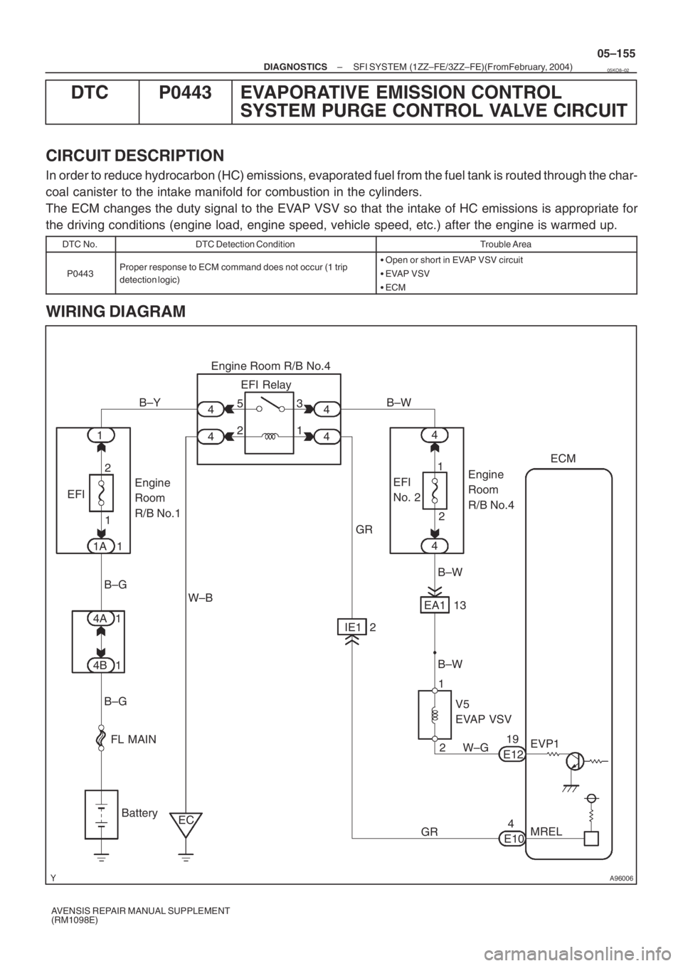
WIRING DIAGRAM
05KO8–02
Page 4966 of 5135
05–152
–
DIAGNOSTICS SFI SYSTEM (1ZZ–FE/3ZZ–FE)(From February, 2004)
AVENSIS REPAIR MANUAL SUPPLEMENT
(RM1098E)
NOTICE:
If the conditions in this test are not strictly followed, no malfunction\
will be detected. If you do not
have the intelligent tester II, turn the ignition switch to OFF after perfor\
ming steps from (d) to (i), then
perform steps (d) to (i) again.
WIRING DIAGRAM
Refer to DTC P0130 on page 05–74.
INSPECTION PROCEDURE
HINT:
Read freeze frame data using the intelligent tester II. Freeze frame data record the engine condition\
when
malfunctions are detected. When troubleshooting, freeze frame data can h\
elp determine if the vehicle was
moving or stationary, if the engine was warmed up or not, if the air–fuel ratio was lean \
or rich, and other data
from the time the malfunction occurred.
1 CHECK OTHER DTC OUTPUT(IN ADDITION TO DTC P0420)
(a) Connect the intelligent tester II to the DLC3.
(b) Turn the ignition switch to ON and turn the intelligent tester ll ON.
(c) Select the following menu items: Powertrain / Engine and ECT / DTC.
(d) Read DTCs.
Result:
Display (DTC Output)Proceed To
P0420A
P0420 and other DTCsB
HINT:
If any DTCs other than P0420 are output, troubleshoot those DTCs first.
B GO TO RELEVANT DTC CHART (See page 05–27 )
A
2 CHECK FOR EXHAUST GAS LEAKAGE
OK: No gas leakage. NG REPAIR OR REPLACE EXHAUST GASLEAKAGE POINT
OK
3 INSPECT HEATED OXYGEN SENSOR(SENSOR 1) ( See page 05–74)
NG REPLACE HEATED OXYGEN SENSOR
OK
Page 4969 of 5135
A63955
GND
CH1
(G2+)
CH2
(NE+) GND
05–140
–
DIAGNOSTICS SFI SYSTEM (1ZZ–FE/3ZZ–FE)(From February, 2004)
AVENSIS REPAIR MANUAL SUPPLEMENT
(RM1098E)
DTC P0340 CAMSHAFT POSITION SENSOR ”A” CIRCUIT (BANK 1 OR SINGLE SENSOR)
DTC P0341 CAMSHAFT POSITION SENSOR ”A” CIRCUIT RANGE/PERFORMANCE (BANK 1
OR SINGLE SENSOR)
CIRCUIT DESCRIPTION
The Camshaft Position (CMP) sensor consists of a magnet and an iron core which is wrapped with coppe\
r
wire, and is installed on the cylinder head. When the camshaft rotates, each \
of 3 teeth on the camshaft
passes through the CMP sensor. This activates the internal magnet in the sensor, generating a voltage in
the copper wire. The camshaft rotation is synchronized with the crankshaft rotation. When the crankshaft
turns twice the voltage is generated 3 times in the CMP sensor. The generated voltage in the sensor acts
as a signal, allowing the ECM to locate the camshaft position. This signal is then used to con\
trol ignition tim-
ing, fuel injection timing, and the VVT system.
DTC No.DTC Detection ConditionTrouble Area
P0340
�No camshaft position sensor signal to ECM during cranking
(2 trip detection logic)�Open or short in camshaft position sensor circuit
� Camshaft position sensor
�Camshaft timing pulleyP0340(2 trip detection logic)
�No camshaft position sensor signal to ECM at engine speed
of 600 rpm or more (1 trip detection logic)�Camshaft timing pulley
� Jumped tooth of timing chain
� ECM
P0341While crankshaft rotates twice, camshaft position sensor signal
is input to ECM 12 times or more (1 trip detection logic)
�Open or short in camshaft position sensor circuit
� Camshaft position sensor
� Camshaft timing pulley
� Jumped tooth of timing chain
� ECM
HINT:
�DTC P0340 indicates a malfunction related to the CMP sensor (+) circuit (the wi\
re harness between
the ECM and CMP sensor, and the CMP sensor itself).
�DTC P0341 indicates a malfunction related to the CMP sensor (–) cir\
cuit (the wire harness between
the ECM and CMP sensor, and the CMP sensor itself).
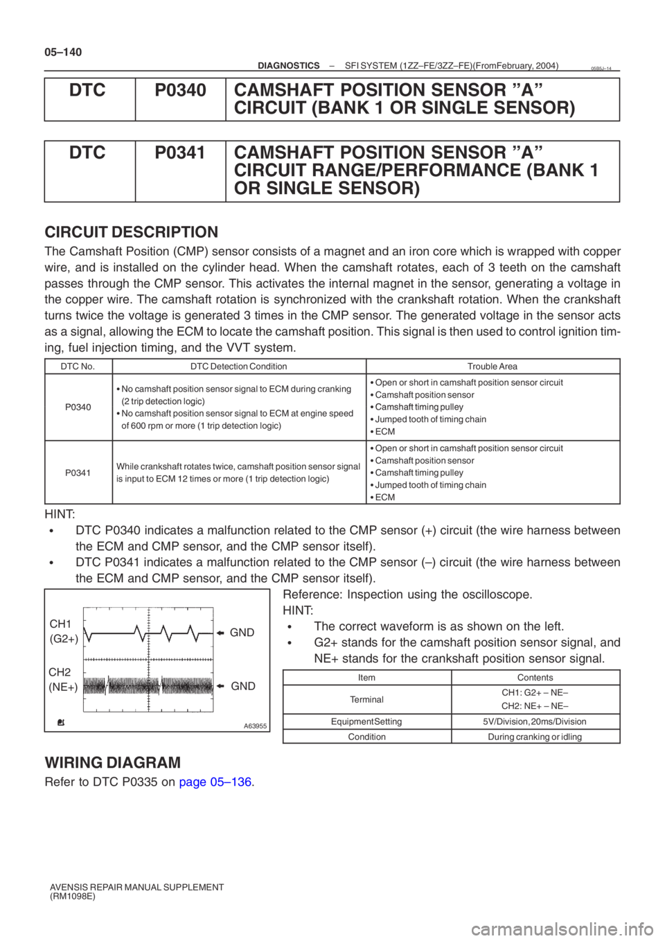
Reference: Inspection using the oscilloscope.
HINT:
�The correct waveform is as shown on the left.
�G2+ stands for the camshaft position sensor signal, and
NE+ stands for the crankshaft position sensor signal.
ItemContents
TerminalCH1: G2+ – NE–
CH2: NE+ – NE–
Equipment Setting5V/Division, 20ms/Division
ConditionDuring cranking or idling
WIRING DIAGRAM
Refer to DTC P0335 on page 05–136.
05B5J–14
Page 4973 of 5135
A96003
K1
Knock Sensor1 (Shielded)
J/C J5
J51
E12 ECM
KNK1
EH
2
E122
EKNK
BB
J65 V
W
J6
EE D
EB1
EB1
2
1
D
BR BR
W
–
DIAGNOSTICS SFI SYSTEM (1ZZ–FE/3ZZ–FE)(From February, 2004)
05–133
AVENSIS REPAIR MANUAL SUPPLEMENT
(RM1098E)
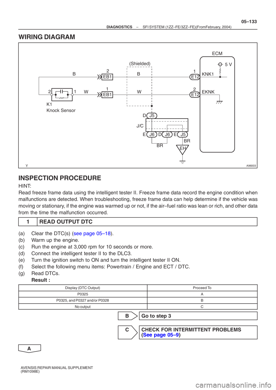
WIRING DIAGRAM
INSPECTION PROCEDURE
HINT:
Read freeze frame data using the intelligent tester II. Freeze frame data record the engine condition\
when
malfunctions are detected. When troubleshooting, freeze frame data can h\
elp determine if the vehicle was
moving or stationary, if the engine was warmed up or not, if the air–fuel ratio was lean \
or rich, and other data
from the time the malfunction occurred.
1 READ OUTPUT DTC
(a) Clear the DTC(s) ( see page 05–18).
(b) Warm up the engine.
(c) Run the engine at 3,000 rpm for 10 seconds or more.
(d) Connect the intelligent tester II to the DLC3.
(e) Turn the ignition switch to ON and turn the intelligent tester II ON.
(f) Select the following menu items: Powertrain / Engine and ECT / DTC.
(g) Read DTCs. Result :
Display (DTC Output)Proceed To
P0325A
P0325, and P0327 and/or P0328B
No outputC
B Go to step 3
C CHECK FOR INTERMITTENT PROBLEMS (See page 05–9 )
A
Page 4978 of 5135
A76891
I13
Ignition Switch
4 6
B–R B–R
IE4 (LHD)
1
1 IP1
(RHD) DH
2
DL 16
Driver
Side J/B
IGN
B–R
1 AM2 IG2
1
2
2
1
1A1 1Engine
Room
R/B No.1
Engine
Room
J/B No.1
B–G
4A
1
4B1 Engine
Room
J/B No.4 B–R 2R–B 1
I5
Injector No.1
B–R
Y
W
B 1
#10
E13
2 #20
E13
#30
3
E13
4 #40
E13
7 E01
E13
E02
6
E13
W–B
W–B ECM
R–B R–B
R–B
R–B
R–B 21
I6
Injector No.2
21
I7
Injector No.3
21
I8
Injector No.4
EA18
4
13
25 IG2
Relay
B
W–B
B
EC EG
4
44 Engine
Room
R/B No.4
B–G
FL MAIN
Battery R–B
05–120
–
DIAGNOSTICS SFI SYSTEM (1ZZ–FE/3ZZ–FE)(From February, 2004)
AVENSIS REPAIR MANUAL SUPPLEMENT
(RM1098E)
WIRING DIAGRAM
Refer to DTC P0351 on page 05–143 for the wiring diagram of the ignition system.
Page 4998 of 5135
G31593
Warmed up
sufficiently
Approx.100 km/h
(62 mph)
Vehicle Speed
Approx. 80 km/h
(50 mph)
0
Lock–up ON
Vehicle Speed
Stop
(Idling)
Maintain a constant speed or gradual acceleration (with the throttle open)
for 3 minutes or more.
*1
Normal acceleration
through all the gears from 1st to 4th(O/D) 05–228
– DIAGNOSTICSELECTRONIC CONTROLLED AUTOMATIC
TRANSAXLE [ECT] (U341E) (From February, 2004)
AVENSIS REPAIR MANUAL SUPPLEMENT
(RM1098E)
HINT:
*1: Drive at such a speed in the uppermost gear, to engage lock–up. The vehicle can be driven at a speed
lower than that in the above diagram under the lock–up condition.
NOTICE:
It is necessary to drive the vehicle for approximately 30 minutes to detect DTC P0711 (ATF tempera-
ture sensor malfunction).
Page 5007 of 5135
05KAM–02
NE
THW
VTA1, 2
VC
SPD
STP
THONTS1
S2
SLT
SB
SL
W
SIL
TC ECMCrankshaft Position Sensor
Engine Coolant
Temperature Sensor
Throttle Position Sensor
Park/Neutral Position Switch
Speed Sensor
Skid Control ECU
Combination Meter
Input Turbine Speed Sensor
(Speed Sensor NT)
Stop Lamp Switch Assy
ATF (Automatic Transmission
Fluid) Temperature SensorShift Solenoid Valve S1
Shift Solenoid Valve S2
Shift Solenoid Valve SLT
MIL
(Malfunction Indicator Lamp)
DLC3
(Data Link Connector 3) Shift Solenoid Valve SB
Shift Solenoid Valve SL NSW
P, R, N, D
SFTU
SFTD Transmission Control Switch
(Transmission Floor Shift Assy)SPT
Kick Down SwitchKD
*1
*1: LHD
ST
Shift Solenoid Valve ST
– DIAGNOSTICSELECTRONIC CONTROLLED AUTOMATIC
TRANSAXLE [ECT] (U341E) (From February, 2004)05–213
AVENSIS REPAIR MANUAL SUPPLEMENT
(RM1098E)
SYSTEM DIAGRAM
The configuration of the electronic control system in the U341E automatic transaxles is as shown in the fol-
lowing chart.
Page 5021 of 5135
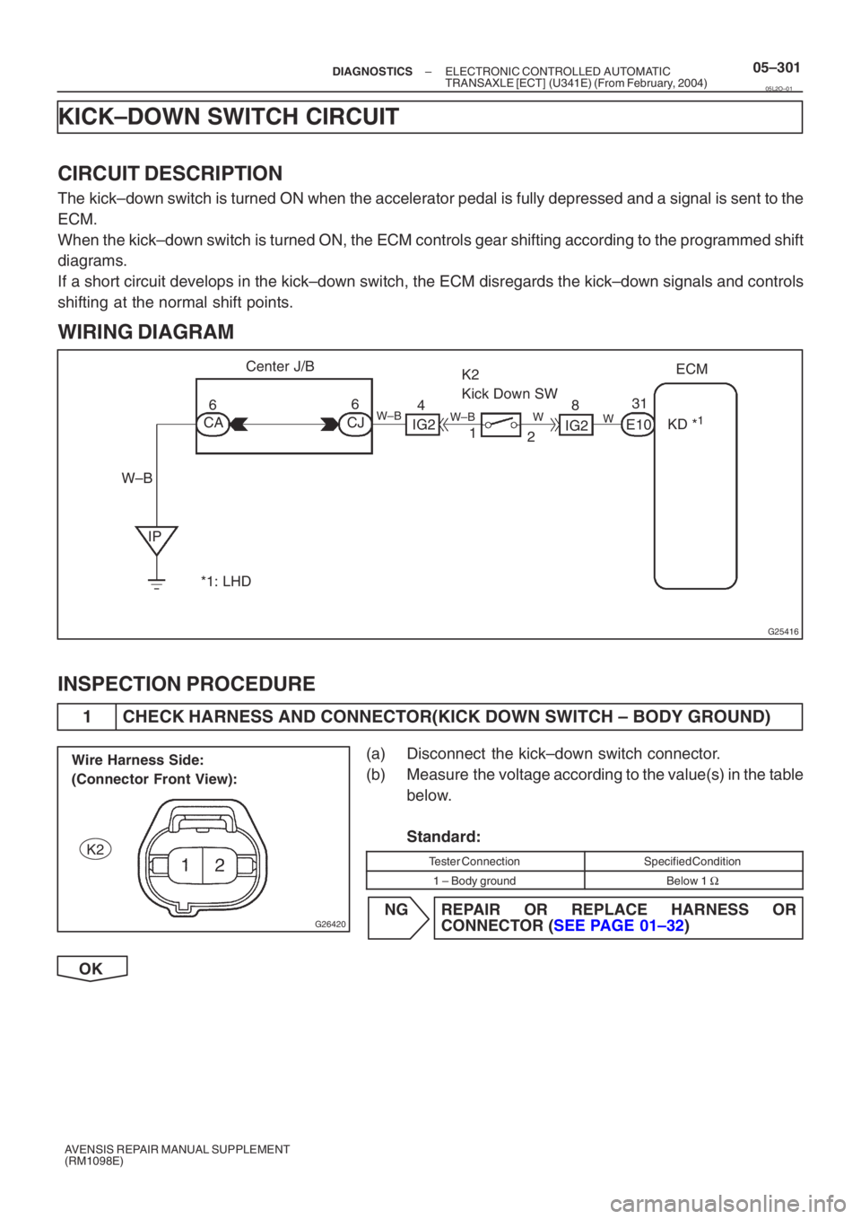
G25416
ECM
E10
K2
Kick Down SW
IP 6
6
CA 12
CJ
IG24
W–B Center J/B
31
8
IG2
W–B W
W
W–BKD *1
*1: LHD
G26420
Wire Harness Side:
(Connector Front View):
K2
–
DIAGNOSTICS ELECTRONIC CONTROLLED AUTOMATIC
TRANSAXLE [ECT] (U341E) (From February, 2004)05–301
AVENSIS REPAIR MANUAL SUPPLEMENT
(RM1098E)
KICK–DOWN SWITCH CIRCUIT
CIRCUIT DESCRIPTION
The kick–down switch is turned ON when the accelerator pedal is fully de\
pressed and a signal is sent to the
ECM.
When the kick–down switch is turned ON, the ECM controls gear shiftin\
g according to the programmed shift
diagrams.
If a short circuit develops in the kick–down switch, the ECM disregards\
the kick–down signals and controls
shifting at the normal shift points.
WIRING DIAGRAM
INSPECTION PROCEDURE
1 CHECK HARNESS AND CONNECTOR(KICK DOWN SWITCH – BODY GROUND)
(a) Disconnect the kick–down switch connector.
(b) Measure the voltage according to the value(s) in the table
below.
Standard:
Tester ConnectionSpecified Condition
1 – Body groundBelow 1 Ω
NG REPAIR OR REPLACE HARNESS OR
CONNEC TOR ( SEE PAGE 01–32 )
OK
05L2O–01