Page 2226 of 5135
141BL±01
A77339
A77343
No. 1 Cylinder TDC / CompressionIN
EX
14±186
±
ENGINE MECHANICAL VALVE CLEARANCE(1AZ±FSE)
AVENSIS REPAIR MANUAL (RM1018E)
VALVE CLEARANCE(1AZ±FSE)
ADJUSTMENT
1.DISCHARGE FUEL SYSTEM PRESSURE (See page 11±33)
2.REMOVE RADIATOR SUPPORT OPENING COVER
3.REMOVE ENGINE ROOM COVER SIDE
4.REMOVE ENGINE UNDER COVER RH 5.REMOVE ENGINE COVER SUB±ASSY NO.1
(a)Remove the 2 nuts and the engine cover No. 1.
6.REMOVE FUEL PRESSURE PULSATION DAMPER ASSY
7.REMOVE FUEL TUBE SUB±ASSY (See page 11±33)
8.REMOVE FUEL PIPE SUB±ASSY NO.1 (See page 11±52) SST 09023±12900
9. REMOVE IGNITION COIL ASSY
(a) Remove the 4 bolts and the ignition coils.
10.REMOVE CYLINDER HEAD COVER SUB±ASSY (See page 14±240)
11.SET NO. 1 CYLINDER TO TDC/COMPRESSION (See page 14±240)
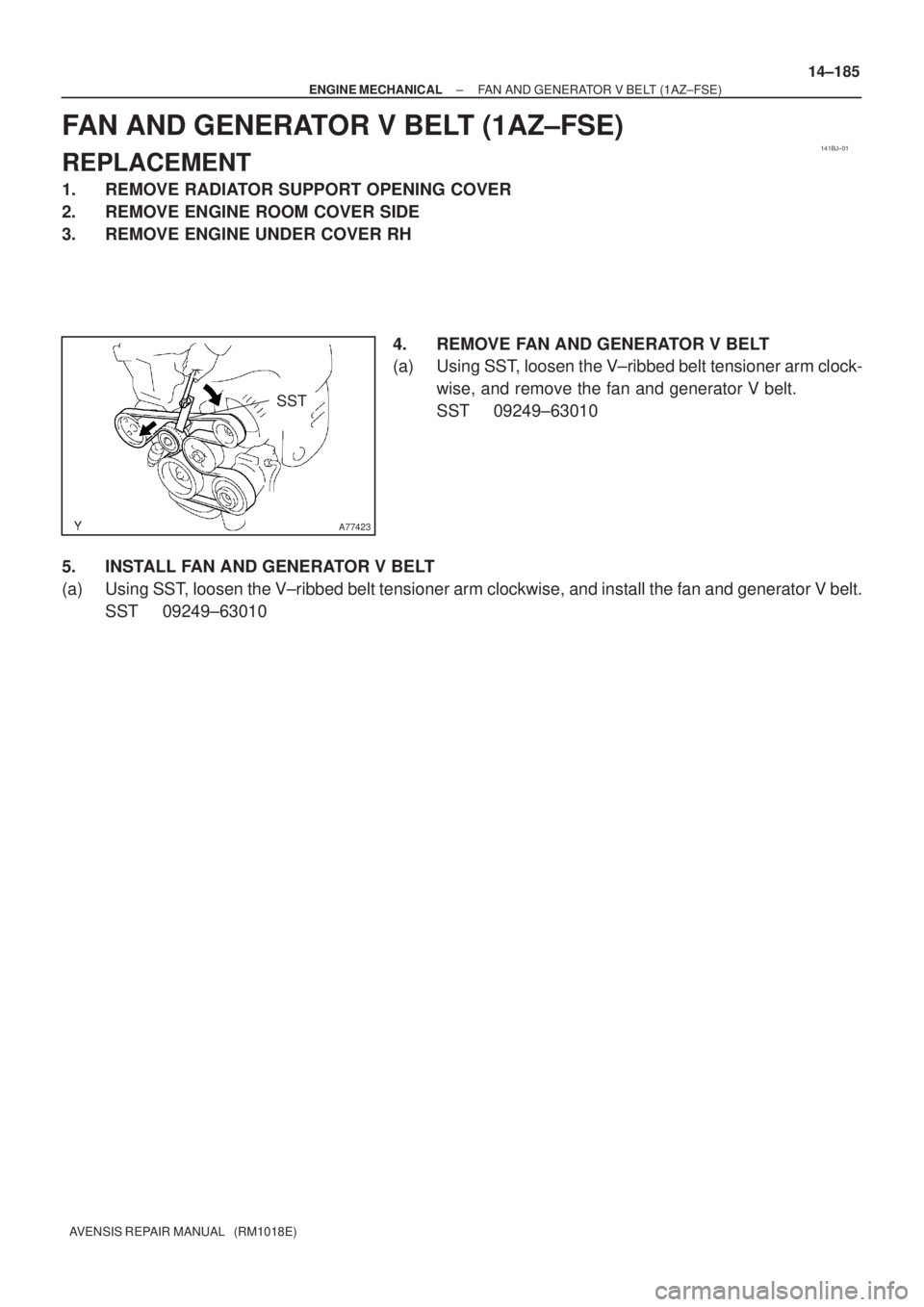
12. INSPECT VALVE CLEARANCE
HINT:
Inspect and adjust the valve clearance when the engine is cold.
(a) Check only the valve indicated in the illustration.(1) Using a feeler gauge, measure the clearance be-tween the valve lifter and the camshaft.
(2) Record the out±of specification valve clearance measurements. They will be used later to determine
the required replacement adjusting shim.
Valve clearance (Cold):
Intake 0.19 to 0.29 mm (0.0075 to 0.0114 in.)
Exhaust 0.30 to 0.40 mm (0.0118 to 0.0157 in.)
(b) Turn the crankshaft clockwise 1 revolution (360 �) and set
No. 4 cylinder to TDC/compression.
Page 2232 of 5135
141BJ±01
A77423
SST
± ENGINE MECHANICALFAN AND GENERATOR V BELT (1AZ±FSE)
14±185
AVENSIS REPAIR MANUAL (RM1018E)
FAN AND GENERATOR V BELT (1AZ±FSE)
REPLACEMENT
1. REMOVE RADIATOR SUPPORT OPENING COVER
2. REMOVE ENGINE ROOM COVER SIDE
3. REMOVE ENGINE UNDER COVER RH
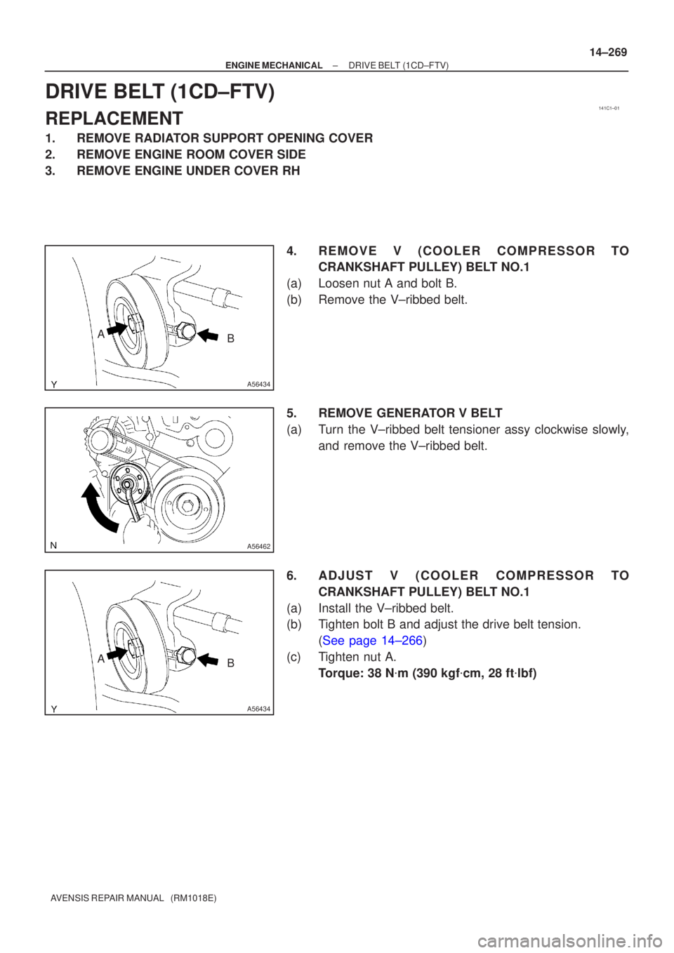
4. REMOVE FAN AND GENERATOR V BELT
(a) Using SST, loosen the V±ribbed belt tensioner arm clock-
wise, and remove the fan and generator V belt.
SST 09249±63010
5. INSTALL FAN AND GENERATOR V BELT
(a) Using SST, loosen the V±ribbed belt tensioner arm clockwise, and install the fan and generator V belt.
SST 09249±63010
Page 2249 of 5135
141C1±01
A56434
AB
A56462
A56434
AB
±
ENGINE MECHANICAL DRIVE BELT(1CD±FTV)
14±269
AVENSIS REPAIR MANUAL (RM1018E)
DRIVE BELT(1CD±FTV)
REPLACEMENT
1.REMOVE RADIATOR SUPPORT OPENING COVER
2.REMOVE ENGINE ROOM COVER SIDE
3.REMOVE ENGINE UNDER COVER RH
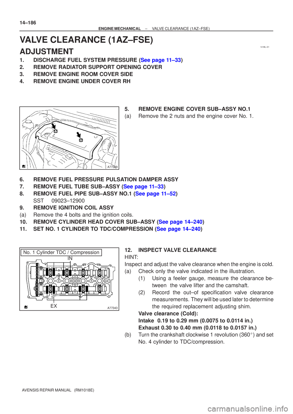
4.REMOVE V (COOLER CO MPRESSOR TO
CRANKSHAFT PULLEY) BELT NO.1
(a)Loosen nut A and bolt B.
(b)Remove the V±ribbed belt.
5.REMOVE GENERATOR V BELT
(a)Turn the V±ribbed belt tensioner assy clockwise slowly, and remove the V±ribbed belt.
6.ADJUS T V (COOLER CO MPRESSOR TO
CRANKSHAFT PULLEY) BELT NO.1
(a)Install the V±ribbed belt.
(b)Tighten bolt B and adjust the drive belt tension. (See page 14±266)
(c) Tighten nut A. Torque: 38 N �m (390 kgf �cm, 28 ft �lbf)
Page 2275 of 5135
A77309
15973
481062
A56228
A77413
Advance
Side Port
A31032
14±242
± ENGINE MECHANICALCAMSHAFT (1AZ±FSE)
AVENSIS REPAIR MANUAL (RM1018E)
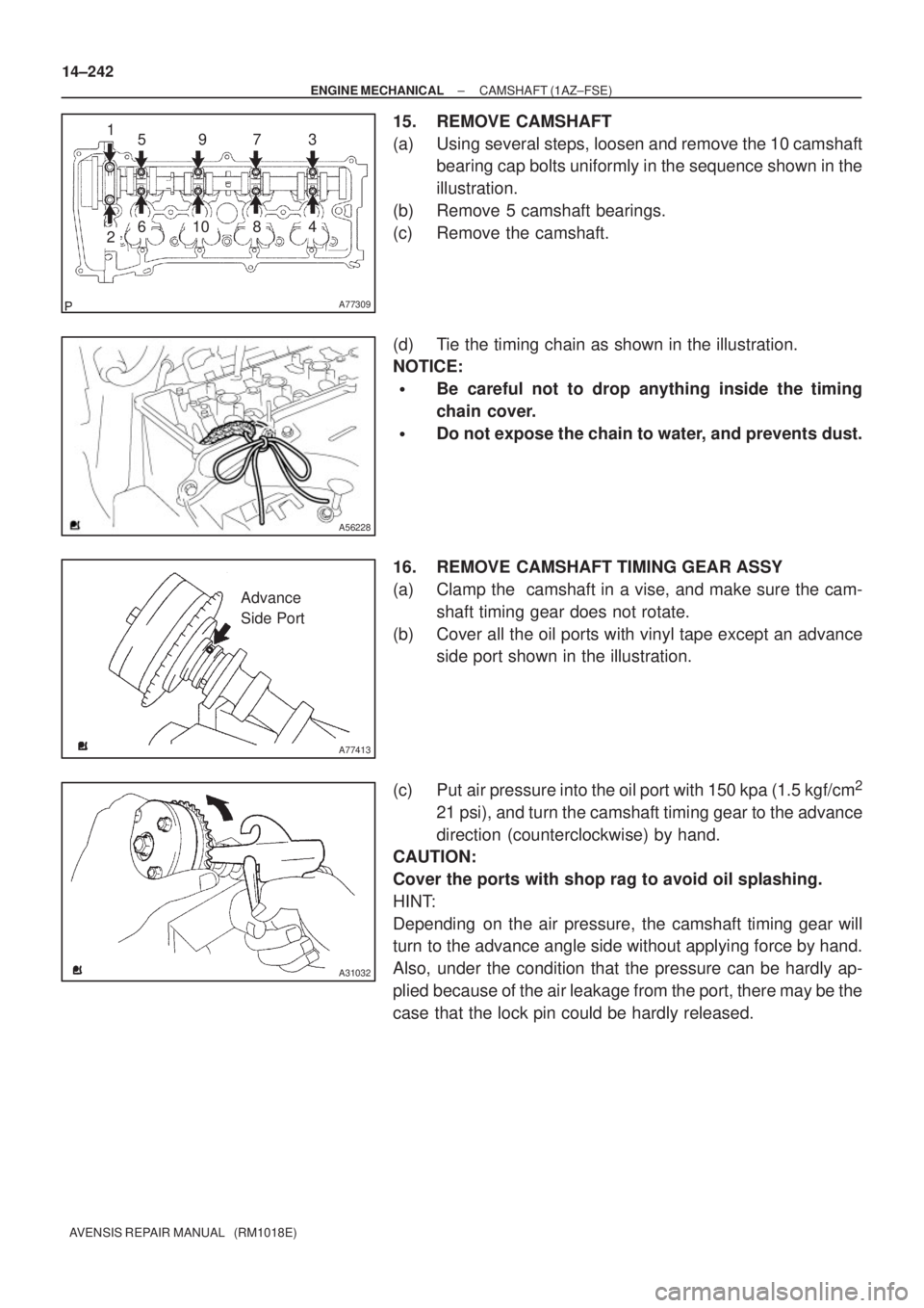
15. REMOVE CAMSHAFT
(a) Using several steps, loosen and remove the 10 camshaft
bearing cap bolts uniformly in the sequence shown in the
illustration.
(b) Remove 5 camshaft bearings.
(c) Remove the camshaft.
(d) Tie the timing chain as shown in the illustration.
NOTICE:
�Be careful not to drop anything inside the timing
chain cover.
�Do not expose the chain to water, and prevents dust.
16. REMOVE CAMSHAFT TIMING GEAR ASSY
(a) Clamp the camshaft in a vise, and make sure the cam-
shaft timing gear does not rotate.
(b) Cover all the oil ports with vinyl tape except an advance
side port shown in the illustration.
(c) Put air pressure into the oil port with 150 kpa (1.5 kgf/cm
2
21 psi), and turn the camshaft timing gear to the advance
direction (counterclockwise) by hand.
CAUTION:
Cover the ports with shop rag to avoid oil splashing.
HINT:
Depending on the air pressure, the camshaft timing gear will
turn to the advance angle side without applying force by hand.
Also, under the condition that the pressure can be hardly ap-
plied because of the air leakage from the port, there may be the
case that the lock pin could be hardly released.
Page 2278 of 5135
A77395
Engine
Front
A77396
HookPinTurn
Disconnect
A77397
Push Turn
Plunger
±
ENGINE MECHANICAL CAMSHAFT(1AZ±FSE)
14±245
AVENSIS REPAIR MANUAL (RM1018E)
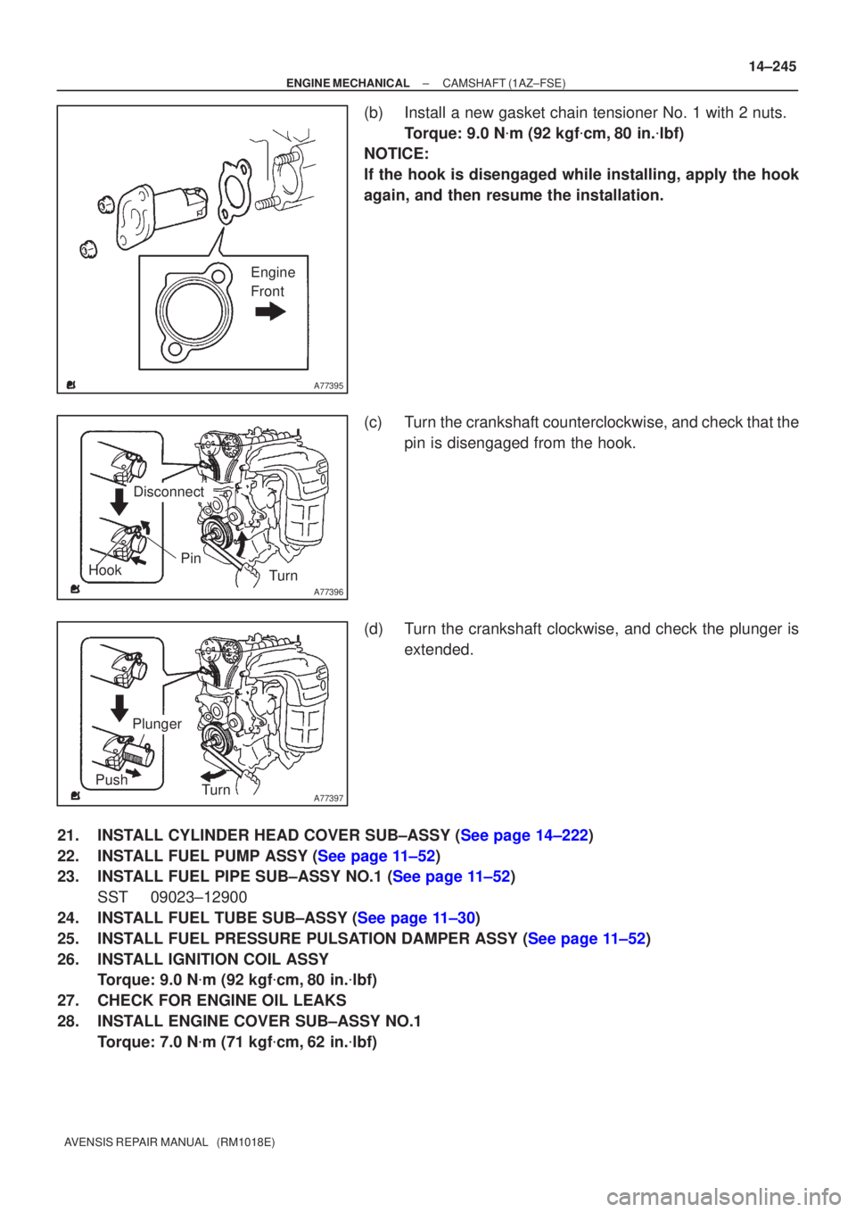
(b)Install a new gasket chain tensioner No. 1 with 2 nuts.
Torque: 9.0 N �m (92 kgf �cm,80 in. �lbf)
NOTICE:
If the hook is disengaged while installing, apply the hook
again, and then resume the installation.
(c)Turn the crankshaft counterclockwise, and check that the
pin is disengaged from the hook.
(d)Turn the crankshaft clockwise, and check the plunger is extended.
21.INSTALL CYLINDER HEAD COVER SUB±ASSY (See page 14±222)
22.INSTALL FUEL PUMP ASSY (See page 11±52)
23.INSTALL FUEL PIPE SUB±ASSY NO.1 (See page 11±52) SST 09023±12900
24.INSTALL FUEL TUBE SUB±ASSY (See page 11±30)
25.INSTALL FUEL PRESSURE PULSATION DAMPER ASSY (See page 11±52)
26. INSTALL IGNITION COIL ASSY Torque: 9.0 N �m (92 kgf �cm, 80 in. �lbf)
27. CHECK FOR ENGINE OIL LEAKS
28. INSTALL ENGINE COVER SUB±ASSY NO.1 Torque: 7.0 N �m (71 kgf �cm, 62 in. �lbf)
Page 2288 of 5135
A61194
Pry
A09555
Measuring Point
16 mm (0.63 in.)
A09569
Measuring Tip
Protrusion Hight
± ENGINE MECHANICALCYLINDER HEAD GASKET (1CD±FTV)
14±335
AVENSIS REPAIR MANUAL (RM1018E)
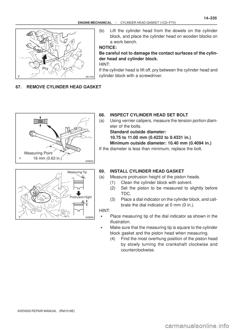
(b) Lift the cylinder head from the dowels on the cylinder
block, and place the cylinder head on wooden blocks on
a work bench.
NOTICE:
Be careful not to damage the contact surfaces of the cylin-
der head and cylinder block.
HINT:
If the cylinder head is lift off, pry between the cylinder head and
cylinder block with a screwdriver.
67. REMOVE CYLINDER HEAD GASKET
68. INSPECT CYLINDER HEAD SET BOLT
(a) Using vernier calipers, measure the tension portion diam-
eter of the bolts.
Standard outside diameter:
10.75 to 11.00 mm (0.4232 to 0.4331 in.)
Minimum outside diameter: 10.40 mm (0.4094 in.)
If the diameter is less than minimum, replace the bolt.
69. INSTALL CYLINDER HEAD GASKET
(a) Measure protrusion height of the piston heads.
(1) Clean the cylinder block with solvent.
(2) Set the piston to be measured to slightly before
TDC.
(3) Place a dial indicator on the cylinder block, and cali-
brate the dial indicator at 0 mm (0 in.).
HINT:
�Place measuring tip of the dial indicator as shown in the
illustration.
�Make sure that the measuring tip is square to the cylinder
block gasket and the piston head when measuring.
(4) Find the most overhung position of the piston head
by slowly turning the crankshaft clockwise and
counterclockwise.
Page 2316 of 5135
A09612
1st
2nd 5th
3rd
4th 6th 7th
A09589
Hexagon
Wrench
(1.27 mm)
(A)
A09623
A61179
Hexagon
Wrench
(1.27 mm)
A09605
Turn
Dot Mark
TDC Mark
14±310
± ENGINE MECHANICALTIMING BELT (1CD±FTV)
AVENSIS REPAIR MANUAL (RM1018E)
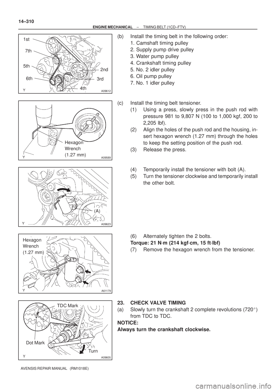
(b) Install the timing belt in the following order:
1. Camshaft timing pulley
2. Supply pump drive pulley
3. Water pump pulley
4. Crankshaft timing pulley
5. No. 2 idler pulley
6. Oil pump pulley
7. No. 1 idler pulley
(c) Install the timing belt tensioner.
(1) Using a press, slowly press in the push rod with
pressure 981 to 9,807 N (100 to 1,000 kgf, 200 to
2,205 lbf).
(2) Align the holes of the push rod and the housing, in-
sert hexagon wrench (1.27 mm) through the holes
to keep the setting position of the push rod.
(3) Release the press.
(4) Temporarily install the tensioner with bolt (A).
(5) Turn the tensioner clockwise and temporarily install
the other bolt.
(6) Alternately tighten the 2 bolts.
Torque: 21 N´m (214 kgf´cm, 15 ft´lbf)
(7) Remove the hexagon wrench from the tensioner.
23. CHECK VALVE TIMING
(a) Slowly turn the crankshaft 2 complete revolutions (720�)
from TDC to TDC.
NOTICE:
Always turn the crankshaft clockwise.
Page 2588 of 5135
320VT±01
G23220
G23175
F43108
Stop Lamp Switch Assy
Cushion
1.5 ± 2.5 mm (0.059 ± 0.098 in.)
±
BRAKE BRAKE PEDAL SUB±ASSY
32±9
AVENSIS REPAIR MANUAL (RM1018E)
REPLACEMENT
1.REMOVE COMBINATION METER ASSEMBLY (See page 71±21)
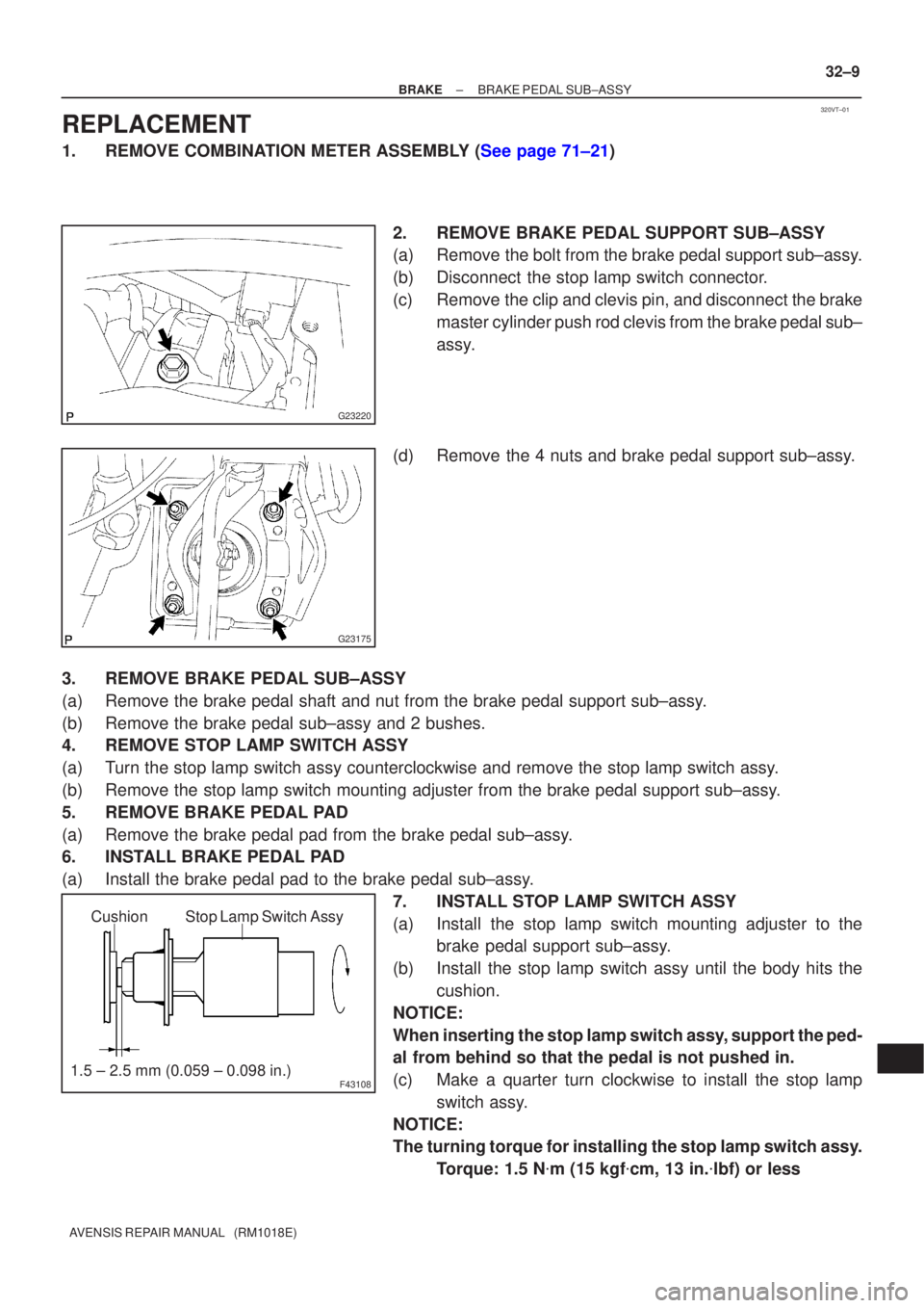
2. REMOVE BRAKE PEDAL SUPPORT SUB±ASSY
(a) Remove the bolt from the brake pedal support sub±assy.
(b) Disconnect the stop lamp switch connector.
(c) Remove the clip and clevis pin, and disconnect the brakemaster cylinder push rod clevis from the brake pedal sub±
assy.
(d) Remove the 4 nuts and brake pedal support sub±assy.
3. REMOVE BRAKE PEDAL SUB±ASSY
(a) Remove the brake pedal shaft and nut from the brake pedal support sub±\
assy.
(b) Remove the brake pedal sub±assy and 2 bushes.
4. REMOVE STOP LAMP SWITCH ASSY
(a) Turn the stop lamp switch assy counterclockwise and remove the stop lamp \
switch assy.
(b) Remove the stop lamp switch mounting adjuster from the brake pedal suppo\
rt sub±assy.
5. REMOVE BRAKE PEDAL PAD
(a) Remove the brake pedal pad from the brake pedal sub±assy.
6. INSTALL BRAKE PEDAL PAD
(a) Install the brake pedal pad to the brake pedal sub±assy. 7. INSTALL STOP LAMP SWITCH ASSY
(a) Install the stop lamp switch mounting adjuster to thebrake pedal support sub±assy.
(b) Install the stop lamp switch assy until the body hits the cushion.
NOTICE:
When inserting the stop lamp switch assy, support the ped-
al from behind so that the pedal is not pushed in.
(c) Make a quarter turn clockwise to install the stop lamp switch assy.
NOTICE:
The turning torque for installing the stop lamp switch assy. Torque: 1.5 N �m (15 kgf �cm, 13 in. �lbf) or less