Page 3581 of 5135
C94578
N´m (kgf´cm, ft´lbf) : Specified torque
Apply MP greaseSelecting Bellcrank Support
Selecting Bellcrank
Dust Cover No.2Selecting Bellcrank
No.2 Bush
Selecting Bellcrank No.2
Selecting Bellcrank
No.2 Bush
Selecting Bellcrank
No.2 Plate Washer
Selecting Bellcrank
Dust Cover No.1
Shift & Select
Lever Bush
12 (120, 9)
± MANUAL TRANSMISSION/TRANSAXLESHIFT & SELECT LEVER SHAFT ASSY (C250)
41±59
C250 M/T REPAIR MANUAL (RM1020E)
Page 3582 of 5135
4002J±01
D03796
SST
C67862
C67865
C67863
40±56
± AUTOMATIC TRANSMISSION / TRANSSECOND BRAKE PISTON ASSY (U34#E Series)
U340E A/T REPAIR MANUAL (RM824E)
SECOND BRAKE PISTON ASSY (U34#E Series)
OVERHAUL
1. REMOVE 2ND BRAKE PISTON RETURN SPRING
SUB±ASSY
[ 35608L / 3509 ]
(a) Place SST on the piston return spring and compress.
SST 09387±00060
(b) Using a screwdriver, remove the snap ring.
(c) Remove the 2nd brake return spring from the 2nd brake
cylinder.
2. INSPECT 2ND BRAKE PISTON RETURN SPRING
SUB±ASSY
[ 35608L / 3509 ]
(a) Using vernier calipers, measure the free length of the
spring together with the spring seat.
Standard free length: 14.65 mm (0.5768 in.)
3. REMOVE 2ND BRAKE PISTON
[ 35624E / 3509 ]
(a) Hold the 2nd brake piston and apply compressed air (392
kPa, 4.0 kgf�cm
2, 57 psi) to the 2nd brake cylinder to re-
move the 2nd brake piston.
Page 3583 of 5135

40±57
U340E A/T REPAIR MANUAL (RM824E)
4. REMOVE 2ND BRAKE CYLINDER O±RING
[ 35664D")
C67864
C67864
C67866
C67862
D03796
SST
± AUTOMATIC TRANSMISSION / TRANSSECOND BRAKE PISTON ASSY (U34#E Series)
40±57
U340E A/T REPAIR MANUAL (RM824E)
4. REMOVE 2ND BRAKE CYLINDER O±RING
[ 35664D / 3509 ]
(a) Using a screwdriver, remove the 2 O±rings from the 2nd
brake cylinder.
5. INSTALL 2ND BRAKE CYLINDER O±RING
[ 35664D / 3509 ]
(a) Install 2 new O±ring to the 2nd brake cylinder.
NOTICE:
Be careful not to damage the O±ring.
6. INSTALL 2ND BRAKE PISTON
[ 35624E / 3509 ]
(a) Coat 2 new O±rings with ATF and install them in the 2nd
brake cylinder.
(b) Be careful not to damage the O±rings and press in the
2nd brake piston into the 2nd brake cylinder with a your
hands.
7. INSTALL 2ND BRAKE PISTON RETURN SPRING
SUB±ASSY
[ 35608L / 3509 ]
(a) Install the piston return spring.
(b) Place SST on the piston return spring, and compress the
piston return spring with a press.
SST 09387±00060
(c) Using a screwdriver, install the snap ring.
NOTICE:
Be sure the end gap of the snap ring is not aligned with the
piston return spring claw.
Page 3594 of 5135
4002N±01
D25171
D25172
D25173
C81314
± AUTOMATIC TRANSMISSION / TRANSFRONNT DIFFERENTIAL ASSY (U34#E Series)
40±71
U340E A/T REPAIR MANUAL (RM824E)
FRONNT DIFFERENTIAL ASSY (U34#E Series)
OVERHAUL
1. REMOVE SPEEDOMETER DRIVE (ATM) GEAR
[ 33481X / 4301 ]
(a) Remove the speedometer drive gear from the differential
case.
2. REMOVE FRONT DIFFERENTIAL RING GEAR
[ 41221 / 4301 ]
(a) Put match±marks on the front differential ring gear and
differential case.
(b) Using SST and a hammer, unstake the lock plate.
SST 09930±00010
(c) Remove the 8 bolts and lock plate.
Page 3595 of 5135
C81315
C81316
C81317
C81318
C81319
40±72
± AUTOMATIC TRANSMISSION / TRANSFRONNT DIFFERENTIAL ASSY (U34#E Series)
U340E A/T REPAIR MANUAL (RM824E)
(d) Using a plastic hammer, remove the front differential ring
gear from the differential case.
3. REMOVE FRONT DIFFERENTIAL PINION SHAFT
STRAIGHT PIN
[ 41342A / 4301 ]
(a) Using a punch and a hammer, unstake the differential
case.
(b) Using a pin punch and a hammer, remove the straight pin.
4. REMOVE FRONT DIFFERENTIAL PINION SHAFT
NO.1
[ 41342F / 4301 ]
(a) Remove the pinion shaft from the front differential case.
5. REMOVE FRONT DIFFERENTIAL SIDE GEAR
[ 41331F / 4301 ]
(a) Remove the 2 pinions, 2 thrust washers, 2 side gears and
2 thrust washers No.1 from the front differential case.
Page 3596 of 5135

40±73
U340E A/T REPAIR MANUAL (RM824E)
6. REMOVE DIFFERENTIAL DRIVE PINION PLUG
[ 41")
C68188
D25174
SST
D25175
SST
D25176
SST
± AUTOMATIC TRANSMISSION / TRANSFRONNT DIFFERENTIAL ASSY (U34#E Series)
40±73
U340E A/T REPAIR MANUAL (RM824E)
6. REMOVE DIFFERENTIAL DRIVE PINION PLUG
[ 41211E / 4301 ]
(a) Using a brass bar and a hammer, remove the differential
drive pinion plug.
7. REMOVE COUNTER DRIVEN GEAR
[ 35783R / 4301 ]
(a) Using SST and a press, remove the counter driven gear
from the differential drive pinion.
SST 09950±60010 (09951±00350), 09950±70010
(09951±07150)
8. INSTALL COUNTER DRIVEN GEAR
[ 35783R / 4301 ]
(a) Using SST and a press, install the counter driven gear to
the differential drive pinion.
SST 09950±60010 (09951±00350), 09950±70010
(09951±07150)
NOTICE:
When replacing the counter driven gear, replace the count-
er drive gear in the transaxle case, too.
HINT:
The differential drive pinion shall be press±fit until it comes to
contact with the counter driven gear.
9. INSTALL DIFFERENTIAL DRIVE PINION PLUG
[ 41211E / 4301 ]
(a) Using SST and a plastic hammer, install a new differential
drive pinion plug to the differential drive pinion
SST 09221±25026 (09221±00071)
Standard clearance:
2.5 ± 2.6 mm (0.0984 ± 0.1023 in.)
Page 3597 of 5135
![TOYOTA AVENSIS 2005 Service Repair Manual C81320
C81321
C81322
40±74
± AUTOMATIC TRANSMISSION / TRANSFRONNT DIFFERENTIAL ASSY (U34#E Series)
U340E A/T REPAIR MANUAL (RM824E)
10. INSTALL FRONT DIFFERENTIAL SIDE GEAR
[ 41331F / 4301 ]
(a) A](/manual-img/14/57441/w960_57441-3596.png "TOYOTA AVENSIS 2005 Service Repair Manual C81320
C81321
C81322
40±74
± AUTOMATIC TRANSMISSION / TRANSFRONNT DIFFERENTIAL ASSY (U34#E Series)
U340E A/T REPAIR MANUAL (RM824E)
10. INSTALL FRONT DIFFERENTIAL SIDE GEAR
[ 41331F / 4301 ]
(a) A")
C81320
C81321
C81322
40±74
± AUTOMATIC TRANSMISSION / TRANSFRONNT DIFFERENTIAL ASSY (U34#E Series)
U340E A/T REPAIR MANUAL (RM824E)
10. INSTALL FRONT DIFFERENTIAL SIDE GEAR
[ 41331F / 4301 ]
(a) After applying ATF to the 2 front differential side gears, 2
side gear thrust washers No. 1, 2 front differential pinions
and 2 pinion thrust washers, install them to the front differ-
ential case.
HINT:
At the time of installation, set the alignment of the front differen-
tial pinions perpendicular to that of the side gear and rotate
them so that their holes will be aligned with the holes in the dif-
ferential case.
11. INSTALL FRONT DIFFERENTIAL PINION SHAFT NO.1
[ 41342F / 4301 ]
(a) Install the pinion shaft so as to align the lock pin holes on
the pinion shaft and differential case.
12. INSPECT BACKLASH
(a) Measure the side gear backlash while holding 1 pinion
gear toward the case.
Standard backlash:
0.05 ± 0.20 mm (0.0020 ± 0.0079 in.)
If the backlash is out of specification, install the correct thrust
washer to the side gear.
(b) Referring to the table below, select thrust washers which
will ensure that the backlash is within for both sides.
Thrust washer thickness: mm (in.)
ThicknessThickness
0.95 (0.0374)1.10 (0.0433)
1.00 (0.0394)1.15 (0.0453)
1.05 (0.0413)1.20 (0.0472)
If the backlash is not within the specification, install a thrust
washer of a different thickness.
Page 3598 of 5135
C81323
C81324
D25177
C81325
���
C81326
± AUTOMATIC TRANSMISSION / TRANSFRONNT DIFFERENTIAL ASSY (U34#E Series)
40±75
U340E A/T REPAIR MANUAL (RM824E)
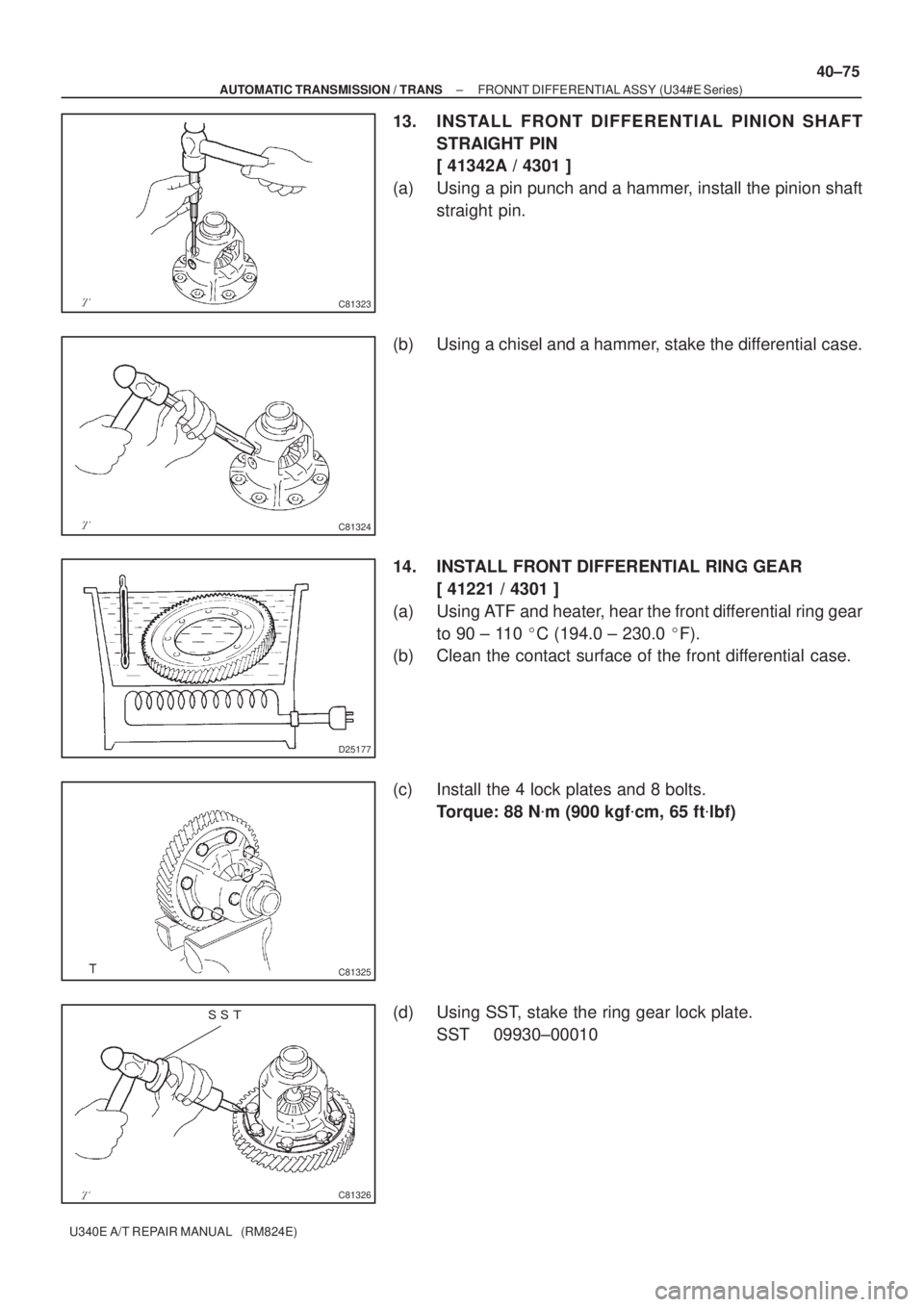
13. INSTALL FRONT DIFFERENTIAL PINION SHAFT
STRAIGHT PIN
[ 41342A / 4301 ]
(a) Using a pin punch and a hammer, install the pinion shaft
straight pin.
(b) Using a chisel and a hammer, stake the differential case.
14. INSTALL FRONT DIFFERENTIAL RING GEAR
[ 41221 / 4301 ]
(a) Using ATF and heater, hear the front differential ring gear
to 90 ± 110 �C (194.0 ± 230.0 �F).
(b) Clean the contact surface of the front differential case.
(c) Install the 4 lock plates and 8 bolts.
Torque: 88 N�m (900 kgf�cm, 65 ft�lbf)
(d) Using SST, stake the ring gear lock plate.
SST 09930±00010
 : Specified torque
Apply MP greaseSelecting Bellcrank Support
Selecting Bellcrank
Dust Cover No.2Selecting Bellcrank
No.2 Bush
Selecting Bellcrank No.2
Selecting Bellc")

U340E A/T REPAIR MANUAL (RM824E)
SECOND BRAKE PISTON ASSY (U34#E Series)
OVE")

40±71
U340E A/T REPAIR MANUAL (RM824E)
FRONNT DIFFERENTIAL ASSY (U34#E Series)
OVERHAU")

U340E A/T REPAIR MANUAL (RM824E)
(d) Using a plastic hammer, remove the front diffe")