Page 3599 of 5135
D25171
40±76
± AUTOMATIC TRANSMISSION / TRANSFRONNT DIFFERENTIAL ASSY (U34#E Series)
U340E A/T REPAIR MANUAL (RM824E)
15. INSTALL SPEEDOMETER DRIVE (ATM) GEAR
[ 33481X / 4301 ]
(a) Install the speedometer drive gear to the differential case.
Page 3600 of 5135
4002M±01
C67905
C67904
C82123
C67908
± AUTOMATIC TRANSMISSION / TRANSTRANSMISSION VALVE BODY ASSY (U34#E Series)
40±67
U340E A/T REPAIR MANUAL (RM824E)
TRANSMISSION VALVE BODY ASSY (U34#E Series)
OVERHAUL
1. REMOVE LINE PRESSURE CONTROL SOLENOID
ASSY
[ 35290A / 3512 ]
(a) Remove the bolt, and pull out the line pressure control so-
lenoid assy.
2. REMOVE TRANSMISSION 3WAY SOLENOID ASSY
NO.3
[ 35250A / 3512 ]
(a) Remove the bolt, and pull out the transmission 3 way so-
lenoid assy No. 3.
3. REMOVE LOCK UP CONTROL SOLENOID ASSY
[ 35280 / 3512 ]
(a) Remove the bolt, and pull out the lock up control solenoid
assy.
4. REMOVE TRANSMISSION 3WAY SOLENOID ASSY
NO.2
[ 35230 / 3512 ]
(a) Remove the bolt, and pull out the transmission 3 way so-
lenoid assy No. 2.
Page 3601 of 5135
C67907
C67910
C67910
C67907
C67908
40±68
± AUTOMATIC TRANSMISSION / TRANSTRANSMISSION VALVE BODY ASSY (U34#E Series)
U340E A/T REPAIR MANUAL (RM824E)
5. REMOVE AUTOMATIC TRANSMISSION 3WAY
SOLENOID ASSY
[ 35240 / 3512 ]
(a) Remove the bolt, and pull out the automatic transmission
3 way solenoid assy.
6. REMOVE MANUAL VALVE
[ 35418 / 3512 ]
(a) Remove the manual valve from the valve body assy.
7. INSTALL MANUAL VALVE
[ 35418 / 3512 ]
(a) Coat the manual valve with ATF and install it to the valve
body assy.
8. INSTALL AUTOMATIC TRANSMISSION 3WAY
SOLENOID ASSY
[ 35240 / 3512 ]
(a) Install the automatic transmission 3 way solenoid assy
with the bolt.
Torque: 11 N�m (110 kgf�cm, 8 ft�lbf)
9. INSTALL TRANSMISSION 3WAY SOLENOID ASSY
NO.2
[ 35230 / 3512 ]
(a) Install the transmission 3 way solenoid assy No. 2 with the
bolt.
Torque: 11 N�m (110 kgf�cm, 8 ft�lbf)
Page 3602 of 5135

40±69
U340E A/T REPAIR MANUAL (RM824E)
10. INSTALL LOCK UP CONTROL SO")
C82123
C67904
C67905
D25170
A
C
BA
A DB
�
�
C62687
± AUTOMATIC TRANSMISSION / TRANSTRANSMISSION VALVE BODY ASSY (U34#E Series)
40±69
U340E A/T REPAIR MANUAL (RM824E)
10. INSTALL LOCK UP CONTROL SOLENOID ASSY
[ 35280 / 3512 ]
(a) Install the lock up control solenoid assy with the bolt.
Torque: 11 N�m (110 kgf�cm, 8 ft�lbf)
11. INSTALL TRANSMISSION 3WAY SOLENOID ASSY
NO.3
[ 35250A / 3512 ]
(a) Install the transmission 3 way solenoid assy No. 3 with the
bolt.
Torque: 11 N�m (110 kgf�cm, 8 ft�lbf)
12. INSTALL LINE PRESSURE CONTROL SOLENOID
ASSY
[ 35290A / 3512 ]
(a) Install the line pressure control solenoid assy with the
bolt.
Torque: 11 N�m (110 kgf�cm, 8 ft�lbf)
13. TIGHTEN BOLT
(a) Install the valve body assembly and 13 bolts.
Torque: 11 N�m (110 kgf�cm, 8 ft�lbf)
Bolt length:
Bolt A: 32 mm (1.26 in.)
Bolt B: 22 mm (0.87 in.)
Bolt C: 55 mm (2.17 in.)
Bolt D: 45 mm (1.77 in.)
(b) Install the detente spring, detente spring cover and 2
bolts.
Torque: 11 N�m (110 kgf�cm, 8 ft�lbf)
Bolt length:
Bolt A: 14 mm (0.55 in.)
Bolt B: 45 mm (1.77 in.)
(c) Check that the manual valve lever is touching the center
of the detente spring tip roller.
Page 3603 of 5135
�
�
� ��
�
C67914
C67911
40±70
± AUTOMATIC TRANSMISSION / TRANSTRANSMISSION VALVE BODY ASSY (U34#E Series)
U340E A/T REPAIR MANUAL (RM824E)
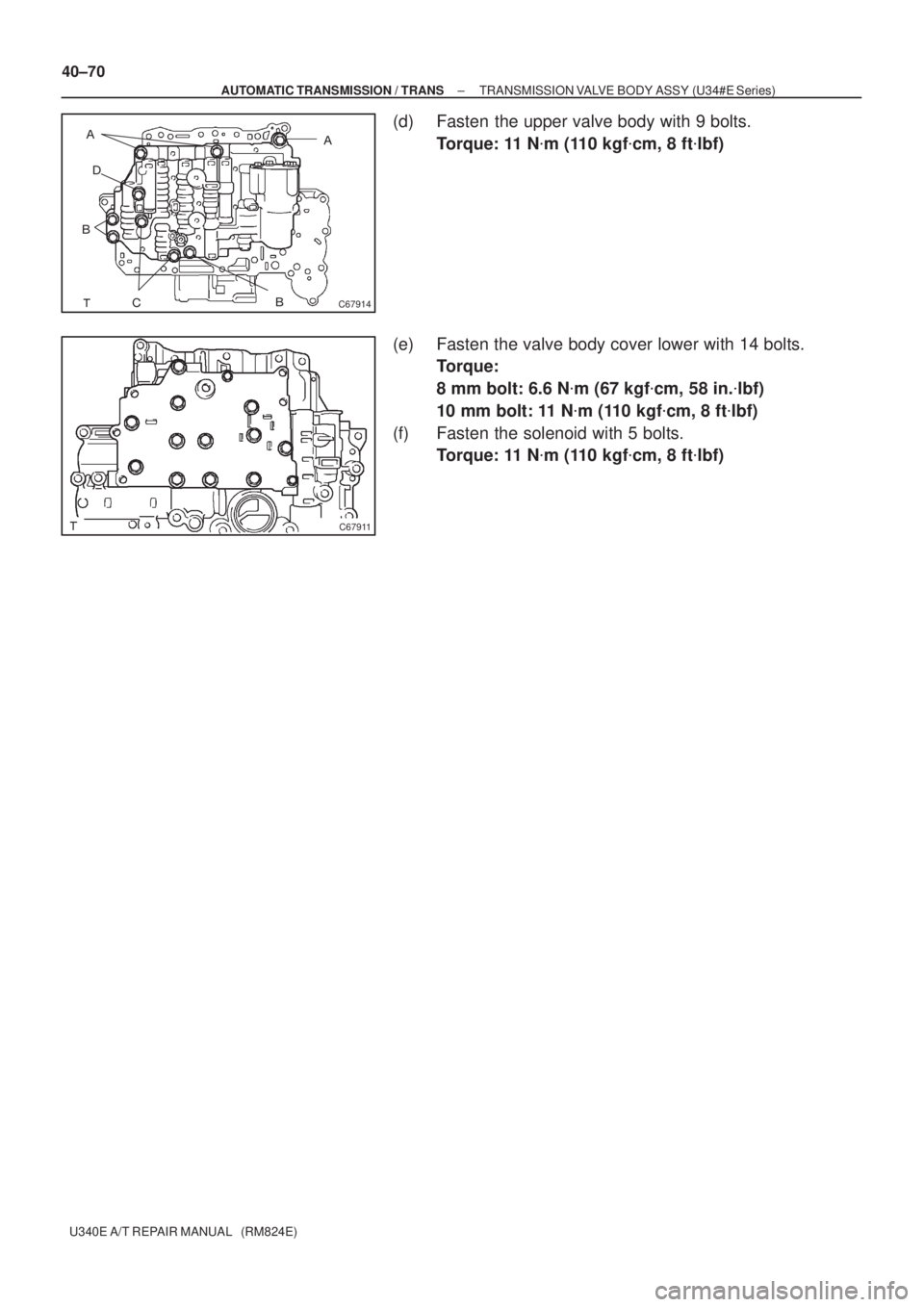
(d) Fasten the upper valve body with 9 bolts.
Torque: 11 N�m (110 kgf�cm, 8 ft�lbf)
(e) Fasten the valve body cover lower with 14 bolts.
Torque:
8 mm bolt: 6.6 N�m (67 kgf�cm, 58 in.�lbf)
10 mm bolt: 11 N�m (110 kgf�cm, 8 ft�lbf)
(f) Fasten the solenoid with 5 bolts.
Torque: 11 N�m (110 kgf�cm, 8 ft�lbf)
Page 3604 of 5135

U340E A/T REPAIR MANUAL (RM824E)
TRANSAXLE REAR COVER ASSY (U34#E Series)
OVERH")
4002L±01
C67881
D08358
C59838
C67883
40±64
± AUTOMATIC TRANSMISSION / TRANSTRANSAXLE REAR COVER ASSY (U34#E Series)
U340E A/T REPAIR MANUAL (RM824E)
TRANSAXLE REAR COVER ASSY (U34#E Series)
OVERHAUL
1. REMOVE TRANSAXLE REAR COVER PLUG
[ 35102B / 3503 ]
(a) Remove the 4 transaxle rear cover plug from the trans-
axle rear cover.
(b) Using a screwdriver, remove the O±ring from the trans-
axle rear cover plug.
2. REMOVE OVERDRIVE BRAKE RETURN SPRING
SUB±ASSY
[ 34603B / 3509 ]
(a) Using SST, a press and a screwdriver, remove the snap
ring.
SST 09387±00070
NOTICE:
Stop the press when the O/D brake piston is lowered 1 ± 2
mm (0.039 ± 0.078 in.) from the snap ring groove, prevent-
ing the O/D brake piston from being deformed.
(b) Remove the O/D brake return spring.
3. INSPECT OVERDRIVE BRAKE RETURN SPRING
SUB±ASSY
[ 34603B / 3509 ]
(a) Using a vernier calipers, measure the free length of the
spring together with the spring seat.
Standard free length: 17.88mm (0.7039 in.)
4. REMOVE 2ND COAST & OVERDRIVE BRAKE PISTON
[ 34622B / 3509 ]
(a) Apply compressed air (392 kPa, 4.0 kgf�cm
2, 57 psi) to the
transaxle rear cover to remove the O/D brake piston.
NOTICE:
�Blowing off the air may cause the piston's jump±out.
When removing the piston, holding it with your hand
using a waste cloth.
�Take care not to splash ATF when air±blowing.
Page 3605 of 5135

40±65
U340E A/T REPAIR MANUAL (RM824E)
5. REMOVE 2ND COAST & OVERDRIV")
C67884
C67885
HoldTurn
SST
C82194
���
C67888
D25116
A
± AUTOMATIC TRANSMISSION / TRANSTRANSAXLE REAR COVER ASSY (U34#E Series)
40±65
U340E A/T REPAIR MANUAL (RM824E)
5. REMOVE 2ND COAST & OVERDRIVE O±RING
[ 34622C / 3509 ]
(a) Using a screwdriver, remove the 2 O±ring from the 2nd
coast & O/D brake piston.
6. REMOVE CLUTCH DRUM OIL SEAL RING
[ 35617G / 3507 ]
(a) Remove the 3 oil seals.
7. REMOVE TRANSAXLE REAR COVER NEEDLE
ROLLER BEARING
[ 35102D / 3503 ]
(a) Using SST, remove the bearing.
SST 09387±00040 (09387±01020)
8. INSTALL TRANSAXLE REAR COVER NEEDLE
ROLLER BEARING
[ 35102D / 3503 ]
(a) Using SST and a press, install the new bearing to the
transaxle rear cover.
SST 09950±60010 (09951±00190, 09952±06010),
09950±70010 (09951±07100)
Standard clearance: 25.2 mm (0.992 in.)
9. INSTALL CLUTCH DRUM OIL SEAL RING
[ 35617G / 3507 ]
(a) Compress the oil seal ring from both sides to reduce di-
mension A.
Dimension A: 5.0 mm (0.197 in.)
(b) Coat the oil seal ring with ATF and install it to the transaxle
rear cover.
Page 3606 of 5135

U340E A/T REPAIR MANUAL (RM824E)
10. INSTALL 2ND COAST & OVERDRIVE O±RING
[ 34622C / 350")
C67884
C67889
D08358
C67881
40±66
± AUTOMATIC TRANSMISSION / TRANSTRANSAXLE REAR COVER ASSY (U34#E Series)
U340E A/T REPAIR MANUAL (RM824E)
10. INSTALL 2ND COAST & OVERDRIVE O±RING
[ 34622C / 3509 ]
(a) Coat the 2 new O±rings with ATF, install them to the trans-
axle rear cover.
NOTICE:
Be careful not to damage the oil seal lip.
11. INSTALL 2ND COAST & OVERDRIVE BRAKE PISTON
[ 34622B / 3509 ]
(a) Coat the piston with ATF, install it to the transaxle rear cov-
er.
NOTICE:
Be careful not to damage the oil seal lip.
12. INSTALL OVERDRIVE BRAKE RETURN SPRING
SUB±ASSY
[ 34603B / 3509 ]
(a) Using SST and a press, install the O/D brake return spring
and snap ring to the transaxle rear cover.
SST 09387±00070
NOTICE:
Stop the press when the O/D brake piston is lowered 1 ± 2
mm (0.039 ± 0.078 in.) from the snap ring groove, prevent-
ing the O/D brake piston from being deformed.
13. INSTALL TRANSAXLE REAR COVER PLUG
[ 35102B / 3503 ]
(a) Install 4 new O±rings and the 4 screw plugs to the trans-
axle rear cover.
Torque: 7.4 N�m (75 kgf�cm, 65 in.�lbf)
NOTICE:
Be careful not to damage the oil seal lip.
![TOYOTA AVENSIS 2005 Service Repair Manual D25171
40±76
± AUTOMATIC TRANSMISSION / TRANSFRONNT DIFFERENTIAL ASSY (U34#E Series)
U340E A/T REPAIR MANUAL (RM824E)
15. INSTALL SPEEDOMETER DRIVE (ATM) GEAR
[ 33481X / 4301 ]
(a) Install the spe](/manual-img/14/57441/w960_57441-3598.png "TOYOTA AVENSIS 2005 Service Repair Manual D25171
40±76
± AUTOMATIC TRANSMISSION / TRANSFRONNT DIFFERENTIAL ASSY (U34#E Series)
U340E A/T REPAIR MANUAL (RM824E)
15. INSTALL SPEEDOMETER DRIVE (ATM) GEAR
[ 33481X / 4301 ]
(a) Install the spe")

40±67
U340E A/T REPAIR MANUAL (RM824E)
TRANSMISSION VALVE BODY ASSY (U34#E Series)")

U340E A/T REPAIR MANUAL (RM824E)
5. REMOVE AUTOMATIC TRANSMISSION 3WAY
SOLENOID")