Page 498 of 5135

05±326
± DIAGNOSTICSSFI SYSTEM (1AZ±FSE)
AVENSIS REPAIR MANUAL (RM1018E)
2 PERFORM ACTIVE TEST BY HAND±HELD TESTER(OPERATE OCV)
(a) Connect the hand±held tester to the DLC3.
(b) Start the engine and warm it up.
(c) Turn the ignition switch ON and push the hand±held tester main switch ON.
(d) Select the item ºDIAGNOSIS / OBD/MOBD / ACTIVE TEST / VVT CTRL B1º.
(e) Check the engine speed when operating the OCV by the hand±held tester.
Standard:
Tester operationSpecified condition
OCV is OFFNormal engine speed
OCV is ONRough idle or engine stall
NG Go to step 4
OK
3 CHECK IF DTC OUTPUTS REOCCUR
(a) Clear the DTC.
(1) Operating the hand±held tester to erase the codes, or disconnecting the battery terminal or the
EFI and ETCS fuses for 60 seconds or more.
(b) Start the engine and warm it up.
(c) Drive the vehicle around for 10 minutes or more.
(d) Read output DTC using the hand±held tester.
Standard: No DTC output.
HINT:
*: DTCs P0011 or P0012 is output when a foreign object in engine oil is caught in some part of the system.
These codes will stay registered even if the system returns to normal after a short time. These foreign objects
are then captured by the oil filter, thus eliminating the source of the problem.
OK VVT SYSTEM OK *
NG
Page 499 of 5135
A67528
OCV Signal Waveform1 msec./Division 5 V/
Division
GND
(A)(A) (A)
E11
OC1 +OC1±
±
DIAGNOSTICS SFI SYSTEM(1AZ±FSE)
05±327
AVENSIS REPAIR MANUAL (RM1018E)
4INSPECT ECM(OCV SIGNAL)
(a)Inspection using the oscilloscope.
(b)During idling, check the waveform between the terminals
of the E11 ECM connector.
Standard:
Symbols (Terminal No.)Specified condition
OC1+ (E11±16) ± OC1± (E11±15)Correct waveform is as shown
HINT:
The waveform frequency (A) is lengthened as the engine speed
becomes higher.
NGCHECK AND REPLACE ECM (See page 01±32)
OK
5 INSPECT OIL CONTROL VALVE FILTER
NG REPLACE OIL CONTROL VALVE FILTER
OK
6 INSPECT CAMSHAFT TIMING OIL CONTROL VALVE ASSY(OCV) (See page 10±39)
OK Go to step 8
NG
7 REPLACE CAMSHAFT TIMING OIL CONTROL VALVE ASSY(OCV)
GO
8INSPECT CAMSHAFT TIMING GEAR ASSY (See page 14±240)
OK Go to step 10
NG
Page 500 of 5135
05±328
±
DIAGNOSTICS SFI SYSTEM(1AZ±FSE)
AVENSIS REPAIR MANUAL (RM1018E)
9REPLACE CAMSHAFT TIMING GEAR ASSY (See page 14±240)
GO
10CHECK BLOCKAGE(OCV, OIL CHECK VALVE AND OIL HOLE)
NGREPAIR OR REPLACE
OK
11CHECK IF DTC OUTPUTS REOCCUR
(a)Clear the DTC. (1)Operating the hand±held tester to erase the codes, or disconnecting the batter\
y terminal or the
EFI and ETCS fuses for 60 seconds or more.
(b)Start the engine and warm it up.
(c)Drive the vehicle around for 10 minutes or more.
(d)Read output DTC using the hand±held tester.
Standard: No DTC output.
HINT:
*: DTCs P0011 or P0012 is output when a foreign object in engine oil is caught in so\
me part of the system.
These codes will stay registered even if the system returns to normal after a\
short time. These foreign objects
are then captured by the oil filter, thus eliminating the source of the problem.
OKVVT SYSTEM OK
NG
CHECK AND REPLACE ECM (See page 01±32)
Page 501 of 5135

A71007
Air Flow Meter Crankshaft Position Sensor
Actual Valve TimingCorrection Target Valve Timing
Feedback
Duty Control ECM
Camshaft Timing
Oil Control
Valve (OCV)
Vehicle Speed Signal Engine Coolant Temp. SensorThrottle Position Sensor
Camshaft Position Sensor
05±322
± DIAGNOSTICSSFI SYSTEM (1AZ±FSE)
AVENSIS REPAIR MANUAL (RM1018E)
DTC P0010 CAMSHAFT POSITION ºAº ACTUATOR
CIRCUIT (BANK 1)
HINT:
This is the procedure of oil control valve (OCV).
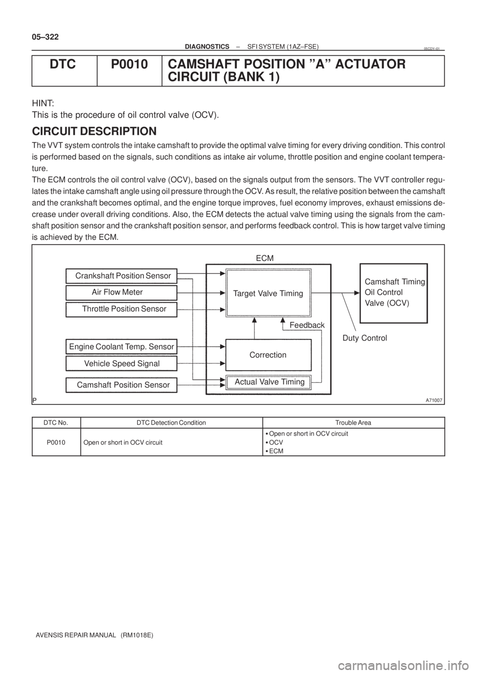
CIRCUIT DESCRIPTION
The VVT system controls the intake camshaft to provide the optimal valve timing for every driving condition. This control
is performed based on the signals, such conditions as intake air volume, throttle position and engine coolant tempera-
ture.
The ECM controls the oil control valve (OCV), based on the signals output from the sensors. The VVT controller regu-
lates the intake camshaft angle using oil pressure through the OCV. As result, the relative position between the camshaft
and the crankshaft becomes optimal, and the engine torque improves, fuel economy improves, exhaust emissions de-
crease under overall driving conditions. Also, the ECM detects the actual valve timing using the signals from the cam-
shaft position sensor and the crankshaft position sensor, and performs feedback control. This is how target valve timing
is achieved by the ECM.
DTC No.DTC Detection ConditionTrouble Area
P0010Open or short in OCV circuit
�Open or short in OCV circuit
�OCV
�ECM
05CDY±01
Page 502 of 5135

A59779
C2
Camshaft Timing Oil
Control Valve1
2 ECM
W±G OC1+
15
Y±B OC1±
E11
16
E11
±
DIAGNOSTICS SFI SYSTEM(1AZ±FSE)
05±323
AVENSIS REPAIR MANUAL (RM1018E)
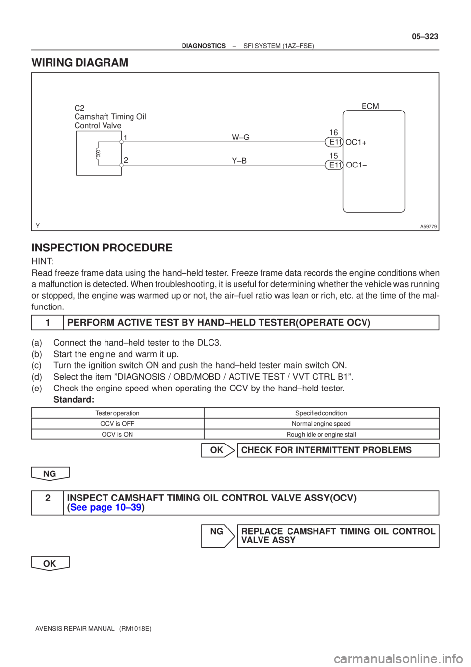
WIRING DIAGRAM
INSPECTION PROCEDURE
HINT:
Read freeze frame data using the hand±held tester. Freeze frame data records the engine conditions when
a malfunction is detected. When troubleshooting, it is useful for determi\
ning whether the vehicle was running
or stopped, the engine was warmed up or not, the air±fuel ratio was lea\
n or rich, etc. at the time of the mal-
function.
1PERFORM ACTIVE TEST BY HAND±HELD TESTER(OPERATE OCV)
(a)Connect the hand±held tester to the DLC3.
(b)Start the engine and warm it up.
(c)Turn the ignition switch ON and push the hand±held tester main switch \
ON.
(d)Select the item ºDIAGNOSIS / OBD/MOBD / ACTIVE TEST / VVT CTRL B1º\
.
(e)Check the engine speed when operating the OCV by the hand±held tester.
Standard:
Tester operationSpecified condition
OCV is OFFNormal engine speed
OCV is ONRough idle or engine stall
OKCHECK FOR INTERMITTENT PROBLEMS
NG
2INSPECT CAMSHAFT TIMING OIL CONTROL VALVE ASSY(OCV) (See page 10±39)
NG REPLACE CAMSHAFT TIMING OIL CONTROL VALVE ASSY
OK
Page 503 of 5135

A67528
OCV Signal Waveform1 msec./Division 5 V/
Division
GND
(A)(A) (A)
E11
OC1 +OC1±
A54386
Wire Harness Side
C2
OCV Connector
A81698ECM Connector E11
OC1+
OC1±
05±324
±
DIAGNOSTICS SFI SYSTEM(1AZ±FSE)
AVENSIS REPAIR MANUAL (RM1018E)
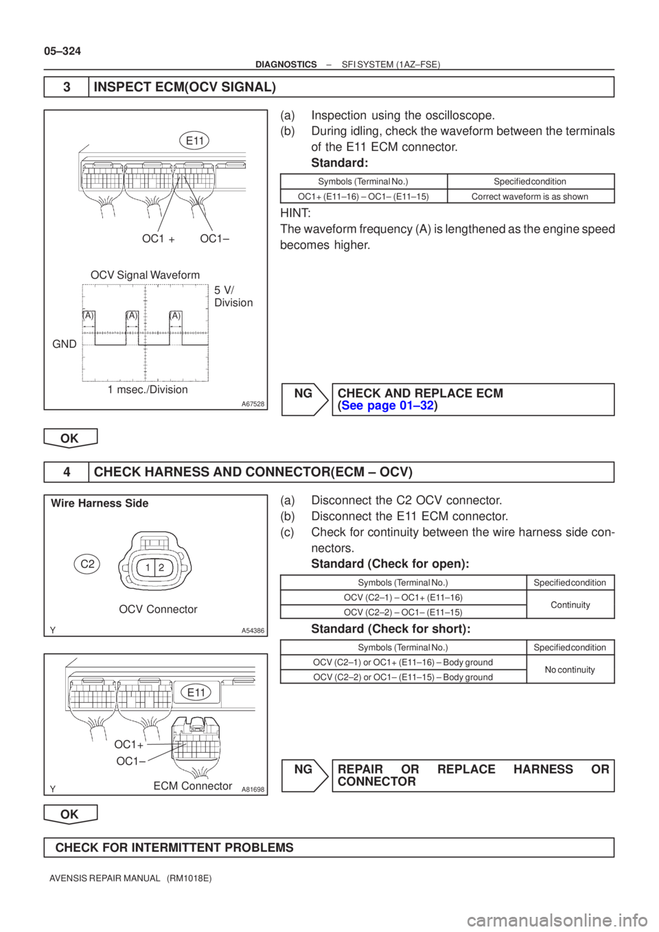
3INSPECT ECM(OCV SIGNAL)
(a)Inspection using the oscilloscope.
(b)During idling, check the waveform between the terminals of the E11 ECM connector.
Standard:
Symbols (Terminal No.)Specified condition
OC1+ (E11±16) ± OC1± (E11±15)Correct waveform is as shown
HINT:
The waveform frequency (A) is lengthened as the engine speed
becomes higher.
NGCHECK AND REPLACE ECM (See page 01±32)
OK
4 CHECK HARNESS AND CONNECTOR(ECM ± OCV)
(a) Disconnect the C2 OCV connector.
(b) Disconnect the E11 ECM connector.
(c) Check for continuity between the wire harness side con- nectors.
Standard (Check for open):
Symbols (Terminal No.)Specified condition
OCV (C2±1) ± OC1+ (E11±16)ContinuityOCV (C2±2) ± OC1± (E11±15)Continuity
Standard (Check for short):
Symbols (Terminal No.)Specified condition
OCV (C2±1) or OC1+ (E11±16) ± Body groundNo continuityOCV (C2±2) or OC1± (E11±15) ± Body groundNo continuity
NG REPAIR OR REPLACE HARNESS OR CONNECTOR
OK
CHECK FOR INTERMITTENT PROBLEMS
Page 504 of 5135

05CDX±01
05±320
±
DIAGNOSTICS SFI SYSTEM(1AZ±FSE)
AVENSIS REPAIR MANUAL (RM1018E)
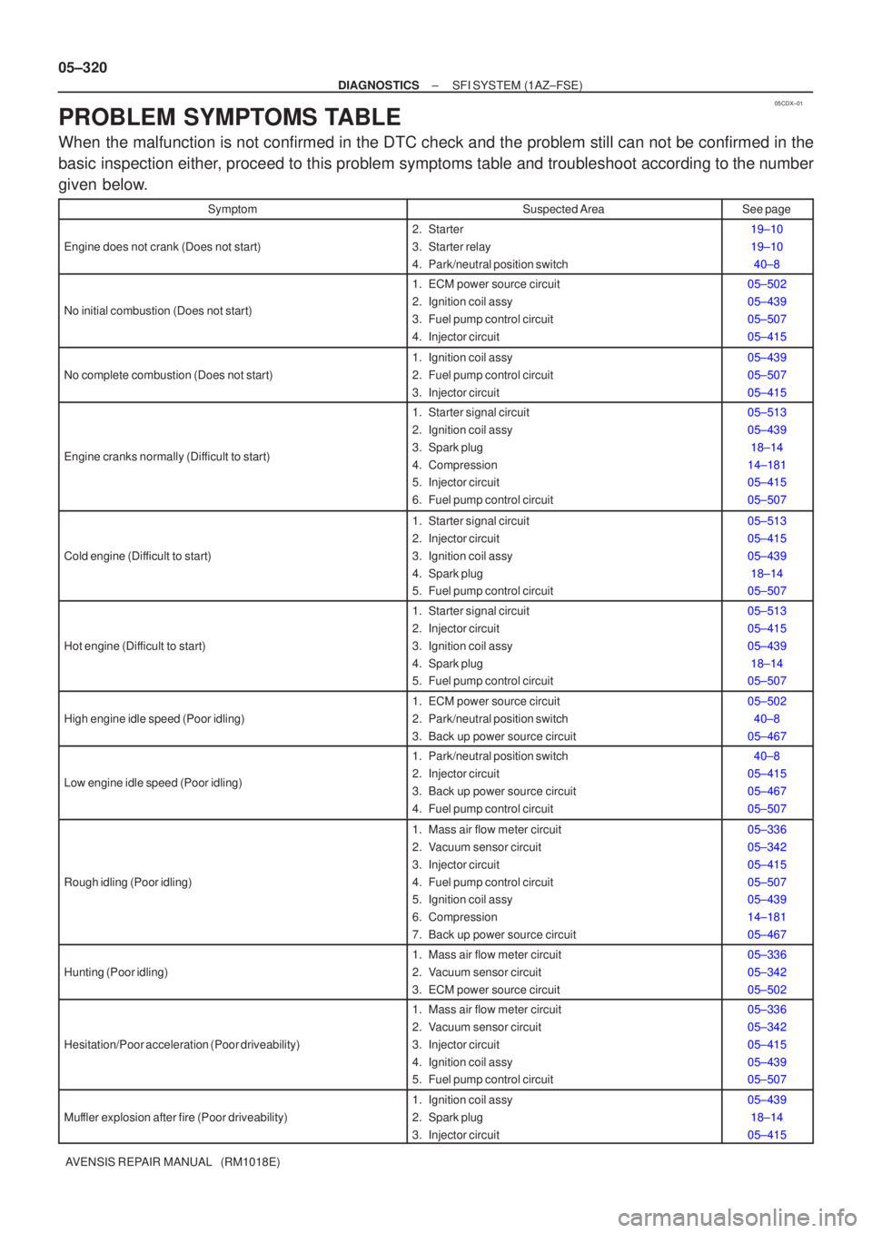
PROBLEM SYMPTOMS TABLE
When the malfunction is not confirmed in the DTC check and the problem still\
can not be confirmed in the
basic inspection either, proceed to this problem symptoms table and troubleshoot according to the number
given below.
SymptomSuspected AreaSee page
Engine does not crank (Does not start)
2. Starter
3. Starter relay
4. Park/neutral position switch19±10
19±10 40±8
No initial combustion (Does not start)
1. ECM power source circuit
2. Ignition coil assy
3. Fuel pump control circuit
4. Injector circuit05±502
05±439
05±507
05±415
No complete combustion (Does not start)
1. Ignition coil assy
2. Fuel pump control circuit
3. Injector circuit05±439
05±507
05±415
Engine cranks normally (Difficult to start)
1. Starter signal circuit
2. Ignition coil assy
3. Spark plug
4. Compression
5. Injector circuit
6. Fuel pump control circuit05±513
05±43918±14
14±181
05±415
05±507
Cold engine (Difficult to start)
1. Starter signal circuit
2. Injector circuit
3. Ignition coil assy
4. Spark plug
5. Fuel pump control circuit05±513
05±415
05±439 18±14
05±507
Hot engine (Difficult to start)
1. Starter signal circuit
2. Injector circuit
3. Ignition coil assy
4. Spark plug
5. Fuel pump control circuit05±513
05±415
05±439
18±14
05±507
High engine idle speed (Poor idling)
1. ECM power source circuit
2. Park/neutral position switch
3. Back up power source circuit05±502
40±8
05±467
Low engine idle speed (Poor idling)
1. Park/neutral position switch
2. Injector circuit
3. Back up power source circuit
4. Fuel pump control circuit40±8
05±415
05±467
05±507
Rough idling (Poor idling)
1. Mass air flow meter circuit
2. Vacuum sensor circuit
3. Injector circuit
4. Fuel pump control circuit
5. Ignition coil assy
6. Compression
7. Back up power source circuit05±336
05±342
05±415
05±507
05±439
14±181
05±467
Hunting (Poor idling)
1. Mass air flow meter circuit
2. Vacuum sensor circuit
3. ECM power source circuit05±336
05±342
05±502
Hesitation/Poor acceleration (Poor driveability)
1. Mass air flow meter circuit
2. Vacuum sensor circuit
3. Injector circuit
4. Ignition coil assy
5. Fuel pump control circuit05±336
05±342
05±415
05±439
05±507
Muffler explosion after fire (Poor driveability)
1. Ignition coil assy
2. Spark plug
3. Injector circuit05±439 18±14
05±415
Page 505 of 5135
±
DIAGNOSTICS SFI SYSTEM(1AZ±FSE)
05±321
AVENSIS REPAIR MANUAL (RM1018E) Symptom
See page
Suspected Area
Surging (Poor driveability)1. Spark plug
2. Injector circuit18±14
05±415
Engine stall (Soon after starting)1. Mass air flow meter circuit
2. Vacuum sensor circuit05±336
05±342
Engine stall (After accelerator pedal depressed)1. Mass air flow meter circuit
2. Vacuum sensor circuit05±336
05±342
Engine stall (After accelerator pedal released)
1. Mass air flow meter circuit
2. Vacuum sensor circuit
3. ECM05±336
05±342 01±32
Engine stall (During A/C operation)1. A/C signal circuit (Compressor circuit)
2. ECM05±1100 01±32
Engine stall (When shifting N to D)1. Park/neutral position switch40±8