Page 530 of 5135

05±395
AVENSIS REPAIR MANUAL (RM1018E)
�If the total of the short±term fuel trim value and long±term fuel tri\
m value is within � 25 % (Engine cool-
ant temp")
±
DIAGNOSTICS SFI SYSTEM(1AZ±FSE)
05±395
AVENSIS REPAIR MANUAL (RM1018E)
�If the total of the short±term fuel trim value and long±term fuel tri\
m value is within � 25 % (Engine cool-
ant temperature is greater than 75 �C), the system is functioning normally.
�Bank 1 refers to the No. 1 and No. 4 cylinders.
�Bank 2 refers to the No. 2 and No. 3 cylinders.
WIRING DIAGRAM
Refer to DTC P0130 on page 05±363.
INSPECTION PROCEDURE
HINT:
Hand±held tester only:
Narrowing down the trouble area is possible by performing the ºA/F CONTROLº ACTIVE TEST (heated oxy-
gen sensor or other trouble areas can be distinguished).
(a) Perform ACTIVE TEST using the hand±held tester (A/F CONTROL).
HINT:
ºA/F CONTROLº is an ACTIVE TEST which changes the injection volume\
±12.5 % or +25 %.
(1) Connect the hand±held tester to the DLC3 on the vehicle.
(2) Turn the ignition switch ON.
(3) Warm up the engine by running the engine at 2,500 rpm for approximately 9\
0 sec.
(4) Select the item ºDIAGNOSIS / OBD/MOBD / ACTIVE TEST / A/F CONTROLº\
.
(5) Perform ºA/F CONTROLº with the engine in an idle condition (press\
the right or left button).
Result:
Heated oxygen sensor reacts in accordance with increase and decrease of injection volume:
+25 % � rich output: More than 0.55 V
±12.5 % � lean output: Less than 0.4 V
NOTICE:
There is a few seconds delay in the sensor 1 (front sensor) output. And there is about 20 seconds
delay in the sensor 2 (rear sensor).
Page 531 of 5135

Injection volume
Output voltage
Output voltage of heated oxy")
+25 %
±12.5 %
More than 0.55 V
Less than 0.4V
Case 1
Case 2
Case 3
Case 4
Output voltage of heated oxygen
sensor (sensor 1: front sensor)
Injection volume
Output voltage
Output voltage of heated oxygen
sensor (sensor 2: rear sensor)Mainly suspect
trouble area
OK
+25 %
±12.5 %
More than 0.55 V
Less than 0.4V
Injection volume
Output voltage
+25 %
±12.5 %
More than 0.55 V
Less than 0.4V
Injection volume
Output voltage
Sensor 1: front sensor
(sensor 1, heater, sensor 1
circuit)
+25 %
±12.5 %
More than 0.55 V
Less than 0.4V
Injection volume
Output voltage
+25 %
±12.5 %
Injection volume
Output voltage
NG
+25 %
±12.5 %
Injection volume
Output voltage
NG
+25 %
±12.5 %
Injection volume
Output voltage
NG
+25 %
±12.5 %
Injection volume
Output voltage
NGExtremely rich or lean actual
air±fuel ratio
(Injector, fuel pressure, gas
leakage in exhaust system,
etc.) OK
OK
OK
No reaction
No reaction
No reaction No reaction
�
Sensor 2: rear sensor
(sensor 2, heater, sensor 2
circuit) 05±396
± DIAGNOSTICSSFI SYSTEM (1AZ±FSE)
AVENSIS REPAIR MANUAL (RM1018E)
The following A/F CONTROL procedure enables the technician to check and graph the voltage outputs of
both the heated oxygen sensors.
For displaying the graph indication, enter ºACTIVE TEST / A/F CONTROL / USER DATAº, then select ºO2S
B1S1 and O2S B1S2º or ºO2S B2S1 and O2S B2S2º by pressing ºYESº button and push ºENTERº button
before pressing ºF4º button.
HINT:
�If different DTCs related to different systems that have terminal E2 as the ground terminal are output
simultaneously, terminal E2 may be open.
�Read freeze frame data using the hand±held tester. Freeze frame data records the engine conditions
when a malfunction is detected. When troubleshooting, it is useful for determining whether the vehicle
was running or stopped, the engine was warmed up or not, the air±fuel ratio was lean or rich, etc. at
the time of the malfunction.
�A high heated oxygen sensor (sensor 1) voltage (0.55 V or more) could be caused by a rich air fuel
mixture. Check for conditions that would cause the engine to run rich.
�A low heated oxygen sensor (sensor 1) voltage (0.4 V or less) could be caused by a lean air fuel mix-
ture. Check for conditions that would cause the engine to run lean.
Page 532 of 5135
±
DIAGNOSTICS SFI SYSTEM(1AZ±FSE)
05±397
AVENSIS REPAIR MANUAL (RM1018E)
1CHECK OTHER DTC OUTPUT(IN ADDITION TO DTC P0171, P0172, P0174
AND/OR P0175)
(a)Read the DTC using the hand±held tester.
Result:
Display (DTC output)Proceed to
Only ºP0171, P0172, P0174 and/or P0175º are outputA
ºP0171, P0172, P0174 or P0175º and other DTCs are outputB
HINT:
�If any other codes besides ºP0171, P0172, P0174 and/or P0175º are output, perform the troubleshoot-
ing for those DTCs first.
�If a misfiring DTC(s) is present, record the DTC(s) that indicates mis\
firing cylinder(s), then proceed to
A.
BGO TO RELEVANT DTC CHART (See page 05±309)
A
2 CHECK AIR INDUCTION SYSTEM
(a) Check for vacuum leaks in air the induction system. NG REPAIR OR REPLACE AIR INDUCTION SYSTEM
OK
3 CHECK CONNECTION OF PCV HOSE
NG REPAIR OR REPLACE PCV HOSE
OK
Page 533 of 5135
A60548
32 1 4 5
±20 0 20 40 60 80 100 0.1 0.2 0.3 0.51 2 3 5 10 20 30
TEMPERATURE�C(�F)
RESISTANCE k�
(±4) (32) (80) (140)(104) (212)(176)
Air
VG
E2G+B
THA E2
Acceptable
05±398
± DIAGNOSTICSSFI SYSTEM (1AZ±FSE)
AVENSIS REPAIR MANUAL (RM1018E)
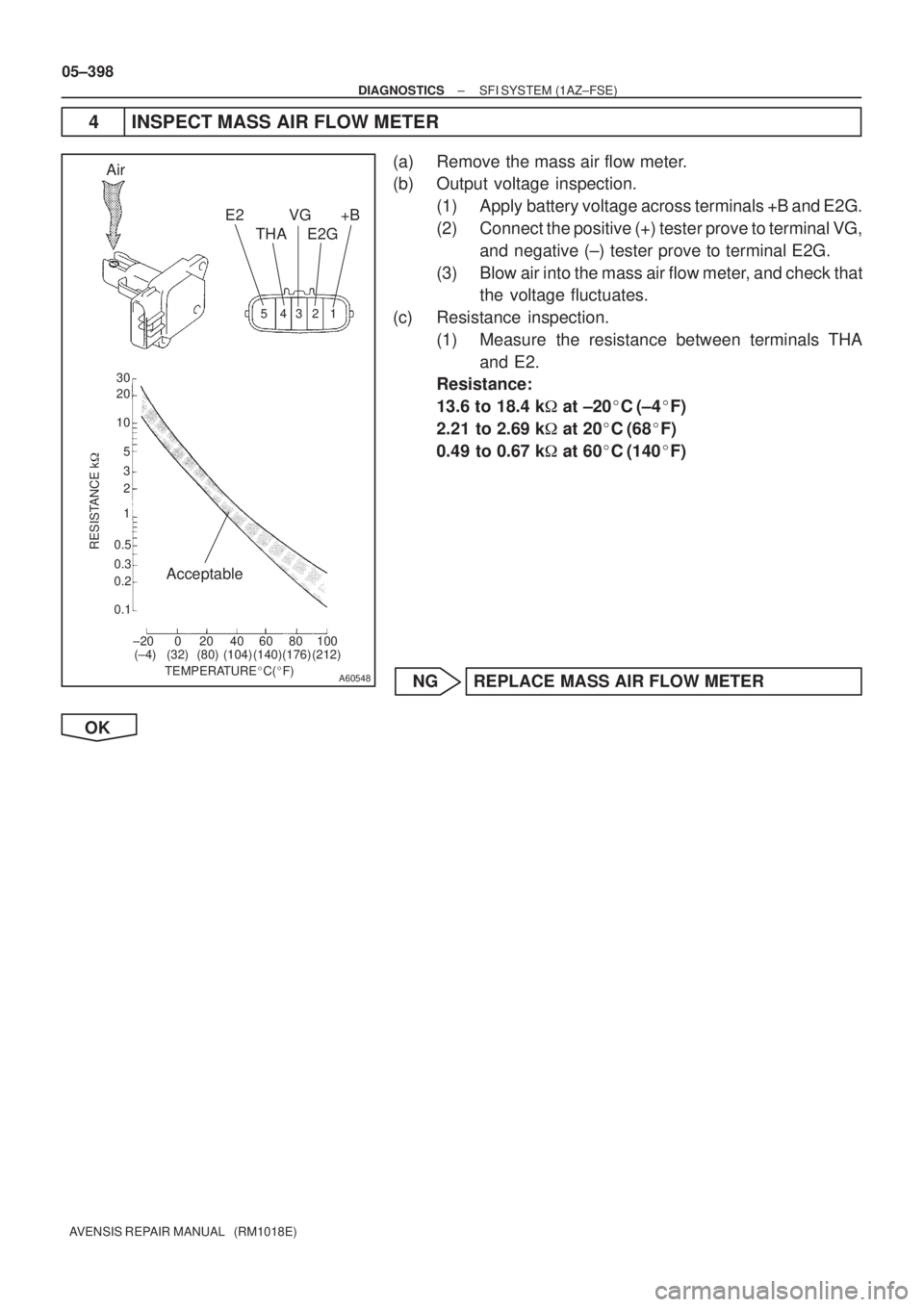
4 INSPECT MASS AIR FLOW METER
(a) Remove the mass air flow meter.
(b) Output voltage inspection.
(1) Apply battery voltage across terminals +B and E2G.
(2) Connect the positive (+) tester prove to terminal VG,
and negative (±) tester prove to terminal E2G.
(3) Blow air into the mass air flow meter, and check that
the voltage fluctuates.
(c) Resistance inspection.
(1) Measure the resistance between terminals THA
and E2.
Resistance:
13.6 to 18.4 k� at ±20�C (±4�F)
2.21 to 2.69 k� at 20�C (68�F)
0.49 to 0.67 k� at 60�C (140�F)
NG REPLACE MASS AIR FLOW METER
OK
Page 534 of 5135
(104)(140)(176) (32)(68)(212)������������
30
20
10
5
3
02040
0.1 1
0.3 0.2
0.5 2
6080100
±20
(±4)(104)(140)(176) (32)(68)(212)
A8")
������������
3020
10
5
3
02040
0.1 1
0.3 0.2
0.5 2
6080100
±20
(±4)(104)(140)(176) (32)(68)(212)������������
30
20
10
5
3
02040
0.1 1
0.3 0.2
0.5 2
6080100
±20
(±4)(104)(140)(176) (32)(68)(212)
A81700
Ohmmeter
Acceptable
TEMPERATURE �C ( �F)
RESISTANCE K �
±
DIAGNOSTICS SFI SYSTEM(1AZ±FSE)
05±399
AVENSIS REPAIR MANUAL (RM1018E)
5INSPECT ENGINE COOLANT TEMPERATURE SENSOR(RESISTANCE)
(a)Remove the engine coolant temperature sensor.
(b)Measure the resistance between the terminals.
Resistance:
2.32 to 2.59 k �at 20 �C (68 �F)
0.310 to 0.326 k �at 80 �C (176 �F)
NOTICE:
In case of checking the engine coolant temperature sensor
in the water, be careful not to allow water to go into the ter-
minals. After checking, dry the sensor.
HINT:
Alternate procedure: Connect an ohmmeter to the installed en-
gine coolant temperature sensor and read the resistance. Use
an infrared thermometer to measure the engine temperature in
the immediate vicinity of the sensor. Compare these values to
the resistance/temperature graph. Change the engine temper-
ature (warm up or allow to cool down) and repeat the test.
NGREPLACE ENGINE COOLANT TEMPERATURE SENSOR
OK
6CHECK FOR SPARK AND IGNITION (See page 18±12)
NG REPAIR OR REPLACE
OK
7CHECK FUEL PRESSURE(LOW PRESSURE) (See page 11±33)
NG CHECK AND REPLACE FUEL PUMP, PRESSURE REGULATOR, FUEL PIPE LINE AND
FILTER
OK
8CHECK FUEL PRESSURE(HIGH PRESSURE) (See page 11±33)
NG CHECK AND REPLACE FUEL PUMP, FUEL PRESSURE SENSOR, WIRING AND FUEL
LEAKAGE
OK
Page 535 of 5135

AVENSIS REPAIR MANUAL (RM1018E)
9CHECK FOR EXHAUST GAS LEAKAGE
NGREPAIR OR REPLACE EXHAUST GAS LEAKAGE POINT (See page 15±6)
OK
10 CONFIRM IF ANY MISFIRI")
05±400
±
DIAGNOSTICS SFI SYSTEM(1AZ±FSE)
AVENSIS REPAIR MANUAL (RM1018E)
9CHECK FOR EXHAUST GAS LEAKAGE
NGREPAIR OR REPLACE EXHAUST GAS LEAKAGE POINT (See page 15±6)
OK
10 CONFIRM IF ANY MISFIRING DTCS WERE PRESENT AT STEP 1
(a) Misfiring DTC ºP0301, P0302, P0303 and/or P0304º was present at st\
ep 1. NO Go to step 14
YES
11REPLACE FUEL INJECTOR ASSY (See page 11±42)
HINT:
If one or more the misfiring DTCs ºP0301, P0302, P0303 and/or P0304º\
were present at step 1, replace the
injector(s) mounted on the misfiring cylinder(s) that is referred by the DTC(s)\
with normal injector(s). GO
12PERFORM CONFIRMATION DRIVING PATTERN (See page 05±363)
HINT:
Clear all DTCs prior to performing the confirmation driving pattern.GO
13 READ OUTPUT DTC(DTC P0171, P0172, P0174 AND/OR P0175 ARE OUTPUT AGAIN)
(a) Read the DTC using the hand±held tester.
Result:
Display (DTC output)Proceed to
DTC ºP0171, P0172, P0174 and/or P0175º are output againA
DTC ºP0171, P0172, P0174 and/or P0175º are not output againB
B REPLACE FUEL INJECTOR ASSY
A
Page 536 of 5135

05±401
AVENSIS REPAIR MANUAL (RM1018E)
14READ VALUE OF HAND±HELD TESTER(OUTPUT VOLTAGE OF HEATED OXYGEN
SENSOR (BANK 1, 2 SENSOR 1))
(a)Warm up the heate")
P18349
±
DIAGNOSTICS SFI SYSTEM(1AZ±FSE)
05±401
AVENSIS REPAIR MANUAL (RM1018E)
14READ VALUE OF HAND±HELD TESTER(OUTPUT VOLTAGE OF HEATED OXYGEN
SENSOR (BANK 1, 2 SENSOR 1))
(a)Warm up the heated oxygen sensor (sensor 1) with the engine speed at 2,\
500 rpm for approximately
90 seconds.
(b)Read the output voltage of the heated oxygen sensor (sensor 1) during \
idling. The output voltage of heated oxygen sensor (sensor 1):
Alternates repeatedly between less than 0.4 V and more than 0.55 V (See the follo\
wing table).
NGGo to step 21
OK
15PERFORM CONFIRMATION DRIVING PATTERN (See page 05±363)
HINT:
Clear all DTCs prior to performing the confirmation driving pattern. GO
16 READ OUTPUT DTC(DTC P0171, P0172, P0174 AND/OR P0175 ARE OUTPUT AGAIN)
(a) Read the DTC using the hand±held tester.
Result:
Display (DTC output)Proceed to
DTC ºP0171, P0172, P0174 and/or P0175º are output againA
DTC ºP0171, P0172, P0174 and/or P0175º are not output againB
B Go to step 20
A
17 REPLACE HEATED OXYGEN SENSOR
GO
Page 537 of 5135
05±402
±
DIAGNOSTICS SFI SYSTEM(1AZ±FSE)
AVENSIS REPAIR MANUAL (RM1018E)
18PERFORM CONFIRMATION DRIVING PATTERN (See page 05±363)
HINT:
Clear all DTCs prior to performing the confirmation driving pattern. GO
19READ OUTPUT DTC(DTC P0171, P0172, P0174 AND/OR P0175 ARE OUTPUT AGAIN)
(a)Read the DTC using the hand±held tester.
Result:
Display (DTC output)Proceed to
DTC ºP0171, P0172, P0174 and/or P0175º are not output againA
DTC ºP0171, P0172, P0174 and/or P0175º are output againB
BCHECK AND REPLACE ECM (See page 01±32) AND PERFORM CONFIRMATION DRIV-
ING PATTERN (See page 05±363)
A
20 CONFIRM IF VEHICLE HAS RUN OUT OF FUEL IN PAST
NO CHECK FOR INTERMITTENT PROBLEMS
YES
DTC IS CAUSED BY RUNNING OUT OF FUEL (DTCS P0171, P0172, P0174 AND/OR P\
0175)

05±397
AVENSIS REPAIR MANUAL (RM1018E)
1CHECK OTHER DTC OUTPUT(IN ADDITION TO DTC P0171, P0172, P0174
AND/OR P0175)
(a)Read the DTC using the hand±held tester.")

AVENSIS REPAIR MANUAL (RM1018E)
18PERFORM CONFIRMATION DRIVING PATTERN (See page 05±363)
HINT:
Clear all DTCs prior to performing the confirmation drivin")