Page 853 of 5135
± DIAGNOSTICSABS WITH EBD & BA & TRC & VSC SYSTEM
05±805
AVENSIS REPAIR MANUAL (RM1018E)
DTC C1225/25 SMC SOLENOID CIRCUIT
DTC C1226/26 SMC SOLENOID CIRCUIT
DTC C1227/27 SRC SOLENOID CIRCUIT
DTC C1228/28 SRC SOLENOID CIRCUIT
CIRCUIT DESCRIPTION
The solenoid goes on when receiving signals from the ECU and controls the pressure action on the wheel
cylinders to control the braking force.
DTC No.DTC Detecting ConditionTrouble Area
C1225/25Open or short in SMC1 circuit.�Brake actuator
�SMC1 circuit
C1226/26Open or short in SMC2 circuit.�Brake actuator
�SMC2 circuit
C1227/27Open or short in SRC1 circuit.�Brake actuator
�SRC1 circuit
C1228/28Open or short in SRC2 circuit.�Brake actuator
�SRC2 circuit
05785±02
Page 854 of 5135
F45132
Battery
FL MAIN Skid Control ECU
with Actuator
B±G (*1)L (*1) 1
ALT
Engine Room R/B No.4 & Engine Room J/B No.4
1
4B
W±BS1
S1 10
9
+BM
12
1
2
GND1 GND2
S1 6
W±B W±B
*1: 1AZ±FSE
*2: 1CD±FTV EA4
L (*2)
W (*2)
2
12
331
1B1
VSC
ALT
Engine Room R/B No.3
Engine Room R/B No.1 &
Engine Room J/B No.1
B (*2)
B±G (*1) VSC
05±806
±
DIAGNOSTICS ABS WITH EBD & BA & TRC & VSC SYSTEM
AVENSIS REPAIR MANUAL (RM1018E)
WIRING DIAGRAM
INSPECTION PROCEDURE
1RECONFIRM DTC
(a)Check if other DTCs are detected (See page 05±756). YES REPAIR CIRCUIT INDICATED BY OUTPUTCODE
NO
REPLACE ABS & TRACTION ACTUATOR ASSY(See page 32±57)
Page 855 of 5135
± DIAGNOSTICSABS WITH EBD & BA & TRC & VSC SYSTEM
05±801
AVENSIS REPAIR MANUAL (RM1018E)
DTC C1208/54 MALFUNCTION IN STEERING ANGLE
SENSOR CIRCUIT
CIRCUIT DESCRIPTION
DTC No.DTC Detecting ConditionTrouble Area
C1231/31
Detection of any of conditions 1 through 7:
1. When the condition that ECU terminal IG1 voltage is 9.8
V or more, and does not receive data from steering
angle sensor continues.
2. Sensor internal failure.
3. The offset value is out of range.
4. Sensor signal changes too rapidly.
5. Steering angle value difference between measured and
reference is out of range.
6. Steering sensor is not centered.
7. Steering sensor signal is out of range.
8. Steering sensor is not calibrated.
�Steering angle sensor
�Steering angle sensor circuit
05C5R±01
Page 858 of 5135

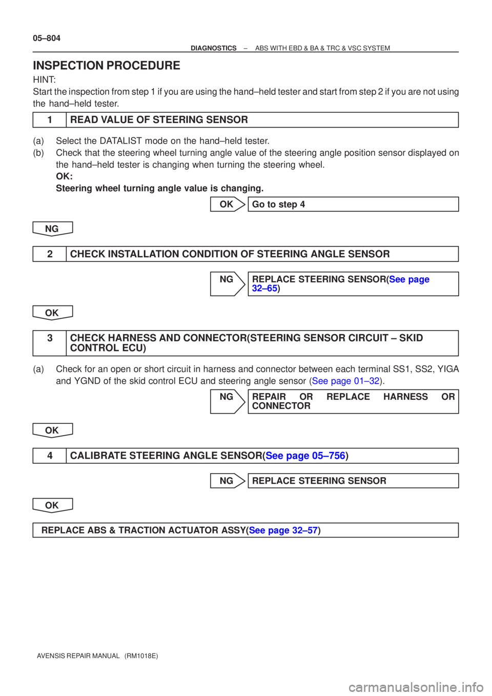
05±804
±
DIAGNOSTICS ABS WITH EBD & BA & TRC & VSC SYSTEM
AVENSIS REPAIR MANUAL (RM1018E)
INSPECTION PROCEDURE
HINT:
Start the inspection from step 1 if you are using the hand±held tester and\
start from step 2 if you are not using
the hand±held tester.
1READ VALUE OF STEERING SENSOR
(a)Select the DATALIST mode on the hand±held tester.
(b)Check that the steering wheel turning angle value of the steering angle position sensor displayed on the hand±held tester is changing when turning the steering wheel.
OK:
Steering wheel turning angle value is changing.
OKGo to step 4
NG
2CHECK INSTALLATION CONDITION OF STEERING ANGLE SENSOR
NGREPLACE STEERING SENSOR(See page 32±65)
OK
3 CHECK HARNESS AND CONNECTOR(STEERING SENSOR CIRCUIT ± SKID CONTROL ECU)
(a) Check for an open or short circuit in harness and connector between each term\
inal SS1, SS2, YIGA
and YGND of the skid control ECU and steering angle sensor (See page 01±32).
NG REPAIR OR REPLACE HARNESS ORCONNECTOR
OK
4CALIBRATE STEERING ANGLE SENSOR(See page 05±756)
NG REPLACE STEERING SENSOR
OK
REPLACE ABS & TRACTION ACTUATOR ASSY(See page 32±57)
Page 859 of 5135

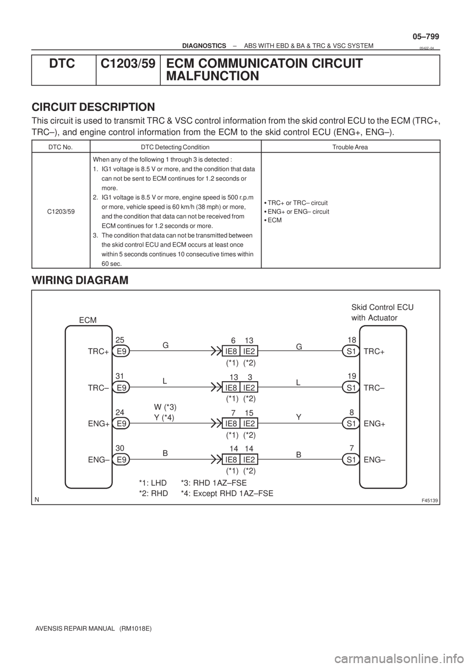
F45139
Skid Control ECU
with Actuator
S118
*1: LHD
*2: RHDG
TRC+ E925
IE86
IE213
(*1) (*2) ECM
E9 31
E9 24
E9 30 TRC±
ENG+
ENG±
*3: RHD 1AZ±FSE
*4: Except RHD 1AZ±FSEIE813
IE23
(*1) (*2)
IE87
IE215
(*1) (*2)
IE814
IE214
(*1) (*2) L
W (*3)
Y (*4)
BG
L
Y
BS1
S1
S17 8 19TRC+
TRC±
ENG+
ENG±
± DIAGNOSTICSABS WITH EBD & BA & TRC & VSC SYSTEM
05±799
AVENSIS REPAIR MANUAL (RM1018E)
DTC C1203/59 ECM COMMUNICATOIN CIRCUIT
MALFUNCTION
CIRCUIT DESCRIPTION
This circuit is used to transmit TRC & VSC control information from the skid control ECU to the ECM (TRC+,
TRC±), and engine control information from the ECM to the skid control ECU (ENG+, ENG±).
DTC No.DTC Detecting ConditionTrouble Area
C1203/59
When any of the following 1 through 3 is detected :
1. IG1 voltage is 8.5 V or more, and the condition that data
can not be sent to ECM continues for 1.2 seconds or
more.
2. IG1 voltage is 8.5 V or more, engine speed is 500 r.p.m
or more, vehicle speed is 60 km/h (38 mph) or more,
and the condition that data can not be received from
ECM continues for 1.2 seconds or more.
3. The condition that data can not be transmitted between
the skid control ECU and ECM occurs at least once
within 5 seconds continues 10 consecutive times within
60 sec.
�TRC+ or TRC± circuit
�ENG+ or ENG± circuit
�ECM
WIRING DIAGRAM
0542Z±04
Page 860 of 5135
05±800
±
DIAGNOSTICS ABS WITH EBD & BA & TRC & VSC SYSTEM
AVENSIS REPAIR MANUAL (RM1018E)
INSPECTION PROCEDURE
1CHECK HARNESS AND CONNECTOR(ECM ± SKID CONTROL ECU)
(a)Check for an open or short circuit in harness and connector between each of t\
erminals ENG+, ENG±, TRC+, TRC± of the skid control ECU and the same one of the ECM (See page 01±32).
NG REPAIR OR REPLACE HARNESS ORCONNECTOR
OK
2 CHECK OPERATION OF MALFUNCTION INDICATOR
(a) Check the MIL. (1) The MIL comes on when the ignition switch is turned ON and the engine is\
not running.
NG CHECK AND REPLACE ECM
OK
CHECK AND REPLACE ABS & TRACTION ACTUATOR ASSY(See page 32±57)
Page 861 of 5135
F45138
Skid Control ECU
with ActuatorNEO
S1 32
Y±B
*1: LHD
*2: RHD Y±B
NEOE9 17
IE85
IE113
(*1)(*2)
ECM
±
DIAGNOSTICS ABS WITH EBD & BA & TRC & VSC SYSTEM
05±797
AVENSIS REPAIR MANUAL (RM1018E)
DTCC1204/44NE SIGNAL CIRCUIT
CIRCUIT DESCRIPTION
The skid control ECU receives engine revolution speed signals (NE signals)\
from the ECM.
DTC No.DTC Detecting ConditionTrouble Area
C1202/44
At vehicle speed of 30 km/h (19 mph) or more, when data
received from the ECM is in normal condition, engine revo-
lution signal > 0 rpm continues for 5 seconds or more.�NEO circuit
� ECM
� Skid control ECU
WIRING DIAGRAM
INSPECTION PROCEDURE
1CHECK HARNESS AND CONNECTOR(SKID CONTROL ECU ± ECM)
(a)Check for an open or short circuit in harness and connector between terminal \
NEO of the skid control
ECU and ECM (See page 01±32).
NG REPAIR OR REPLACE HARNESS ORCONNECTOR
OK
05432±04
Page 863 of 5135
05±796
± DIAGNOSTICSABS WITH EBD & BA & TRC & VSC SYSTEM
AVENSIS REPAIR MANUAL (RM1018E)
DTC C1201/45 ENGINE CONTROL SYSTEM MALFUNCTION
CIRCUIT DESCRIPTION
DTC No.DTC Detecting ConditionTrouble Area
C1201/45A trouble signal in the engine control system is input.Engine control system
HINT:
If trouble occurs in the engine control system, the ECU prohibits TRC and VSC control.
INSPECTION PROCEDURE
1 CHECK DTC FOR ENGINE
ANormal Code
BMalfunction Code
B REPAIR ENGINE CONTROL SYSTEM
ACCORDING TO CODE OUTPUT
A
REPLACE ECM
05C5O±01