Page 878 of 5135

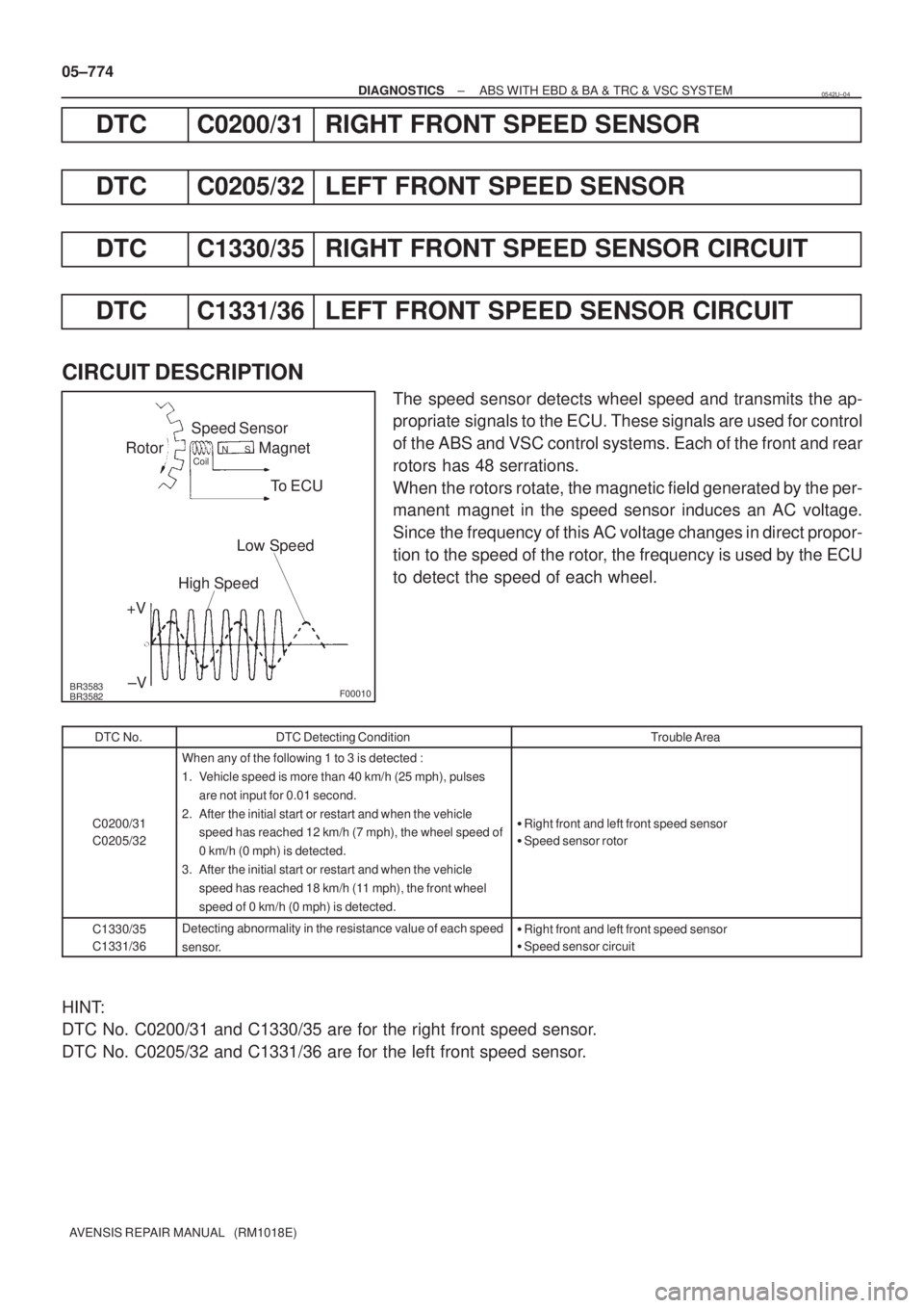
BR3583
BR3582F00010
Rotor
+VSpeed Sensor
MagnetCoilNS
To ECU
Low Speed
High Speed
±V 05±774
± DIAGNOSTICSABS WITH EBD & BA & TRC & VSC SYSTEM
AVENSIS REPAIR MANUAL (RM1018E)
DTC C0200/31 RIGHT FRONT SPEED SENSOR
DTC C0205/32 LEFT FRONT SPEED SENSOR
DTC C1330/35 RIGHT FRONT SPEED SENSOR CIRCUIT
DTC C1331/36 LEFT FRONT SPEED SENSOR CIRCUIT
CIRCUIT DESCRIPTION
The speed sensor detects wheel speed and transmits the ap-
propriate signals to the ECU. These signals are used for control
of the ABS and VSC control systems. Each of the front and rear
rotors has 48 serrations.
When the rotors rotate, the magnetic field generated by the per-
manent magnet in the speed sensor induces an AC voltage.
Since the frequency of this AC voltage changes in direct propor-
tion to the speed of the rotor, the frequency is used by the ECU
to detect the speed of each wheel.
DTC No.DTC Detecting ConditionTrouble Area
C0200/31
C0205/32
When any of the following 1 to 3 is detected :
1. Vehicle speed is more than 40 km/h (25 mph), pulses
are not input for 0.01 second.
2. After the initial start or restart and when the vehicle
speed has reached 12 km/h (7 mph), the wheel speed of
0 km/h (0 mph) is detected.
3. After the initial start or restart and when the vehicle
speed has reached 18 km/h (11 mph), the front wheel
speed of 0 km/h (0 mph) is detected.
�Right front and left front speed sensor
�Speed sensor rotor
C1330/35
C1331/36Detecting abnormality in the resistance value of each speed
sensor.�Right front and left front speed sensor
�Speed sensor circuit
HINT:
DTC No. C0200/31 and C1330/35 are for the right front speed sensor.
DTC No. C0205/32 and C1331/36 are for the left front speed sensor.
0542U±04
Page 880 of 5135

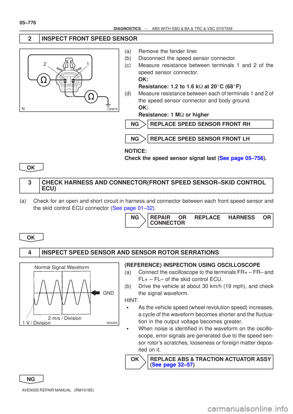
C93876
21
W04200
Normal Signal Waveform
1 V / Division 2 m/s / Division GND
05±776
±
DIAGNOSTICS ABS WITH EBD & BA & TRC & VSC SYSTEM
AVENSIS REPAIR MANUAL (RM1018E)
2INSPECT FRONT SPEED SENSOR
(a)Remove the fender liner.
(b)Disconnect the speed sensor connector.
(c)Measure resistance between terminals 1 and 2 of the speed sensor connector.
OK:
Resistance: 1.2 to 1.6 k �at 20 �C (68 �F)
(d)Measure resistance between each of terminals 1 and 2 of
the speed sensor connector and body ground.
OK:
Resistance: 1 M � or higher
NGREPLACE SPEED SENSOR FRONT RH
NGREPLACE SPEED SENSOR FRONT LH
NOTICE:
Check the speed sensor signal last (See page 05±756).
OK
3CHECK HARNESS AND CONNECTOR(FRONT SPEED SENSOR±SKID CONTROL ECU)
(a)Check for an open and short circuit in harness and connector between each fro\
nt speed sensor and
the skid control ECU connector (See page 01±32).
NGREPAIR OR REPLACE HARNESS ORCONNECTOR
OK
4INSPECT SPEED SENSOR AND SENSOR ROTOR SERRATIONS
(REFERENCE) INSPECTION USING OSCILLOSCOPE
(a)Connect the oscilloscope to the terminals FR+ ± FR± and FL+ ± FL± of the skid control ECU.
(b)Drive the vehicle at about 30 km/h (19 mph), and check
the signal waveform.
HINT:
�As the vehicle speed (wheel revolution speed) increases,
a cycle of the waveform becomes shorter and the fluctua-
tion in the output voltage becomes greater.
�When noise is identified in the waveform on the oscillo-
scope, error signals are generated due to the speed sen-
sor rotor's scratches, looseness or foreign matter depos-
ited on it.
OKREPLACE ABS & TRACTION ACTUATOR ASSY (See page 32±57)
NG
Page 882 of 5135

0542T±04
05±772
±
DIAGNOSTICS ABS WITH EBD & BA & TRC & VSC SYSTEM
AVENSIS REPAIR MANUAL (RM1018E)
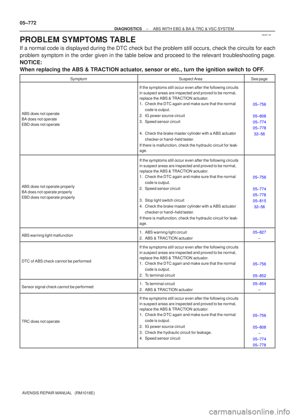
PROBLEM SYMPTOMS TABLE
If a normal code is displayed during the DTC check but the problem still o\
ccurs, check the circuits for each
problem symptom in the order given in the table below and proceed to the releva\
nt troubleshooting page.
NOTICE:
When replacing the ABS & TRACTION actuator, sensor or etc., turn the ignition switch to OFF.
SymptomSuspect AreaSee page
ABS does not operate
BA does not operate
EBD does not operate
If the symptoms still occur even after the following circuits
in suspect areas are inspected and proved to be normal,
replace the ABS & TRACTION actuator.
1. Check the DTC again and make sure that the normal code is output.
2. IG power source circuit
3. Speed sensor circuit
4. Check the brake master cylinder with a ABS actuator checker or hand±held tester.
If there is malfunction, check the hydraulic circuit for leak-
age.
05±756
05±808
05±774
05±778 32±56
ABS does not operate properly
BA does not operate properly
EBD does not operate properly
If the symptoms still occur even after the following circuits
in suspect areas are inspected and proved to be normal,
replace the ABS & TRACTION actuator.
1. Check the DTC again and make sure that the normal code is output.
2. Speed sensor circuit
3. Stop light switch circuit
4. Check the brake master cylinder with a ABS actuator checker or hand±held tester.
If there is malfunction, check the hydraulic circuit for leak-
age.
05±756
05±774
05±778
05±815 32±56
ABS warning light malfunction1. ABS warning light circuit
2. ABS & TRACTION actuator05±827 ±
DTC of ABS check cannot be performed
If the symptoms still occur even after the following circuits
in suspect areas are inspected and proved to be normal,
replace the ABS & TRACTION actuator.
1. Check the DTC again and make sure that the normal code is output.
2. Tc terminal circuit
05±756
05±852
Sensor signal check cannot be performed1. Ts terminal circuit
2. ABS & TRACTION actuator05±854 ±
TRC does not operate
If the symptoms still occur even after the following circuits
in suspect areas are inspected and proved to be normal,
replace the ABS & TRACTION actuator.
1. Check the DTC again and make sure that the normal code is output.
2. IG power source circuit
3. Check the hydraulic circuit for leakage.
4. Speed sensor circuit
05±756
05±808 ±
05±774
05±778
Page 883 of 5135

±
DIAGNOSTICS ABS WITH EBD & BA & TRC & VSC SYSTEM
05±773
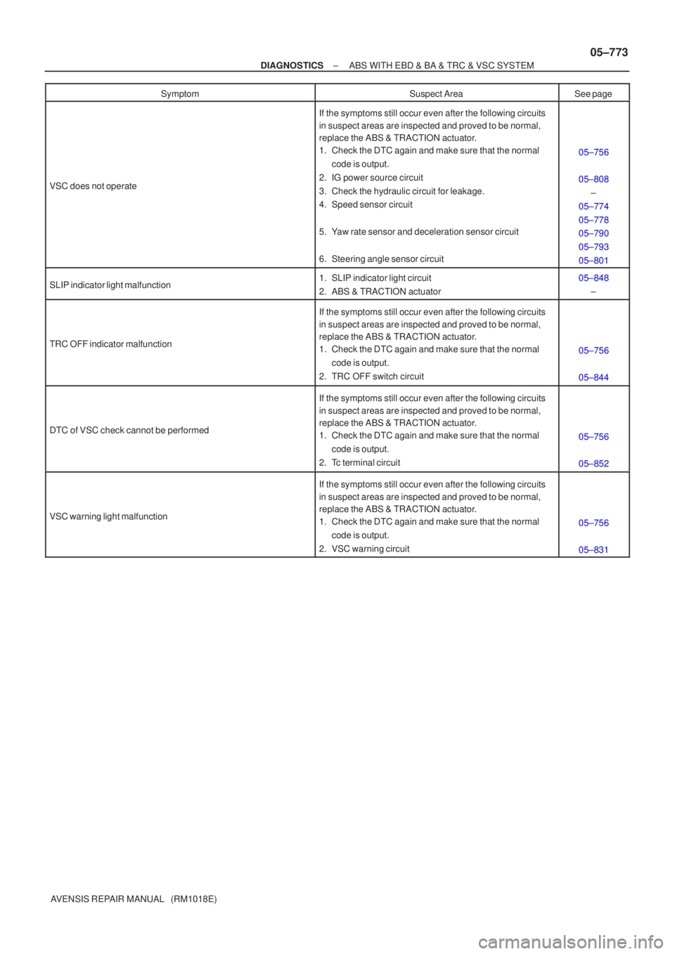
AVENSIS REPAIR MANUAL (RM1018E) Symptom
Suspect AreaSee page
VSC does not operate
If the symptoms still occur even after the following circuits
in suspect areas are inspected and proved to be normal,
replace the ABS & TRACTION actuator.
1. Check the DTC again and make sure that the normal
code is output.
2. IG power source circuit
3. Check the hydraulic circuit for leakage.
4. Speed sensor circuit
5. Yaw rate sensor and deceleration sensor circuit
6. Steering angle sensor circuit
05±756
05±808 ±
05±774
05±778
05±790
05±793
05±801
SLIP indicator light malfunction1. SLIP indicator light circuit
2. ABS & TRACTION actuator05±848 ±
TRC OFF indicator malfunction
If the symptoms still occur even after the following circuits
in suspect areas are inspected and proved to be normal,
replace the ABS & TRACTION actuator.
1. Check the DTC again and make sure that the normal code is output.
2. TRC OFF switch circuit
05±756
05±844
DTC of VSC check cannot be performed
If the symptoms still occur even after the following circuits
in suspect areas are inspected and proved to be normal,
replace the ABS & TRACTION actuator.
1. Check the DTC again and make sure that the normal code is output.
2. Tc terminal circuit
05±756
05±852
VSC warning light malfunction
If the symptoms still occur even after the following circuits
in suspect areas are inspected and proved to be normal,
replace the ABS & TRACTION actuator.
1. Check the DTC again and make sure that the normal code is output.
2. VSC warning circuit
05±756
05±831
Page 886 of 5135
F45132
Battery FL MAINSkid Control ECU
with Actuator
B±G (*1) L (*1)
1 ALT Engine Room R/B No.4 & Engine Room J/B No.4
1
4B
W±BS1
S1 109
+BM
12
1 2
GND1 GND2
S16
W±BW±B
*1: 1AZ±FSE
*2: 1CD±FTVEA4
L (*2)
W (*2)
2 12 33 11B1VSC
ALT Engine Room R/B No.3Engine Room R/B No.1 &
Engine Room J/B No.1
B (*2)
B±G (*1)VSC
± DIAGNOSTICSABS WITH EBD & BA & TRC & VSC SYSTEM
05±825
AVENSIS REPAIR MANUAL (RM1018E)
DTC C1350/51 PUMP MOTOR IS LOCKED/OPEN CIRCUIT
IN PUMP MOTOR GROUND
CIRCUIT DESCRIPTION
DTC No.DTC Detecting ConditionTrouble Area
C1350/51
When any of the following 1 through 3 is detected.
1. No motor voltage supply within 0.08 sec. after actuation
starts the motor relay.
2. A high level of motor voltage when actuation does not
starts the motor relay for more than 2.5 sec.
3. The pump motor voltage is high level for a certain time
after the motor relay has elapsed.
�Brake actuator pump motor
�ABS motor relay circuit
WIRING DIAGRAM
0578A±02
Page 887 of 5135
05±826
±
DIAGNOSTICS ABS WITH EBD & BA & TRC & VSC SYSTEM
AVENSIS REPAIR MANUAL (RM1018E)
INSPECTION PROCEDURE
1RECONFIRM DTC
(a)Check if other DTCs are detected (See page 05±756). YES REPAIR CIRCUIT INDICATED BY OUTPUTCODE
NO
REPLACE ABS & TRACTION ACTUATOR ASSY(See page 32±57)
Page 888 of 5135
± DIAGNOSTICSABS WITH EBD & BA & TRC & VSC SYSTEM
05±821
AVENSIS REPAIR MANUAL (RM1018E)
DTC C1301/42 CAN COMMUNICATION SYSTEM
MALFUNCTION
CIRCUIT DESCRIPTION
This circuit is used to send TRC & VSC control information from the yaw rate sensor and steering angle sen-
sor information to the skid control ECU
DTC No.DTC Detecting ConditionTrouble Area
C1301/42
IG1 voltage is 9.5 V or more, and the condition that data
from steering angle sensor or yaw rate sensor can not be
received continues for 0.1 seconds or more.�Yaw rate sensor
�Steering angle sensor
�Yaw rate sensor circuit
�Steering angle sensor circuit
05C5U±01
Page 891 of 5135
05±824
±
DIAGNOSTICS ABS WITH EBD & BA & TRC & VSC SYSTEM
AVENSIS REPAIR MANUAL (RM1018E)
INSPECTION PROCEDURE
1CHECK HARNESS AND CONNECTOR(YAW RATE SENSOR ± SKID CONTROL ECU)
(a)Check for an open or short circuit in harness and connector between the \
yaw rate sensor and skid
control ECU (See page 01±32).
NG REPAIR OR REPLACE HARNESS ORCONNECTOR
OK
2 CHECK HARNESS AND CONNECTOR(STEERING ANGLE SENSOR ± SKID CONTROL ECU)
(a) Check for an open or short circuit in harness and connector between the steer\
ing angle sensor and
skid control ECU (See page 01±32).
NG REPAIR OR REPLACE HARNESS ORCONNECTOR
OK
REPLACE ABS & TRACTION ACTUATOR ASSY(See page 32±57)