Page 3060 of 5135
610EB±01
A79910N�m (kgf�cm ft�lbf): Specified torqueRear Window Side
Garnish RH
Roof Side
Garnish Inner RH
Deck Trim
Side Board RH
Deck Floor
Box RH
Deck Floor
Box Front
Tonneau Cover Assy
Deck Board
Sub±assy
Deck Floor
Box Rear
Deck Trim
Side Board LH
Deck Floor
Box LH
Rear Window
Side Garnish
LH
Roof Side
Garnish
Inner LHRear Floor
Finish Plate
Rear Seat Cushion Assy
and Rear Seatback Assy
Rear Seat
3 Point Type
Belt Assy Inner
42 (430, 31)
Rear Seat
3 Point Type
Belt Assy Outer
Rear Seat Belt
Assy Outer Center
Rear Seat
3 Point Type
Belt Assy Inner
31 (316, 23)CRS Anchor
Bracket Sub±assy
7.5 (76.5, 66 in.�lbf)
42 (430, 31)
42 (430, 31)
42 (430, 31)
± SEAT BELTREAR SEAT BELT (WAGON MODELS)
61±23
AVENSIS REPAIR MANUAL (RM1018E)
REAR SEAT BELT (WAGON MODELS)
COMPONENTS
Page 3072 of 5135

B51763
SST
SST
B50513
10 m or more
±
SEAT BELT FRONT SEAT BELT
61±11
AVENSIS REPAIR MANUAL (RM1018E)
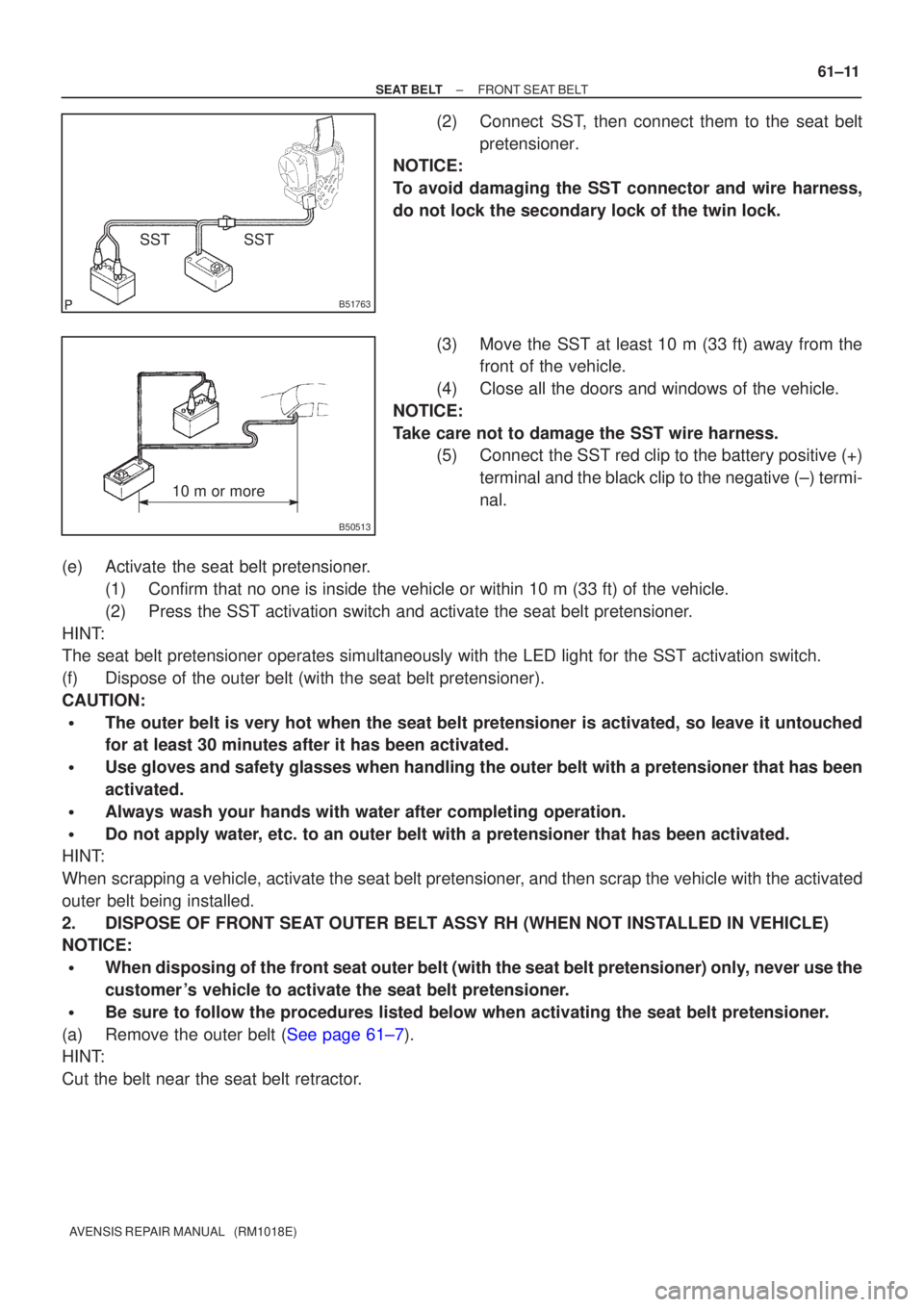
(2) Connect SST, then connect them to the seat belt
pretensioner.
NOTICE:
To avoid damaging the SST connector and wire harness,
do not lock the secondary lock of the twin lock.
(3) Move the SST at least 10 m (33 ft) away from thefront of the vehicle.
(4) Close all the doors and windows of the vehicle.
NOTICE:
Take care not to damage the SST wire harness. (5) Connect the SST red clip to the battery positive (+)
terminal and the black clip to the negative (±) termi-
nal.
(e) Activate the seat belt pretensioner. (1) Confirm that no one is inside the vehicle or within 10 m (33 ft) of th\
e vehicle.
(2) Press the SST activation switch and activate the seat belt pretensioner.
HINT:
The seat belt pretensioner operates simultaneously with the LED light fo\
r the SST activation switch.
(f) Dispose of the outer belt (with the seat belt pretensioner).
CAUTION:
�The outer belt is very hot when the seat belt pretensioner is activated,\
so leave it untouched
for at least 30 minutes after it has been activated.
�Use gloves and safety glasses when handling the outer belt with a pretensio\
ner that has been
activated.
�Always wash your hands with water after completing operation.
�Do not apply water, etc. to an outer belt with a pretensioner that has been activated.
HINT:
When scrapping a vehicle, activate the seat belt pretensioner, and then scrap the vehicle with the activated
outer belt being installed.
2. DISPOSE OF FRONT SEAT OUTER BELT ASSY RH (WHEN NOT INSTALLED IN VEHICLE)
NOTICE:
�When disposing of the front seat outer belt (with the seat belt pretens\
ioner) only, never use the
customer 's vehicle to activate the seat belt pretensioner.
�Be sure to follow the procedures listed below when activating the seat b\
elt pretensioner.
(a)Remove the outer belt (See page 61±7).
HINT:
Cut the belt near the seat belt retractor.
Page 3118 of 5135
670SB±01
I36707
±
AUDIO & VISUAL SYSTEM REAR SPEAKER ASSY NO.2
67±15
AVENSIS REPAIR MANUAL (RM1018E)
REAR SPEAKER ASSY NO.2
REPLACEMENT
1. REMOVE REAR DOOR WINDOW REGULATOR HANDLE ASSY (W/O POWER WINDOW)
(See page 75±22)
2. REMOVE POWER WINDOW REGULATOR SWITCH ASSY REAR (W/ POWER WINDOW) (See page 75±22)
3.REMOVE REAR DOOR TRIM BASE LH (See page 75±22)
4.REMOVE REAR DOOR TRIM BOARD SUB±ASSY LH (See page 75±22)
5. REMOVE REAR SPEAKER ASSY NO.2
(a) Disconnect the connector.
(b) Remove the screw and the rear No.2 speaker assy.
Page 3119 of 5135

670SA±01
������I35188
������I35189
(2)
(1)
(3)
H02440
Riveter
Mandrel
±
AUDIO & VISUAL SYSTEM REAR SPEAKER ASSY
67±13
AVENSIS REPAIR MANUAL (RM1018E)
REAR SPEAKER ASSY
REPLACEMENT
1.REMOVE REAR DOOR WINDOW REGULATOR HANDLE ASSY (See page 75±22)
2.REMOVE REAR DOOR TRIM BASE LH (See page 75±22)
3. REMOVE POWER WINDOW REGULATOR SWITCH ASSY REAR (W/ POWER WINDOW)
(See page 75±22)
4.REMOVE REAR DOOR TRIM BOARD SUB±ASSY LH (See page 75±22)
5. REMOVE REAR SPEAKER ASSY
(a) Disconnect the connector.
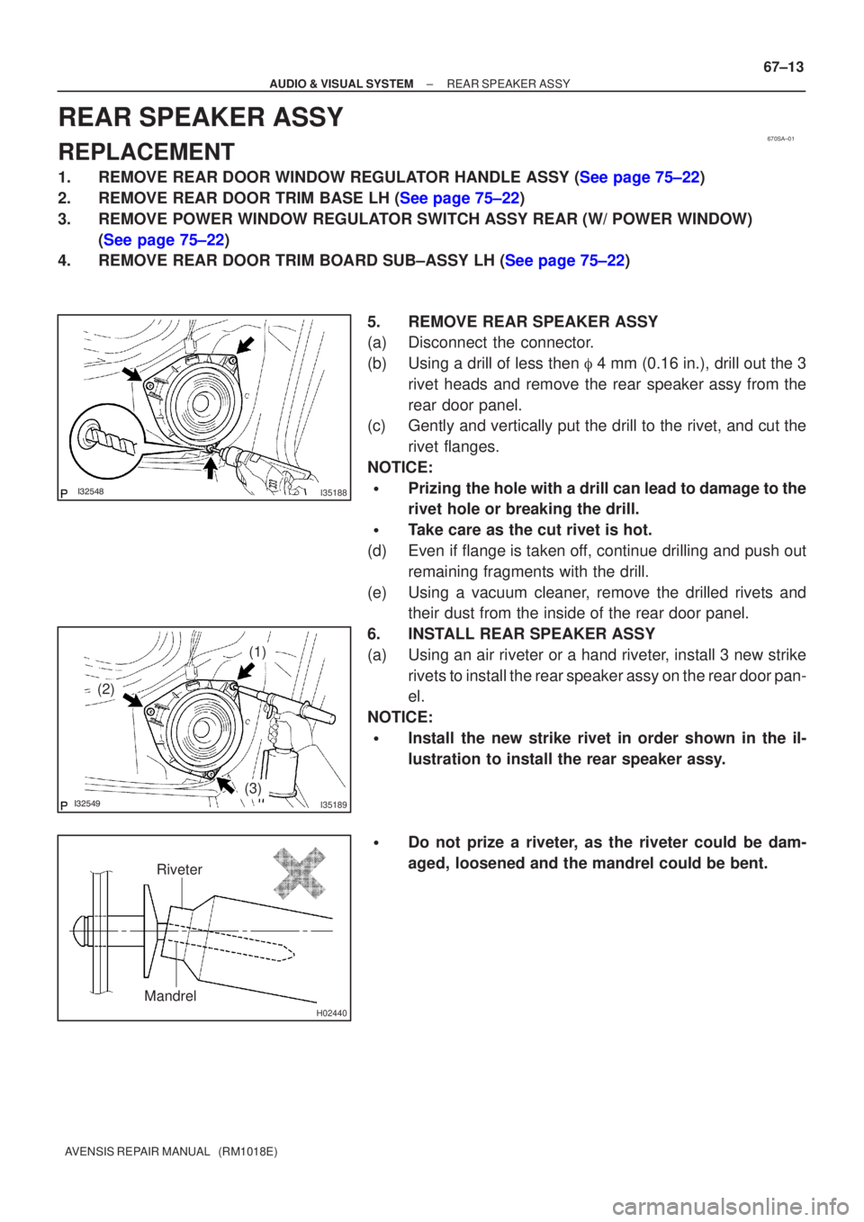
(b) Using a drill of less then � 4 mm (0.16 in.), drill out the 3
rivet heads and remove the rear speaker assy from the
rear door panel.
(c) Gently and vertically put the drill to the rivet, and cut the
rivet flanges.
NOTICE:
�Prizing the hole with a drill can lead to damage to the
rivet hole or breaking the drill.
�Take care as the cut rivet is hot.
(d) Even if flange is taken off, continue drilling and push out remaining fragments with the drill.
(e) Using a vacuum cleaner, remove the drilled rivets and their dust from the inside of the rear door panel.
6. INSTALL REAR SPEAKER ASSY
(a) Using an air riveter or a hand riveter, install 3 new strike rivets to install the rear speaker assy on the rear door pan-
el.
NOTICE:
�Install the new strike rivet in order shown in the il-
lustration to install the rear speaker assy.
�Do not prize a riveter, as the riveter could be dam-
aged, loosened and the mandrel could be bent.
Page 3122 of 5135

670S8±01
������I35168
������I35169
(2)
(1)
(3)
H02440
Riveter
Mandrel
67±10
±
AUDIO & VISUAL SYSTEM FRONT NO.1 SPEAKER ASSY
AVENSIS REPAIR MANUAL (RM1018E)
FRONT NO.1 SPEAKER ASSY
REPLACEMENT
1. REMOVE REAR DOOR WINDOW REGULATOR HANDLE ASSY (W/O POWER WINDOW) (See page 75±8)
2.REMOVE FRONT DOOR LOWER FRAME BRACKET GARNISH LH (See page 75±8)
3.REMOVE FRONT DOOR TRIM BASE LH (See page 75±8)
4.REMOVE FUEL LID OPENER SWITCH (See page 75±8)
5. REMOVE POWER WINDOW REGULATOR SWITCH ASSY (W/ POWER WINDOW) (See page 75±8)
6.REMOVE FRONT DOOR TRIM BOARD SUB±ASSY LH (See page 75±8)
7. REMOVE FRONT NO.1 SPEAKER ASSY
(a) Disconnect the connector.
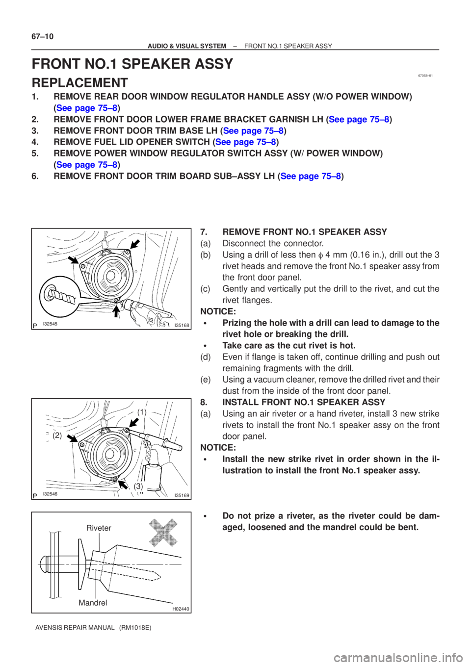
(b) Using a drill of less then � 4 mm (0.16 in.), drill out the 3
rivet heads and remove the front No.1 speaker assy from
the front door panel.
(c) Gently and vertically put the drill to the rivet, and cut the rivet flanges.
NOTICE:
�Prizing the hole with a drill can lead to damage to the
rivet hole or breaking the drill.
�Take care as the cut rivet is hot.
(d) Even if flange is taken off, continue drilling and push out remaining fragments with the drill.
(e) Using a vacuum cleaner, remove the drilled rivet and their
dust from the inside of the front door panel.
8. INSTALL FRONT NO.1 SPEAKER ASSY
(a) Using an air riveter or a hand riveter, install 3 new strike rivets to install the front No.1 speaker assy on the front
door panel.
NOTICE:
�Install the new strike rivet in order shown in the il-
lustration to install the front No.1 speaker assy.
�Do not prize a riveter, as the riveter could be dam-
aged, loosened and the mandrel could be bent.
Page 3137 of 5135
660CU±01
I35778
A: 150 mm (5.91 in.)
B: 50 mm (1.97 in.)
C: 480 mm (18.90 in.)
D: 295 mm (11.61 in.)
E: 310 mm (12.21 in.)F: 275 mm (10.83 in.)
G: 130 mm (5.12 in.)
H: 420 mm (16.54 in.)
I: 280 mm (11.02 in.) Front:
AB
C
DE
FG
HI
A
A
A
B
B
B
C 66±22
± WIPER & WASHERWASHER NOZZLE SUB±ASSY
AVENSIS REPAIR MANUAL (RM1018E)
WASHER NOZZLE SUB±ASSY
ADJUSTMENT
1. REMOVE WASHER NOZZLE SUB±ASSY
(a) With the engine running, check that the point where the washer fluid hits the windshield and the rear
window is within the range indicated by the hatched line.
Page 3147 of 5135
I34456
17.5 ± 32.5 mm
(0.69 ± 1.28 in.)
Cowl top ventilator louver
66±16
± WIPER & WASHERWINDSHIELD WIPER MOTOR ASSY
AVENSIS REPAIR MANUAL (RM1018E)
10. INSTALL FR WIPER ARM RH
(a) Scrape off the serration part of the wiper arm with a round
file or equivalent.
(b) Clean the wiper pivot serration with a wire brush.
(c) Install the front wiper arm RH with the nut to the position
shown in the illustration.
Torque: 21 N�m (210 kgf�cm, 15 ft�lbf)
HINT:
Hold down the arm hinge by hand to fasten the nut.
(d) Operate the wiper while running the water or the washer
fluid over the window, and check the wiping condition and
that the front wiper does not hit against the vehicle body.
Page 3160 of 5135

670SL±01
BE4029
Tester Probe
Tin FoilHeat Wire
E32576
BE0150
Repair Point
Masking TapeBroken
Wire
BE0151
Repair PointFine Tip Brush
Glass
± AUDIO & VISUAL SYSTEMWINDOW GLASS (ANTENNA WIRE)
67±33
AVENSIS REPAIR MANUAL (RM1018E)
WINDOW GLASS (ANTENNA WIRE)
REPAIR
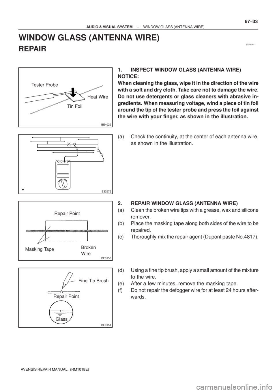
1. INSPECT WINDOW GLASS (ANTENNA WIRE)
NOTICE:
When cleaning the glass, wipe it in the direction of the wire
with a soft and dry cloth. Take care not to damage the wire.
Do not use detergents or glass cleaners with abrasive in-
gredients. When measuring voltage, wind a piece of tin foil
around the tip of the tester probe and press the foil against
the wire with your finger, as shown in the illustration.
(a) Check the continuity, at the center of each antenna wire,
as shown in the illustration.
2. REPAIR WINDOW GLASS (ANTENNA WIRE)
(a) Clean the broken wire tips with a grease, wax and silicone
remover.
(b) Place the masking tape along both sides of the wire to be
repaired.
(c) Thoroughly mix the repair agent (Dupont paste No.4817).
(d) Using a fine tip brush, apply a small amount of the mixture
to the wire.
(e) After a few minutes, remove the masking tape.
(f) Do not repair the defogger wire for at least 24 hours after-
wards.