Page 1671 of 5135
05BA8±01
������
������B68543
Rear Window Defogger
Switch AssyEngine Room R/B
� DCC Fuse
� HORN Fuse
Fuse Block
� DOME Fuse
� ECU±B2 Fuse
Center J/B
Security Indicator
Engine Room J/B No. 4*1
Engine Room R/B No. 4*1
� ALT H±fuse
Engine Room R/B No. 3*2
� ALT H±fuse
Engine Room R/B No. 2
� HORN Relay
High Pitched Horn AssyLow Pitched Horn AssyHazard Warning Light
Hazard Warning Light
Instrument Panel J/B Assy
� IG1 Relay
� GAUGE1 Fuse
� AM1 FuseHood Lock Assy
� Engine Hood Courtesy Switch
Theft Warning ECU Assy
Unlock Warning Switch
Ignition Switch Assy*
1: Gasoline
*2: 1CD±FTV
± DIAGNOSTICSTHEFT DETERRENT SYSTEM
05±1629
AVENSIS REPAIR MANUAL (RM1018E)
LOCATION
Page 1728 of 5135
B67699
S+B
IOUT 24
26 L±W
L±B 9 T12
Theft Warning Radar Sensor
6 S+B
IOUT
SOFF7
W±BSSW1
13 LG±B
ID18T6
Theft Warning ECU Assy
T14
Rear Theft Warning
Radar Sensor (IN)
T13
Rear Theft Warning
Radar Sensor (OUT)
IJ DA DK9 6 LG±B L±B L±W
ID1 ID1
W±B 19
SOU+
SOU±GND SIN+
SIN± 2
1
2
18
4
1 53 W
P
L
2 MIN+
MIN±
MOU+
MOU±Instrument Panel J/B Assy Shielded 05±1650
± DIAGNOSTICSTHEFT DETERRENT SYSTEM
AVENSIS REPAIR MANUAL (RM1018E)
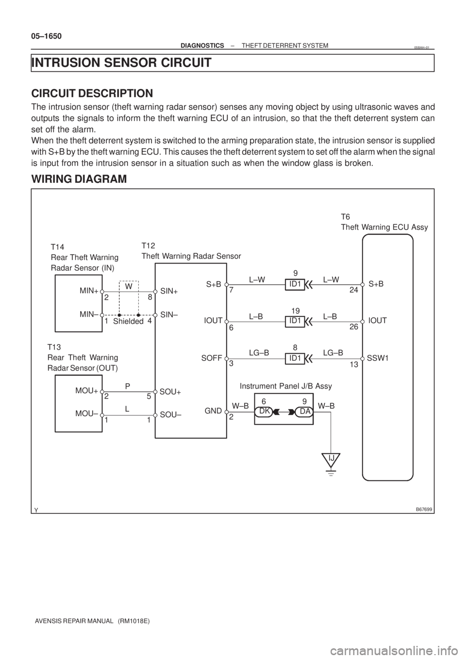
INTRUSION SENSOR CIRCUIT
CIRCUIT DESCRIPTION
The intrusion sensor (theft warning radar sensor) senses any moving object by using ultrasonic waves and
outputs the signals to inform the theft warning ECU of an intrusion, so that the theft deterrent system can
set off the alarm.
When the theft deterrent system is switched to the arming preparation state, the intrusion sensor is supplied
with S+B by the theft warning ECU. This causes the theft deterrent system to set off the alarm when the signal
is input from the intrusion sensor in a situation such as when the window glass is broken.
WIRING DIAGRAM
05BAH±01
Page 1729 of 5135
B67866
T12
Theft Warning Radar Sensor
1 2 4
87653
B69135
HIGH
(10 ± 14 V)
LOW
(0.2 ± 0.8 V)T1: 0.2 sec.
T2: 0.1 sec.
T1T2
± DIAGNOSTICSTHEFT DETERRENT SYSTEM
05±1651
AVENSIS REPAIR MANUAL (RM1018E)
INSPECTION PROCEDURE
1 CHECK THEFT WARNING RADAR SENSOR (OPERATION)
(a) Set the theft deterrent system with a window open and after 30 seconds insert your hand through the
window and shake it near the sensor to check if the alarm is triggered.
OK NO PROBLEM
NG
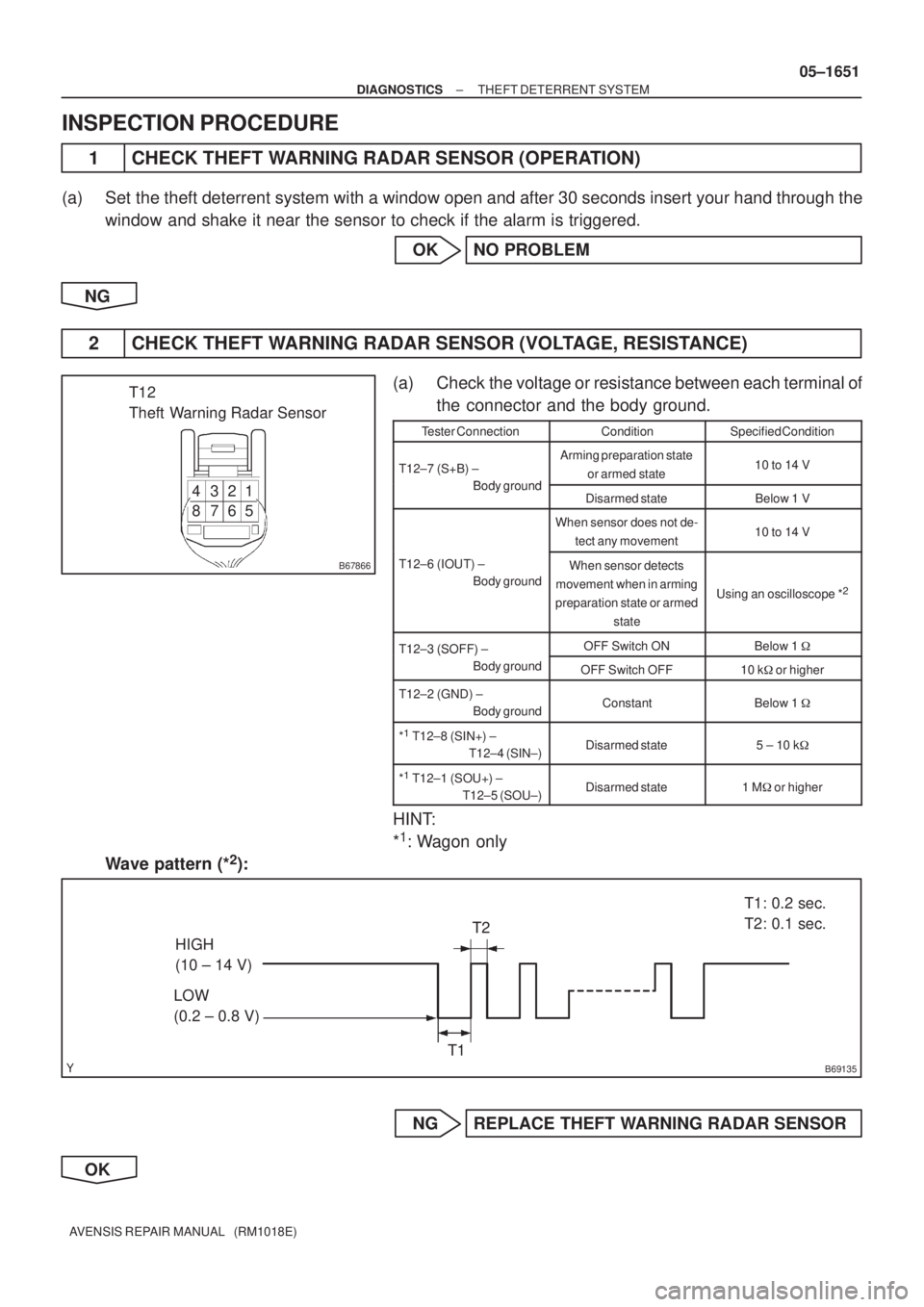
2 CHECK THEFT WARNING RADAR SENSOR (VOLTAGE, RESISTANCE)
(a) Check the voltage or resistance between each terminal of
the connector and the body ground.
Tester ConnectionConditionSpecified Condition
T12±7 (S+B) ±
Body ground
Arming preparation state
or armed state10 to 14 V
Body groundDisarmed stateBelow 1 V
When sensor does not de-
tect any movement10 to 14 V
T12±6 (IOUT) ±
Body groundWhen sensor detects
movement when in arming
preparation state or armed
state
Using an oscilloscope *2
T12±3 (SOFF) ± OFF Switch ONBelow 1 �T12 3 (SOFF)
Body ground
OFF Switch OFF10 k� or higher
T12±2 (GND) ±
Body groundConstantBelow 1 �
*1
T12±8 (SIN+) ±
T12±4 (SIN±)Disarmed state5 ± 10 k�
*1
T12±1 (SOU+) ±
T12±5 (SOU±)Disarmed state1 M� or higher
HINT:
*
1: Wagon only
Wave pattern (*
2):
NG REPLACE THEFT WARNING RADAR SENSOR
OK
Page 2974 of 5135
H40007
10 m (33 ft) or more
Battery
SST(s)
H40005
Battery
SST(s)
±
SUPPLEMENTAL RESTRAINT SYSTEM HORN BUTTON ASSY
60±21
AVENSIS REPAIR MANUAL (RM1018E)
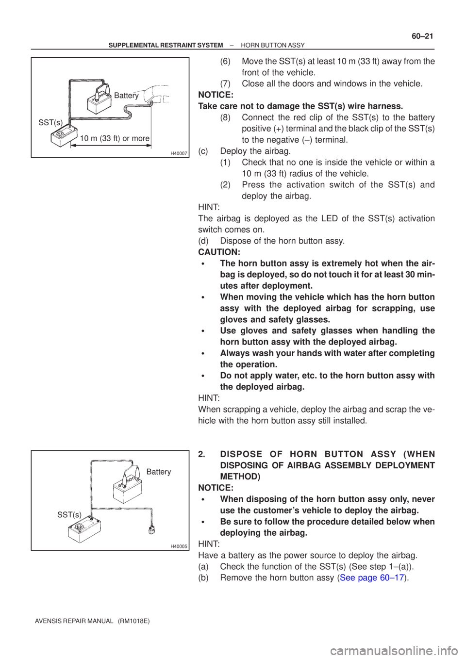
(6) Move the SST(s) at least 10 m (33 ft) away from the
front of the vehicle.
(7) Close all the doors and windows in the vehicle.
NOTICE:
Take care not to damage the SST(s) wire harness. (8) Connect the red clip of the SST(s) to the batterypositive (+) terminal and the black clip of the SST(s)
to the negative (±) terminal.
(c) Deploy the airbag. (1) Check that no one is inside the vehicle or within a10 m (33 ft) radius of the vehicle.
(2) Press the activation switch of the SST(s) and
deploy the airbag.
HINT:
The airbag is deployed as the LED of the SST(s) activation
switch comes on.
(d) Dispose of the horn button assy.
CAUTION:
�The horn button assy is extremely hot when the air-
bag is deployed, so do not touch it for at least 30 min-
utes after deployment.
�When moving the vehicle which has the horn button
assy with the deployed airbag for scrapping, use
gloves and safety glasses.
�Use gloves and safety glasses when handling the
horn button assy with the deployed airbag.
�Always wash your hands with water after completing
the operation.
�Do not apply water, etc. to the horn button assy with
the deployed airbag.
HINT:
When scrapping a vehicle, deploy the airbag and scrap the ve-
hicle with the horn button assy still installed.
2. DISPOSE OF HORN BUTTON ASSY (WHEN DISPOSING OF AIRBAG ASSEMBLY DEPLOYMENT
METHOD)
NOTICE:
�When disposing of the horn button assy only, never
use the customer's vehicle to deploy the airbag.
�Be sure to follow the procedure detailed below when
deploying the airbag.
HINT:
Have a battery as the power source to deploy the airbag.
(a) Check the function of the SST(s) (See step 1±(a)).
(b)Remove the horn button assy (See page 60±17).
Page 3019 of 5135
H42660
H42662
SST(s)
SST(s)
H41078
10 m (33 ft) or more
SST(s)Battery 60±56
± SUPPLEMENTAL RESTRAINT SYSTEMINSTRUMENT PANEL AIR BAG ASSY
AVENSIS REPAIR MANUAL (RM1018E)
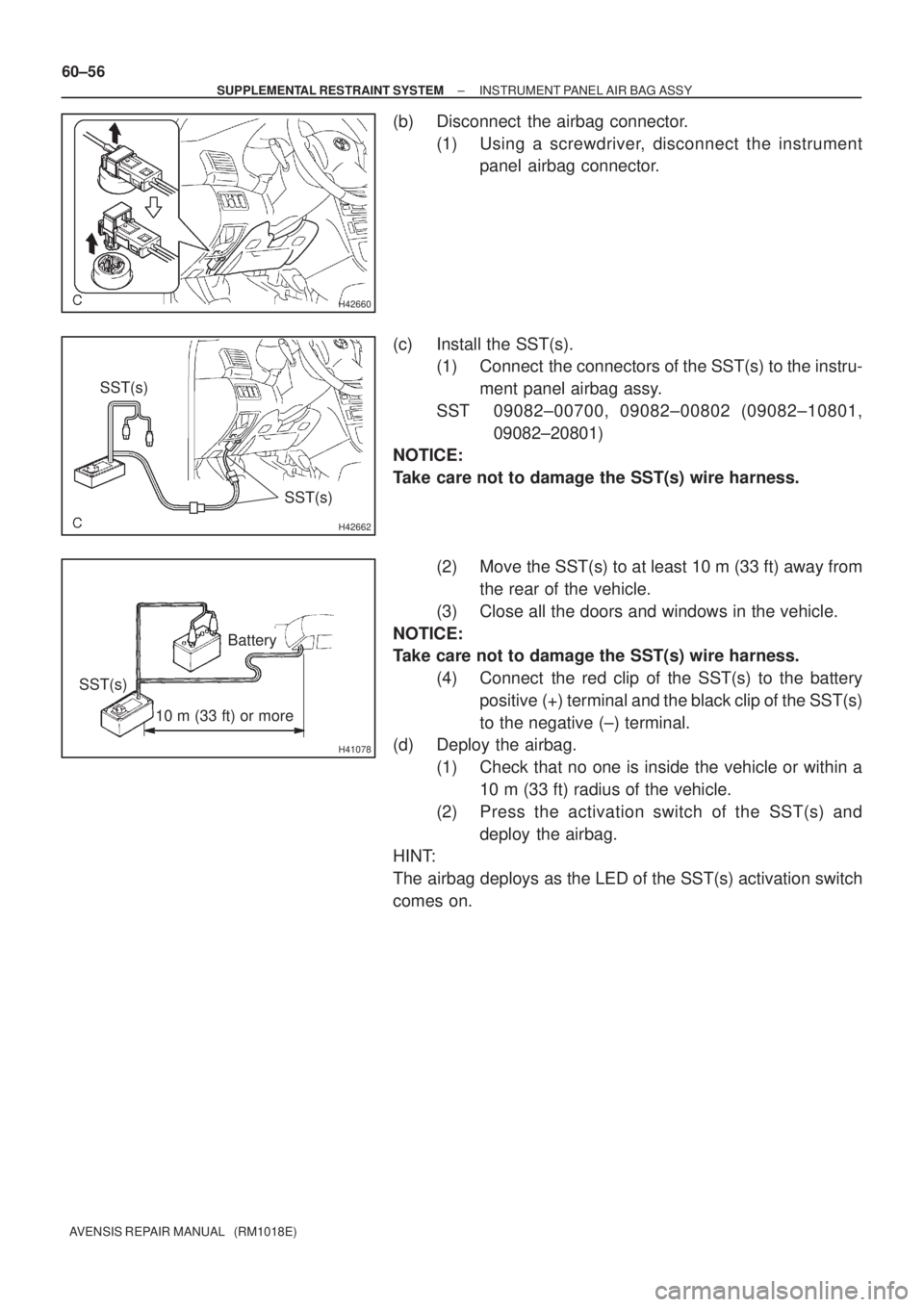
(b) Disconnect the airbag connector.
(1) Using a screwdriver, disconnect the instrument
panel airbag connector.
(c) Install the SST(s).
(1) Connect the connectors of the SST(s) to the instru-
ment panel airbag assy.
SST 09082±00700, 09082±00802 (09082±10801,
09082±20801)
NOTICE:
Take care not to damage the SST(s) wire harness.
(2) Move the SST(s) to at least 10 m (33 ft) away from
the rear of the vehicle.
(3) Close all the doors and windows in the vehicle.
NOTICE:
Take care not to damage the SST(s) wire harness.
(4) Connect the red clip of the SST(s) to the battery
positive (+) terminal and the black clip of the SST(s)
to the negative (±) terminal.
(d) Deploy the airbag.
(1) Check that no one is inside the vehicle or within a
10 m (33 ft) radius of the vehicle.
(2) Press the activation switch of the SST(s) and
deploy the airbag.
HINT:
The airbag deploys as the LED of the SST(s) activation switch
comes on.
Page 3027 of 5135
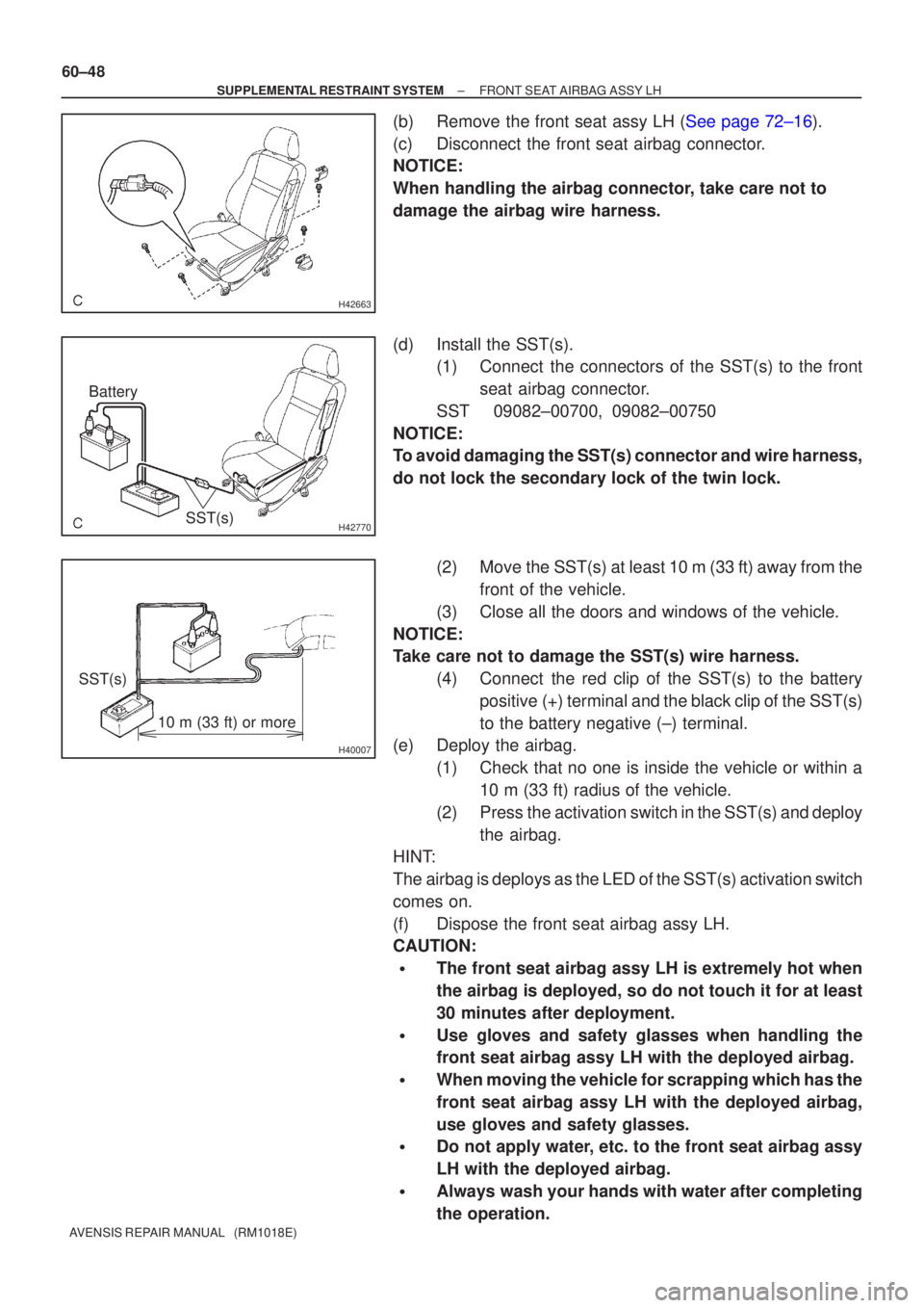
H42663
H42770
BatterySST(s)
H40007
10 m (33 ft) or more
SST(s)
60±48
±
SUPPLEMENTAL RESTRAINT SYSTEM FRONT SEAT AIRBAG ASSY LH
AVENSIS REPAIR MANUAL (RM1018E)
(b)Remove the front seat assy LH (See page 72±16).
(c) Disconnect the front seat airbag connector.
NOTICE:
When handling the airbag connector, take care not to
damage the airbag wire harness.
(d) Install the SST(s). (1) Connect the connectors of the SST(s) to the front
seat airbag connector.
SST 09082±00700, 09082±00750
NOTICE:
To avoid damaging the SST(s) connector and wire harness,
do not lock the secondary lock of the twin lock.
(2) Move the SST(s) at least 10 m (33 ft) away from thefront of the vehicle.
(3) Close all the doors and windows of the vehicle.
NOTICE:
Take care not to damage the SST(s) wire harness. (4) Connect the red clip of the SST(s) to the batterypositive (+) terminal and the black clip of the SST(s)
to the battery negative (±) terminal.
(e) Deploy the airbag.
(1) Check that no one is inside the vehicle or within a10 m (33 ft) radius of the vehicle.
(2) Press the activation switch in the SST(s) and deploy the airbag.
HINT:
The airbag is deploys as the LED of the SST(s) activation switch
comes on.
(f) Dispose the front seat airbag assy LH.
CAUTION:
�The front seat airbag assy LH is extremely hot when
the airbag is deployed, so do not touch it for at least
30 minutes after deployment.
�Use gloves and safety glasses when handling the
front seat airbag assy LH with the deployed airbag.
�When moving the vehicle for scrapping which has the
front seat airbag assy LH with the deployed airbag,
use gloves and safety glasses.
�Do not apply water, etc. to the front seat airbag assy
LH with the deployed airbag.
�Always wash your hands with water after completing
the operation.
Page 3033 of 5135
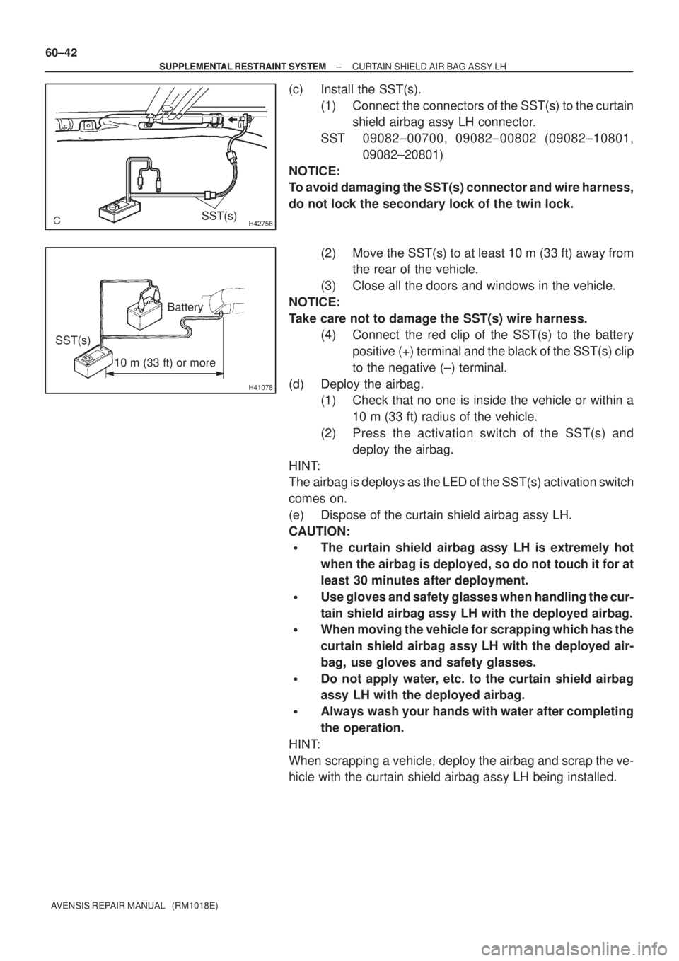
H42758SST(s)
H41078
10 m (33 ft) or more
SST(s)Battery 60±42
± SUPPLEMENTAL RESTRAINT SYSTEMCURTAIN SHIELD AIR BAG ASSY LH
AVENSIS REPAIR MANUAL (RM1018E)
(c) Install the SST(s).
(1) Connect the connectors of the SST(s) to the curtain
shield airbag assy LH connector.
SST 09082±00700, 09082±00802 (09082±10801,
09082±20801)
NOTICE:
To avoid damaging the SST(s) connector and wire harness,
do not lock the secondary lock of the twin lock.
(2) Move the SST(s) to at least 10 m (33 ft) away from
the rear of the vehicle.
(3) Close all the doors and windows in the vehicle.
NOTICE:
Take care not to damage the SST(s) wire harness.
(4) Connect the red clip of the SST(s) to the battery
positive (+) terminal and the black of the SST(s) clip
to the negative (±) terminal.
(d) Deploy the airbag.
(1) Check that no one is inside the vehicle or within a
10 m (33 ft) radius of the vehicle.
(2) Press the activation switch of the SST(s) and
deploy the airbag.
HINT:
The airbag is deploys as the LED of the SST(s) activation switch
comes on.
(e) Dispose of the curtain shield airbag assy LH.
CAUTION:
�The curtain shield airbag assy LH is extremely hot
when the airbag is deployed, so do not touch it for at
least 30 minutes after deployment.
�Use gloves and safety glasses when handling the cur-
tain shield airbag assy LH with the deployed airbag.
�When moving the vehicle for scrapping which has the
curtain shield airbag assy LH with the deployed air-
bag, use gloves and safety glasses.
�Do not apply water, etc. to the curtain shield airbag
assy LH with the deployed airbag.
�Always wash your hands with water after completing
the operation.
HINT:
When scrapping a vehicle, deploy the airbag and scrap the ve-
hicle with the curtain shield airbag assy LH being installed.
Page 3044 of 5135
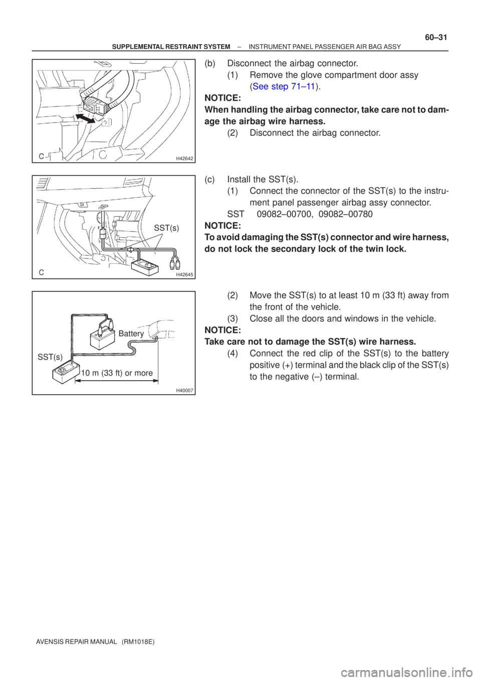
H42642
H42645
SST(s)
H40007
10 m (33 ft) or more
Battery
SST(s)
±
SUPPLEMENTAL RESTRAINT SYSTEM INSTRUMENT PANEL PASSENGER AIR BAG ASSY
60±31
AVENSIS REPAIR MANUAL (RM1018E)
(b) Disconnect the airbag connector.
(1) Remove the glove compartment door assy (See step 71±11).
NOTICE:
When handling the airbag connector, take care not to dam-
age the airbag wire harness. (2) Disconnect the airbag connector.
(c) Install the SST(s). (1) Connect the connector of the SST(s) to the instru-
ment panel passenger airbag assy connector.
SST 09082±00700, 09082±00780
NOTICE:
To avoid damaging the SST(s) connector and wire harness,
do not lock the secondary lock of the twin lock.
(2) Move the SST(s) to at least 10 m (33 ft) away fromthe front of the vehicle.
(3) Close all the doors and windows in the vehicle.
NOTICE:
Take care not to damage the SST(s) wire harness. (4) Connect the red clip of the SST(s) to the batterypositive (+) terminal and the black clip of the SST(s)
to the negative (±) terminal.