Page 1558 of 5135
B70496
Front Door w/ Motor
Lock Assy LH
Front Door Courtesy
Lamp Switch Assy
Rear Door w/ Motor
Lock Assy LH
Rear Door Courtesy
Lamp Switch AssyFront Door Courtesy
Lamp Switch Assy
Rear Door w/ Motor
Lock Assy RH
Rear Door Courtesy
Lamp Switch Assy Front Door w/ Motor
Lock Assy RH
Sedan Models
Wagon Models Liftback Models
Back Door Lock Assy Power Window Regulator Master Switch Assy
� Door Control SwitchBack Door Lock Assy
Back Door Opener Switch Assy
(Outside Handle Switch)
Back Door Lock Assy
Back Door Opener Switch Assy
(Outside Handle Switch)Back Door Opener Switch Assy
(Outside Handle Switch)
± DIAGNOSTICSPOWER DOOR LOCK CONTROL SYSTEM
05±1541
AVENSIS REPAIR MANUAL (RM1018E)
Page 1619 of 5135

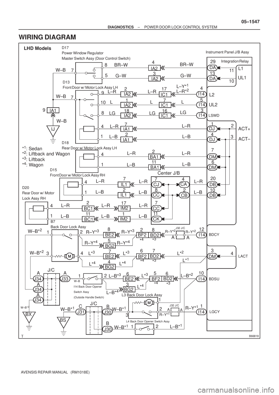
B66818
ACT+ L1
UL1
Integration Relay
DA
DA11
10 29
13
5 8
D17
Power Window Regulator
Master Switch Assy (Door Control Switch)
7
L2 9
10
18
4 7
D13
Front Door w/ Motor Lock Assy LH
UL2
LSWD
ACT±
20
10
D15
Front Door w/ Motor Lock Assy RH
B7
Back Door Lock AssyInstrument Panel J/B Assy
LHD Models
4
5
3
DJ1
DJ4
DM7
DM6
1 4
D18
Rear Door w/ Motor Lock Assy LH
DB
DB 1 4D20
Rear Door w/ Motor
Lock Assy RH
1 4
BDCYI1412
12
4
3
LACT4
DM3
1
2
3 2
12
L3 Back Door Lock Assy
I14 Back Door Opener
Switch Assy
(Outside Handle Switch)
L4 Back Door Opener Switch Assy
LGCY
1
1BDSU
10 W±BBR±W
IA2
IC1
IA1
BA1
CA
CJ
CC
CC
CK IL1
BC1IM2
BE2
BG2R±Y*
3BF2
BD2
J34A
W±B*2J/C
J31 IA1
IJG±W
IA2
IC1
IC1
IA1BR±W
G±W 4
3
17
7
16
7
2
2
11
BA1 L±R
L
L±R
L±B
Center J/B LG
L±R
L±B
L±R
L±B
L±R
L±B L±R
L±B L±R
L±B
BC1IL1
IM2
R±Y*
3
R±Y*4R±Y*4
8
5 2
117
172
1
W±B*2
W±B*2
BE2
5 4
BG27
L*
4
L*3
J34
J34
BX
BS
J30 W±B*
1C
B
B J30W±B*1
W±B*1
A
AA
J33 BE26*
4*3R±Y*
228
A
A
I14
I14
L±B*
1 A
A
J32 J/C
R±Y*1
R±Y*1
L*3BF2BD2
*4*3
7 6
L*2
L*1
BF2BD26
*4*3
CBL±R
L±B
L±R
L±B
8 7
7
112 4
L±R
L±B
L*
4
L±B*3L±B*2L*3
L±R*2L±Y*1
I14
I14
I14 L
LG
2
3
*
1: Sedan
*2: Liftback and Wagon
*3: Liftback
*4: Wagon9W±B
L±R
L±B
R±Y*2
J/C
BG23
L*
4
L±B*4
J32 J/C
L±R
L
LGIA2
IA22
1
18 IA2
W±B
W±B
± DIAGNOSTICSPOWER DOOR LOCK CONTROL SYSTEM
05±1547
AVENSIS REPAIR MANUAL (RM1018E)
WIRING DIAGRAM
Page 1620 of 5135

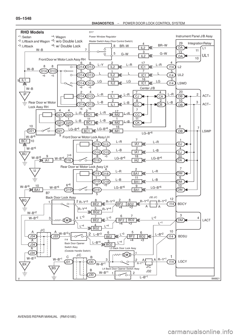
B66821
ACT+ L1
UL1
Integration Relay
DA
DA11
10 29
13
5 8
D17
Power Window Regulator
Master Switch Assy (Door Control Switch)
7
L2 8
7 Front Door w/ Motor Lock Assy RH
UL2
LSWD
ACT± 20
10
Front Door w/ Motor Lock Assy LH
B7
Back Door Lock AssyInstrument Panel J/B Assy
RHD Models
I144
5
3
DJ1
DJ4
DM7
DM6 34 Rear Door w/ Motor
Lock Assy RHDB
DB
Rear Door w/ Motor Lock Assy LH
BDCY I1412
12
4
3
LACT 4
DM3
1
2 3
2
12
L4 Back Door Opener Switch Assy
LGCY
1
1BDSU 10 6
5
76
5
14
1 2D13
D13
D13
D13
D13 D14 D14D14 D14 D14 8
D13 D14
34
D21
D21
D15
D15 D16 D16
1 4 14
D20
D20
D18
D1814
D19
D19 *
5*6
*5: w/o Double Lock
*6: w/ Double Lock
*5*6
*5*6
*5*6
*5
*5*6
IL2
IC1 IL2
IM2
LG±B*
6
IA1
BA1CJ
CC
CKCA
CB 16 BR±W
G±W
L±Y
L
LGIC1
IC1 IL2
7 174
3
G±W BR±W
IL2
IL22
1
18L±R
L
LGL±R
L
LG W±B
9IL1
W±BW±B
IP
L±R
L±BIL1
IL12 7
L±R
L±B
CC7
8
7
11
IM2
IM1 BC1
BC1
BC1 L±R
L±B
D21
9LG±B*
6
LG±B*6
17
1612 4
L±R
L±B
D21
W±B*
6
BC1 10
BU
IJ W±B*
6
W±B*6
IA19 10
D16Center J/B
2
7 3
DB8
LSWP
DA20 7*
6
D168L±R
L±B
LG±B*6
L±R
L±BI14
I14
7
2
18 IA1
IA2LG±B*
6
L±R
L±B
D1912
5L±R
L±B
LG±B*
6
2
11
9 BA1
BA1L±R
L±B
LG±B*
6DM10
D196*
6
W±B*6
W±B*610
BA1 W±B*6
BQ
BXBE2
BG2R±Y*3BF2
BD2
J34
J/C
J31R±Y*3
R±Y*4R±Y*4
8
5
W±B*
2BE2
4
BG27
L*
4
L*3
J30 W±B*
1C
B
B J30
W±B*
1
W±B*1
AJ33
BE26
*4*3R±Y*
228
A
A
L±B*
1
L*3BF2BD2
*4*37 6
L*
2
L*1
BF2
BD26
*4*3 L*
4
L±B*3L±B*2L*3I14
I14 W±B*
2
J/C
I14
Back Door Opener
Switch Assy
(Outside Handle Switch)
BS
L3 Back Door Lock Assy
R±Y
*1
W±B*2
AAA
J34
J345
AAR±Y*
1
*1: Sedan
*2: Liftback and Wagon
*3: Liftback*
4: Wagon
R±Y*
2J32 J/C
3
BG2 L±B*4L*4
W±B*2
L±R
L±B
911 2
J/C
J32
05±1548
± DIAGNOSTICSPOWER DOOR LOCK CONTROL SYSTEM
AVENSIS REPAIR MANUAL (RM1018E)
Page 1622 of 5135
B68460
LOCK
UNLOCK
Door Control Switch
123 6 745 8918 19 22 2320 21 24
10 11 14 15
12 13 16 17
05±1550
± DIAGNOSTICSPOWER DOOR LOCK CONTROL SYSTEM
AVENSIS REPAIR MANUAL (RM1018E)
4 INSPECT POWER WINDOW REGULATOR MASTER SWITCH ASSY
(a) Remove the master switch.
(b) Inspect the door control switch resistance.
Standard:
Tester ConnectionDoor Lock PositionSpecified Condition
7 ± 8LockBelow 1 �
7 ± 8, 5 ± 7OFF10 k�or higher
5 ± 7UnlockBelow 1 �
NG REPLACE POWER WINDOW REGULATOR
MASTER SWITCH ASSY
OK
Page 1623 of 5135
17
34
16
33
1532
14 31
13 30
1229
11 2 8
1027
926
825
724
623
522
4
21
320
2
19
118
B70497
DA
Instrument Panel J/B Assy Wire Harness Side
D17
Power Window Regulator
Master Switch Assy
± DIAGNOSTICSPOWER DOOR LOCK CONTROL SYSTEM
05±1551
AVENSIS REPAIR MANUAL (RM1018E)
5 CHECK WIRE HARNESS(POWER WINDOW REGULATOR MASTER SWITCH ASSY
± INSTRUMENT PANEL J/B ASSY (INTEGRATION RELAY) AND BODY GROUND)
(a) Disconnect the D17 switch and DA J/B connectors.
(b) Check the resistance between the wire harness side con-
nectors.
Standard (Check for open):
Tester ConnectionSpecified Condition
D17±8 ± DA±29 (L1)Below 1�D17±5 ± DA13±1 (UL1)Below 1 �
(c) Check the resistance between the D17 switch connector
and body ground.
Standard (Check for open):
Tester ConnectionSpecified Condition
D17±7 ± Body groundBelow 1 �
NG REPAIR OR REPLACE HARNESS AND
CONNECTOR
OK
REPLACE INSTRUMENT PANEL JUNCTION BLOCK ASSY
Page 1627 of 5135
05C8A±01
±
DIAGNOSTICS POWER DOOR LOCK CONTROL SYSTEM
05±1545
AVENSIS REPAIR MANUAL (RM1018E)
PROBLEM SYMPTOMS TABLE
SymptomSuspected AreaSee Page
All doors cannot be locked/unlocked at once
3. DOOR fuse
4. ECU±B 2 fuse
5. Power window regulator master switch assy
6. Front door lock assy LH, RH (Driver side)
7. Instrument panel J/B assy (Integration relay)
8. Wire harness
05±1546
Key lock±in prevention function does not work properly (Manual
operation and operation interlocked with key are active)
1. Unlock warning switch assy
2. Courtesy lamp switch assy LH, RH (Driver side)
3. Instrument panel J/B assy (Integration relay)
4. Wire harness
05±1555
w/ Double lock:
Double lock function does not operate properly
1. Wireless system
2. DOOR fuse
3. ECU±B 2 fuse
4. Front door lock assy LH, RH
5. Rear door lock assy LH, RH
6. Instrument panel J/B assy (Integration relay)
7. Wire harness
05±1560
Page 1665 of 5135

B67692
T6
Theft Warning ECU Assy
IND
25 W±B
1LSecurity A J16
J/C
18V F19
Rear Window Defogger
Switch Assy
(Security Indicator)
B67862
± DIAGNOSTICSTHEFT DETERRENT SYSTEM
05±1635
AVENSIS REPAIR MANUAL (RM1018E)
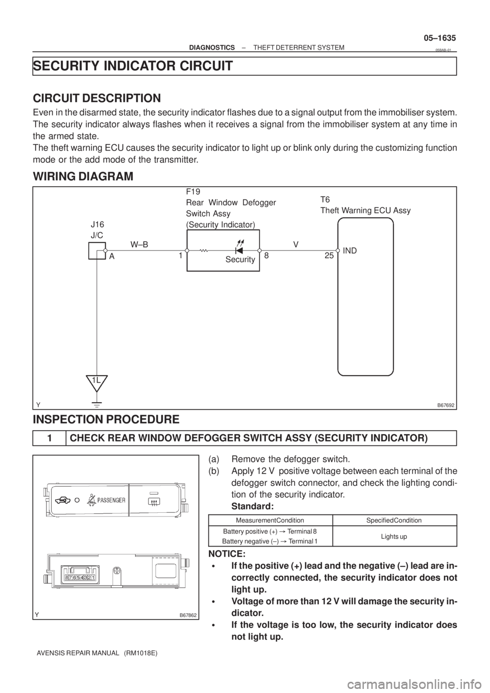
SECURITY INDICATOR CIRCUIT
CIRCUIT DESCRIPTION
Even in the disarmed state, the security indicator flashes due to a signal output from the immobiliser system.
The security indicator always flashes when it receives a signal from the immobiliser system at any time in
the armed state.
The theft warning ECU causes the security indicator to light up or blink only during the customizing function
mode or the add mode of the transmitter.
WIRING DIAGRAM
INSPECTION PROCEDURE
1 CHECK REAR WINDOW DEFOGGER SWITCH ASSY (SECURITY INDICATOR)
(a) Remove the defogger switch.
(b) Apply 12 V positive voltage between each terminal of the
defogger switch connector, and check the lighting condi-
tion of the security indicator.
Standard:
Measurement ConditionSpecified Condition
Battery positive (+) � Terminal 8
Battery negative (±) � Terminal 1Lights up
NOTICE:
�If the positive (+) lead and the negative (±) lead are in-
correctly connected, the security indicator does not
light up.
�Voltage of more than 12 V will damage the security in-
dicator.
�If the voltage is too low, the security indicator does
not light up.
05BAB±01
Page 1666 of 5135

������
������B68490
Wire Harness Side
T6
Theft Warning ECU Assy
F19
Rear Window Defogger Switch Assy
B67863
Wire Harness Side
F19
Rear Window Defogger Switch Assy
05±1636
± DIAGNOSTICSTHEFT DETERRENT SYSTEM
AVENSIS REPAIR MANUAL (RM1018E)
NG REPLACE REAR WINDOW DEFOGGER
SWITCH ASSY
OK
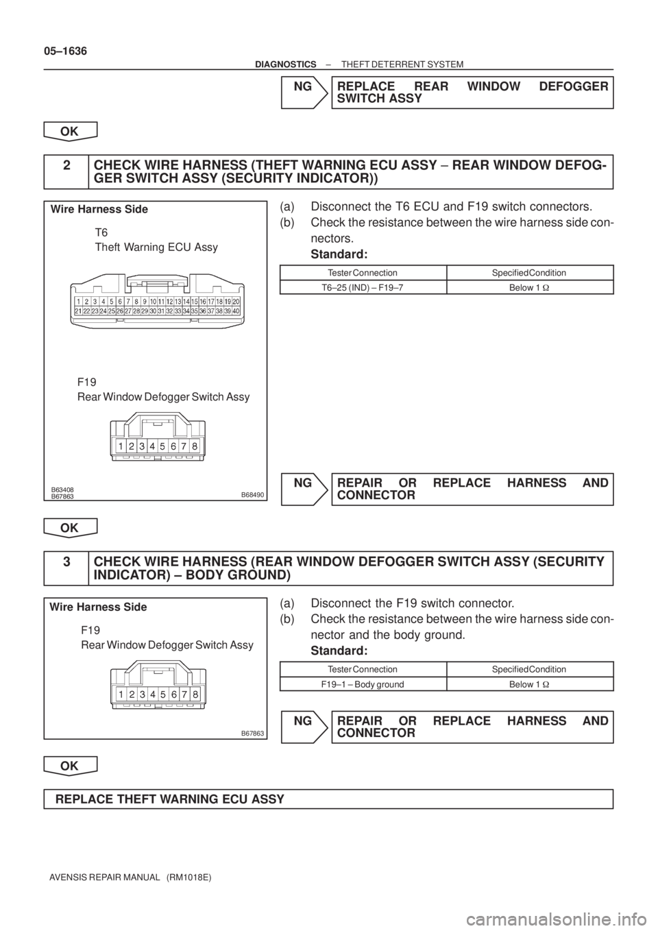
2 CHECK WIRE HARNESS (THEFT WARNING ECU ASSY ± REAR WINDOW DEFOG-
GER SWITCH ASSY (SECURITY INDICATOR))
(a) Disconnect the T6 ECU and F19 switch connectors.
(b) Check the resistance between the wire harness side con-
nectors.
Standard:
Tester ConnectionSpecified Condition
T6±25 (IND) ± F19±7Below 1 �
NG REPAIR OR REPLACE HARNESS AND
CONNECTOR
OK
3 CHECK WIRE HARNESS (REAR WINDOW DEFOGGER SWITCH ASSY (SECURITY
INDICATOR) ± BODY GROUND)
(a) Disconnect the F19 switch connector.
(b) Check the resistance between the wire harness side con-
nector and the body ground.
Standard:
Tester ConnectionSpecified Condition
F19±1 ± Body groundBelow 1 �
NG REPAIR OR REPLACE HARNESS AND
CONNECTOR
OK
REPLACE THEFT WARNING ECU ASSY