Page 482 of 5135

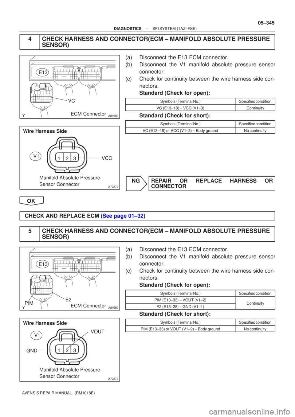
A81699
VC
E13ECM Connector
123
A72877
VCC
Manifold Absolute Pressure
Sensor Connector
Wire Harness SideV1
A81699PIM
E2
E13
ECM Connector
123
A72877
VOUT
GND Manifold Absolute Pressure
Sensor Connector
Wire Harness SideV1
±
DIAGNOSTICS SFI SYSTEM(1AZ±FSE)
05±345
AVENSIS REPAIR MANUAL (RM1018E)
4CHECK HARNESS AND CONNECTOR(ECM ± MANIFOLD ABSOLUTE PRESSURE
SENSOR)
(a)Disconnect the E13 ECM connector.
(b)Disconnect the V1 manifold absolute pressure sensor
connector.
(c)Check for continuity between the wire harness side con- nectors.
Standard (Check for open):
Symbols (Terminal No.)Specified condition
VC (E13±18) ± VCC (V1±3)Continuity
Standard (Check for short):
Symbols (Terminal No.)Specified condition
VC (E13±18) or VCC (V1±3) ± Body groundNo continuity
NGREPAIR OR REPLACE HARNESS OR CONNECTOR
OK
CHECK AND REPLACE ECM (See page 01±32)
5 CHECK HARNESS AND CONNECTOR(ECM ± MANIFOLD ABSOLUTE PRESSURE SENSOR)
(a) Disconnect the E13 ECM connector.
(b) Disconnect the V1 manifold absolute pressure sensor
connector.
(c) Check for continuity between the wire harness side con- nectors.
Standard (Check for open):
Symbols (Terminal No.)Specified condition
PIM (E13±33) ± VOUT (V1±2)ContinuityE2 (E13±28) ± GND (V1±1)Continuity
Standard (Check for short):
Symbols (Terminal No.)Specified condition
PIM (E13±33) or VOUT (V1±2) ± Body groundNo continuity
Page 483 of 5135
05±346
± DIAGNOSTICSSFI SYSTEM (1AZ±FSE)
AVENSIS REPAIR MANUAL (RM1018E)
NG REPAIR OR REPLACE HARNESS OR
CONNECTOR
OK
REPLACE MANIFOLD ABSOLUTE PRESSURE SENSOR
Page 529 of 5135

05±394
± DIAGNOSTICSSFI SYSTEM (1AZ±FSE)
AVENSIS REPAIR MANUAL (RM1018E)
DTC P0171 SYSTEM TOO LEAN (BANK 1)
DTC P0172 SYSTEM TOO RICH (BANK 1)
DTC P0174 SYSTEM TOO LEAN (BANK 2)
DTC P0175 SYSTEM TOO RICH (BANK 2)
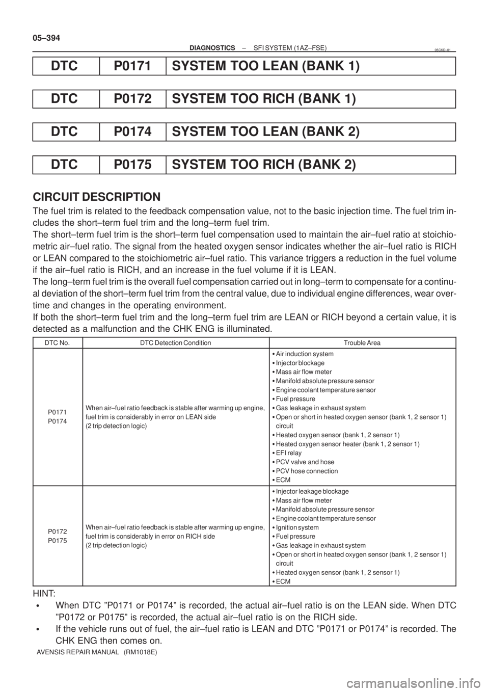
CIRCUIT DESCRIPTION
The fuel trim is related to the feedback compensation value, not to the basic injection time. The fuel trim in-
cludes the short±term fuel trim and the long±term fuel trim.
The short±term fuel trim is the short±term fuel compensation used to maintain the air±fuel ratio at stoichio-
metric air±fuel ratio. The signal from the heated oxygen sensor indicates whether the air±fuel ratio is RICH
or LEAN compared to the stoichiometric air±fuel ratio. This variance triggers a reduction in the fuel volume
if the air±fuel ratio is RICH, and an increase in the fuel volume if it is LEAN.
The long±term fuel trim is the overall fuel compensation carried out in long±term to compensate for a continu-
al deviation of the short±term fuel trim from the central value, due to individual engine differences, wear over-
time and changes in the operating environment.
If both the short±term fuel trim and the long±term fuel trim are LEAN or RICH beyond a certain value, it is
detected as a malfunction and the CHK ENG is illuminated.
DTC No.DTC Detection ConditionTrouble Area
P0171
P0174When air±fuel ratio feedback is stable after warming up engine,
fuel trim is considerably in error on LEAN side
(2 trip detection logic)
�Air induction system
�Injector blockage
�Mass air flow meter
�Manifold absolute pressure sensor
�Engine coolant temperature sensor
�Fuel pressure
�Gas leakage in exhaust system
�Open or short in heated oxygen sensor (bank 1, 2 sensor 1)
circuit
�Heated oxygen sensor (bank 1, 2 sensor 1)
�Heated oxygen sensor heater (bank 1, 2 sensor 1)
�EFI relay
�PCV valve and hose
�PCV hose connection
�ECM
P0172
P0175When air±fuel ratio feedback is stable after warming up engine,
fuel trim is considerably in error on RICH side
(2 trip detection logic)
�Injector leakage blockage
�Mass air flow meter
�Manifold absolute pressure sensor
�Engine coolant temperature sensor
�Ignition system
�Fuel pressure
�Gas leakage in exhaust system
�Open or short in heated oxygen sensor (bank 1, 2 sensor 1)
circuit
�Heated oxygen sensor (bank 1, 2 sensor 1)
�ECM
HINT:
�When DTC ºP0171 or P0174º is recorded, the actual air±fuel ratio is on the LEAN side. When DTC
ºP0172 or P0175º is recorded, the actual air±fuel ratio is on the RICH side.
�If the vehicle runs out of fuel, the air±fuel ratio is LEAN and DTC ºP0171 or P0174º is recorded. The
CHK ENG then comes on.
05CKD±01
Page 560 of 5135

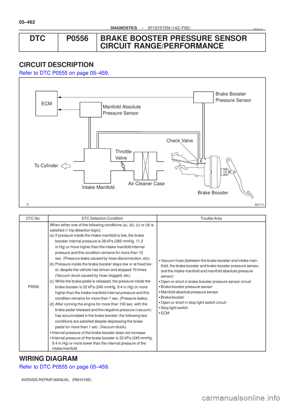
A81711
ECMManifold Absolute
Pressure Sensor
Brake Booster
Air Cleaner Case
Throttle
Valve
To Cylinder
Intake Manifold Check ValveBrake Booster
Pressure Sensor
05±462
±
DIAGNOSTICS SFI SYSTEM(1AZ±FSE)
AVENSIS REPAIR MANUAL (RM1018E)
DTCP0556BRAKE BOOSTER PRESSURE SENSOR CIRCUIT RANGE/PERFORMANCE
CIRCUIT DESCRIPTION
Refer to DTC P0555 on page 05±459.
DTC No.DTC Detection ConditionTrouble Area
P0556
When either one of the following conditions (a), (b), (c) or (d)\
is
satisfied (1 trip detection logic):
(a) If pressure inside the intake manifold is low, the brake
booster internal pressure is 38 kPa (285 mmHg, 11.2
in.Hg) or more higher than the intake manifold internal
pressure and this condition remains for more than 10
sec. (Pressure leaks caused by hose disconnection, etc).
(b) Pressure inside the brake booster stays low or at fixed lev- el, despite the vehicle has driven and stopped 10 times
(Vacuum stuck caused by hose clogged, etc).
(c) While the brake pedal is released, the pressure inside the brake booster is 32 kPa (240 mmHg, 9.4 in.Hg) or more
higher than the intake manifold internal pressure and this
condition remains for more than 1 sec. (Pressure leaks).
(d) After running the engine for more than 100 sec. with the brake pedal released and the negative pressure (vacuum)
has accumulated in the brake booster, the following two
conditions are satisfied despite depressing the brake
pedal for more than 1 sec. (Vacuum stuck):
� Internal pressure of the brake booster does not increase
� Internal pressure of the brake booster is 32 kPa (240 mmHg,
9.4 in.Hg) or more lower than the internal pressure of the
intake manifold
�Vacuum hose (between the brake booster and intake man-
ifold, the brake booster and brake booster pressure sensor,
and the intake manifold and manifold absolute pressure
sensor)
� Open or short in brake booster pressure sensor circuit
� Brake booster pressure sensor
� Manifold absolute pressure sensor
� Brake booster
� Open or short in stop light switch circuit
� Stop light switch
� ECM
WIRING DIAGRAM
Refer to DTC P0555 on page 05±459.
05CKO±01
Page 561 of 5135

±
DIAGNOSTICS SFI SYSTEM(1AZ±FSE)
05±463
AVENSIS REPAIR MANUAL (RM1018E)
INSPECTION PROCEDURE
HINT:
Read freeze frame data using
\b�\b�
��\b� �
�\f
����reeze frame data records the engine conditions when
a malfunction is detected. When troubleshooting, it is useful for determi\
ning whether the vehicle was running
or stopped, the engine was warmed up or not, the air±fuel ratio was lea\
n or rich, etc. at the time of the mal-
function.
1CHECK OTHER DTC OUTPUT(IN ADDITION TO P0556)
(a)Read the DTC using the hand±held tester. Result :
DisplayProceed to
Only ºP0556º is output.A
ºP0556º and other DTCs are output.B
HINT:
If any other codes besides ºP0556º are output, perform the troublesh\
ooting for those DTCs first.
BGO TO RELEVANT DTC CHART(See page 05±309)
A
2 READ VALUE OF HAND±HELD TESTER(INTAKE MANIFOLD ABSOLUTE PRESSURE)
(a) Connect the hand±held tester to the DLC3.
(b) Warm up the engine.
(c) Push the hand±held tester main switch ON.
(d) Select the item ºDIAGNOSIS / OBD/MOBD / DATA LIST / ALL / MAPº and read its value displayed on
the hand±held tester with the shift lever is the ºNº position.
Standard :
ConditionIntake Manifold Absolute Pressure
Ignition switch ON (do not start engine)70 to 110 kPa (525 to 825 mmHg, 20.7 to 32.5 in.Hg)
Running without load (2,500 rpm)20 to 35 kPa (150 to 263 mmHg, 5.9 to 10.4 in.Hg)
NG Go to step 7
OK
3 READ VALUE OF HAND±HELD TESTER(STOP LIGHT SWITCH)
(a) Connect the hand±held tester to the DLC3.
(b) Turn the ignition switch ON and push the hand±held tester main switch \
ON.
(c) Select the item ºDIAGNOSIS / OBD/MOBD / DATA LIST / ALL / STOP LIGHT SWº and read its value displayed on the hand±held tester.
Result :
Brake PedalSTP Signal
DepressedON
ReleasedOFF
Page 563 of 5135

A81699PBE2
E13
ECM Connector
VC
123
A72877
PIM
E2
Brake Booster Pressure
Sensor Connector Wire Harness SideB2
VC
± DIAGNOSTICSSFI SYSTEM (1AZ±FSE)
05±465
AVENSIS REPAIR MANUAL (RM1018E)
6 CHECK HARNESS AND CONNECTOR(ECM ± BRAKE BOOSTER PRESSURE
SENSOR)
(a) Disconnect the E13 ECM connector.
(b) Disconnect the B2 brake booster pressure sensor con-
nector.
(c) Check for continuity between the wire harness side con-
nectors.
Standard (Check for open):
Symbols (Terminal No.)Specified condition
VC (E13±18) ± VC (B2±3)
PB (E13±26) ± PIM (B2±2)Continuity
E2 (E13±28) ± E2 (B2±1)
y
Standard (Check for short):
Symbols (Terminal No.)Specified condition
VC (E13±18) or VC (B2±3) ± Body groundNo continuityPB (E13±26) or PIM (B2±2) ± Body groundNo continuity
NG REPAIR OR REPLACE HARNESS OR
CONNECTOR
OK
REPLACE BRAKE BOOSTER PRESSURE SENSOR
7 CHECK VACUUM HOSE(MANIFOLD ABSOLUTE PRESSURE SENSOR ± INTAKE
MANIFOLD)
(a) Check that the vacuum hose is connected correctly.
(b) Check that the vacuum hose is not loose or disconnected.
(c) Check the vacuum hose for clogs, cracks, holes, damage, or blockage.
NG REPAIR OR REPLACE VACUUM HOSE
OK
Page 564 of 5135
A81699PIME2
E13
ECM Connector
VC
123
A72877
VOUT
GND
Manifold Absolute Pressure
Sensor Connector Wire Harness SideV1
VCC
05±466
± DIAGNOSTICSSFI SYSTEM (1AZ±FSE)
AVENSIS REPAIR MANUAL (RM1018E)
8 CHECK HARNESS AND CONNECTOR(ECM ± MANIFOLD ABSOLUTE PRESSURE
SENSOR)
(a) Disconnect the E13 ECM connector.
(b) Disconnect the V1 manifold absolute pressure sensor
connector.
(c) Check for continuity between the wire harness side con-
nectors.
Standard (Check for open):
Symbols (Terminal No.)Specified condition
VC (E13±18) ± VCC (V1±3)
PIM (E13±33) ± VOUT (V1±2)Continuity
E2 (E13±28) ± GND (V1±1)
y
Standard (Check for short):
Symbols (Terminal No.)Specified condition
VC (E13±18) or VCC (V1±3) ± Body groundNo continuityPIM (E13±33) or VOUT (V1±2) ± Body groundNo continuity
NG REPAIR OR REPLACE HARNESS OR
CONNECTOR
OK
REPLACE MANIFOLD ABSOLUTE PRESSURE SENSOR
Page 624 of 5135
054JE±04
A80993
Mass Air Flow
Meter
DLC3
Accelerator Pedal Assy
(Accel Position Sensor) Injector
Diesel Turbo Inlet
Air Temperature Sensor
EGR Valve Assy
Engine Room R/B
No.3
Suction Control
Valve
Fuel Temperature
Sensor Common Rail Assy
(Fuel Pressure
Sensor Assy)Glow Plug Assy Camshaft Position
Sensor
Manifold Absolute
Pressure Sensor
EDU
ECM
Common Rail Assy
(Pressure Discharge Valve Assy)
Supply
Pump
Engine Room J/B
Engine Coolant Temperature Sensor
VRV
Crankshaft Position Sensor
Intake Shutter Assy
05±548
± DIAGNOSTICSECD SYSTEM (1CD±FTV)
AVENSIS REPAIR MANUAL (RM1018E)
LOCATION