Page 2177 of 5135
A77321
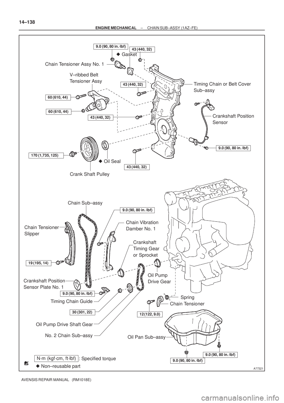
N´m (kgf´cm, ft´lbf)
: Specified torque
� Non±reusable part
43 (440, 32)
� Gasket
Chain Tensioner Assy No. 1
Timing Chain or Belt Cover
Sub±assy
Crankshaft Position
Sensor
9.0 (90, 80 in.�lbf)
V±ribbed Belt
Tensioner Assy
60 (610, 44)
60 (610, 44)
43 (440, 32)
43 (440, 32)
170 (1,735, 125)
Crank Shaft Pulley
� Oil Seal
43 (440, 32)
Chain Sub±assy
Chain Tensioner
Slipper
Chain Vibration
Damber No. 1
Crankshaft
Timing Gear
or Sprocket
19 (195, 14)
Crankshaft Position
Sensor Plate No. 1
Timing Chain Guide
Oil Pump
Drive Gear
12 (122, 9.0)
Spring
Chain Tensioner
Oil Pump Drive Shaft Gear
Oil Pan Sub±assy
9.0 (90, 80 in.�lbf)
9.0 (90, 80 in.�lbf)
9.0 (90, 80 in.�lbf)
30 (301, 22)
No. 2 Chain Sub±assy
9.0 (90, 80 in.�lbf)
9.0 (90, 80 in.�lbf)
14±138
± ENGINE MECHANICALCHAIN SUB±ASSY (1AZ±FE)
AVENSIS REPAIR MANUAL (RM1018E)
Page 2181 of 5135

AVENSIS REPAIR MANUAL (RM1018E)
REPLACEMENT
1.DISCHARGE FUEL SYSTEM PRESSURE (See page 11±30)
2.REMOVE FRONT WHEEL RH")
141BD±01
A77339
A77292
14±222
±
ENGINE MECHANICAL CHAIN SUB±ASSY(1AZ±FSE)
AVENSIS REPAIR MANUAL (RM1018E)
REPLACEMENT
1.DISCHARGE FUEL SYSTEM PRESSURE (See page 11±30)
2.REMOVE FRONT WHEEL RH
3.REMOVE RADIATOR SUPPORT OPENING COVER
4.REMOVE ENGINE ROOM COVER SIDE
5.REMOVE ENGINE UNDER COVER RH
6.REMOVE ENGINE UNDER COVER LH
7.DRAIN ENGINE OIL
(a)Install a new gasket and the drain plug after draining engine oil. Torque: 25 N �m (255 kgf �cm,18 ft �lbf)
8.REMOVE ENGINE COVER SUB±ASSY NO.1
(a)Remove the 2 nuts and the engine cover No. 1.
9.REMOVE FUEL PRESSURE PULSATION DAMPER ASSY
10.DISCONNECT FUEL TUBE SUB±ASSY (See page 11±33)
11.SEPARATE FUEL PIPE SUB±ASSY NO.1 (See page 11±52) SST 09023±12900
12.REMOVE FUEL PUMP ASSY (See page 11±52)
13.REMOVE FAN AND GENERATOR V BELT (See page 14±185) SST 09249±63010
14.REMOVE GENERATOR ASSY (See page 19±20)
15.REMOVE EXHAUST PIPE ASSY FRONT (See page 15±7)
16. SEPARATE VANE PUMP ASSY
(a) Remove the 2 through bolts and separate the vane pump.
Page 2182 of 5135
A77299
A77303
A77308
A77306
± ENGINE MECHANICALCHAIN SUB±ASSY (1AZ±FSE)
14±223
AVENSIS REPAIR MANUAL (RM1018E)
17. SEPARATE RETURN TUBE SUB±ASSY
(a) Remove the 3 bolts and separate the return tube as
shown in the illustration.
18. SEPARATE COOLER REFRIGERANT SUCTION HOSE
NO.1 (LHD STEERING POSITION TYPE)
(a) Remove the 2 nuts and separate the Cooler refrigerant
Suction hose No. 1.
19. SEPARATE VANE PUMP OIL RESERVOIR ASSY
20. REMOVE OIL RESERVOIR BRACKET NO.1
(a) Remove the 2 bolts and the oil pump reservoir bracket No.
1.
21. SEPARATE ENGINE WIRE
(a) Remove the bolt and separate the clamp and engine wire.
Page 2183 of 5135

AVENSIS REPAIR MANUAL (RM1018E)
22. REMOVE COOLER BRACKET (LHD STEERING
POSITION TYPE)")
A77307
A77346
A77284
A77345
Timing
Marks
Timing
Marks 14±224
± ENGINE MECHANICALCHAIN SUB±ASSY (1AZ±FSE)
AVENSIS REPAIR MANUAL (RM1018E)
22. REMOVE COOLER BRACKET (LHD STEERING
POSITION TYPE)
(a) Remove the bolt and cooler bracket.
23. REMOVE ENGINE SERVICE COVER BRACKET RH (RHD STEERING POSITION TYPE)
(a) Remove the bolt and the engine service cover bracket RH.
24. REMOVE IGNITION COIL ASSY
(a) Remove the 4 bolts and 4 ignition coils.
25. REMOVE CYLINDER HEAD COVER SUB±ASSY
(a) Disconnect the 2 PCV hoses from the cylinder head cov-
er.
(b) Remove the 9 bolts and 2 nuts, then remove the cylinder
head cover and gasket.
26. SET NO. 1 CYLINDER TO TDC/COMPRESSION
(a) Turn the crankshaft pulley, and align its groove with timing
mark 0 of the timing chain cover.
(b) Check that each timing mark of the camshaft timing gears
is aligned with the timing marks of the No. 1 and No. 2
bearing caps as shown in the illustration.
If not, turn the crankshaft 1 revolution (360�) and align the
marks as above.
Page 2185 of 5135
A77286
Push
A64641
A00019
A77288
14±226
±
ENGINE MECHANICAL CHAIN SUB±ASSY(1AZ±FSE)
AVENSIS REPAIR MANUAL (RM1018E)
30.REMOVE CHAIN TENSIONER ASSY NO.1
(a)Remove the 2 nuts, the chain tensioner No. 1 and gasket.
NOTICE:
Do not turn the crankshaft.
31.REMOVE CRANKSHAFT POSITION SENSOR (See page 18±17) 32. REMOVE OIL PAN SUB±ASSY
(a) Remove the 12 bolts and 2 nuts.
(b) Insert the blade of SST between the crank case, timingchain cover and oil pan, cut off applied sealer and remove
the oil pan.
SST 09032±00100
NOTICE:
Be careful not to damage the contact surface of the timing
chain cover, crank case and oil pan.
33. REMOVE V±RIBBED BELT TENSIONER ASSY
(a) Remove the bolt and nut, and then remove the V±ribbed belt tensioner.
Page 2187 of 5135
A77382
Groove90�
A77383
Groove
A66833
B11424
14±228
± ENGINE MECHANICALCHAIN SUB±ASSY (1AZ±FSE)
AVENSIS REPAIR MANUAL (RM1018E)
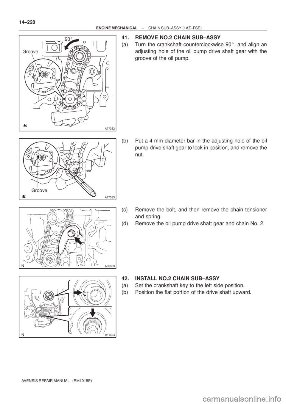
41. REMOVE NO.2 CHAIN SUB±ASSY
(a) Turn the crankshaft counterclockwise 90�, and align an
adjusting hole of the oil pump drive shaft gear with the
groove of the oil pump.
(b) Put a 4 mm diameter bar in the adjusting hole of the oil
pump drive shaft gear to lock in position, and remove the
nut.
(c) Remove the bolt, and then remove the chain tensioner
and spring.
(d) Remove the oil pump drive shaft gear and chain No. 2.
42. INSTALL NO.2 CHAIN SUB±ASSY
(a) Set the crankshaft key to the left side position.
(b) Position the flat portion of the drive shaft upward.
Page 2188 of 5135
A77384
Mark Link
Timing Mark
Timing Mark
Mark Link
A77385
Groove
A77386
Groove
A77387
90�
± ENGINE MECHANICALCHAIN SUB±ASSY (1AZ±FSE)
14±229
AVENSIS REPAIR MANUAL (RM1018E)
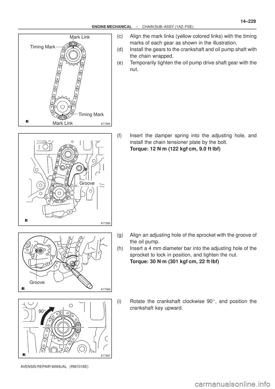
(c) Align the mark links (yellow colored links) with the timing
marks of each gear as shown in the illustration.
(d) Install the gears to the crankshaft and oil pump shaft with
the chain wrapped.
(e) Temporarily tighten the oil pump drive shaft gear with the
nut.
(f) Insert the damper spring into the adjusting hole, and
install the chain tensioner plate by the bolt.
Torque: 12 N�m (122 kgf�cm, 9.0 ft�lbf)
(g) Align an adjusting hole of the sprocket with the groove of
the oil pump.
(h) Insert a 4 mm diameter bar into the adjusting hole of the
sprocket to lock in position, and tighten the nut.
Torque: 30 N�m (301 kgf�cm, 22 ft�lbf)
(i) Rotate the crankshaft clockwise 90�, and position the
crankshaft key upward.
Page 2190 of 5135

14±231
AVENSIS REPAIR MANUAL (RM1018E)
47. INSTALL TIMING CHAIN GUIDE
Torque: 9.0 N�m (92 kgf�cm, 80 in.")
A77290
Hold
Stopper
A32629
A77390Seal Packing
± ENGINE MECHANICALCHAIN SUB±ASSY (1AZ±FSE)
14±231
AVENSIS REPAIR MANUAL (RM1018E)
47. INSTALL TIMING CHAIN GUIDE
Torque: 9.0 N�m (92 kgf�cm, 80 in.�lbf)
48. INSTALL CHAIN TENSIONER SLIPPER
(a) Install the chain tensioner slipper with bolt.
Torque: 19 N�m (195 kgf�cm, 14 ft�lbf)
(b) Check that the chain tensioner slipper is held on the cylin-
der block stopper.
49. INSTALL CRANKSHAFT POSITION SENSOR PLATE
NO.1
(a) Install the plate with the ºFº mark facing forward.
50. INSTALL TIMING CHAIN OR BELT COVER SUB±ASSY
NOTICE:
�Remove any oil from the contact surface.
�Install the chain cover within 3 minutes after applying
seal packing.
�Do not start the engine within 2 hours after installing.
(a) Remove any old packing (FIPG) material and be careful
not to drop any oil on the contact surfaces of the timing
chain cover.
(b) Apply a continuous bead (Diameter 2 mm (0.09 in.)) of
seal packing as shown in the illustration.
Seal packing: Part No. 08826 ± 00080 or equivalent.

14±223
AVENSIS REPAIR MANUAL (RM1018E)
17. SEPARATE RETURN TUBE SUB±ASSY
(a) Remove the 3 bolts and separate the return t")

AVENSIS REPAIR MANUAL (RM1018E)
30.REMOVE CHAIN TENSIONER ASSY NO.1
(a)Remove the 2 nuts, the chain tensioner")