Page 2226 of 5135

AVENSIS REPAIR MANUAL (RM1018E)
VALVE CLEARANCE(1AZ±FSE)
ADJUSTMENT
1.DISCHARGE")
141BL±01
A77339
A77343
No. 1 Cylinder TDC / CompressionIN
EX
14±186
±
ENGINE MECHANICAL VALVE CLEARANCE(1AZ±FSE)
AVENSIS REPAIR MANUAL (RM1018E)
VALVE CLEARANCE(1AZ±FSE)
ADJUSTMENT
1.DISCHARGE FUEL SYSTEM PRESSURE (See page 11±33)
2.REMOVE RADIATOR SUPPORT OPENING COVER
3.REMOVE ENGINE ROOM COVER SIDE
4.REMOVE ENGINE UNDER COVER RH 5.REMOVE ENGINE COVER SUB±ASSY NO.1
(a)Remove the 2 nuts and the engine cover No. 1.
6.REMOVE FUEL PRESSURE PULSATION DAMPER ASSY
7.REMOVE FUEL TUBE SUB±ASSY (See page 11±33)
8.REMOVE FUEL PIPE SUB±ASSY NO.1 (See page 11±52) SST 09023±12900
9. REMOVE IGNITION COIL ASSY
(a) Remove the 4 bolts and the ignition coils.
10.REMOVE CYLINDER HEAD COVER SUB±ASSY (See page 14±240)
11.SET NO. 1 CYLINDER TO TDC/COMPRESSION (See page 14±240)
12. INSPECT VALVE CLEARANCE
HINT:
Inspect and adjust the valve clearance when the engine is cold.
(a) Check only the valve indicated in the illustration.(1) Using a feeler gauge, measure the clearance be-tween the valve lifter and the camshaft.
(2) Record the out±of specification valve clearance measurements. They will be used later to determine
the required replacement adjusting shim.
Valve clearance (Cold):
Intake 0.19 to 0.29 mm (0.0075 to 0.0114 in.)
Exhaust 0.30 to 0.40 mm (0.0118 to 0.0157 in.)
(b) Turn the crankshaft clockwise 1 revolution (360 �) and set
No. 4 cylinder to TDC/compression.
Page 2231 of 5135
±
ENGINE MECHANICAL VALVE CLEARANCE(1AZ±FSE)
14±191
AVENSIS REPAIR MANUAL (RM1018E)
(h)Install the camshafts. (See page 14±240)
(i)Install the chain tensioner. (See page 14±240)
14.INSTALL CYLINDER HEAD COVER SUB±ASSY (See page 14±240)
15.INSTALL IGNITION COIL ASSY
Torque: 9.0 N �m (92 kgf �cm,80 in. �lbf)
16.INSTALL FUEL PIPE SUB±ASSY NO.1 (See page 11±52) SST09023±12900
17.INSTALL FUEL TUBE SUB±ASSY (See page 11±33)
18.INSTALL FUEL PRESSURE PULSATION DAMPER ASSY (See page 11±52)
19.CHECK FOR ENGINE OIL LEAKS
20.CHECK FOR FUEL LEAKS (
See page 11±33)
21. INSTALL ENGINE COVER SUB±ASSY NO.1 Torque: 7.0 N �m (71 kgf �cm, 62 in. �lbf)
Page 2238 of 5135
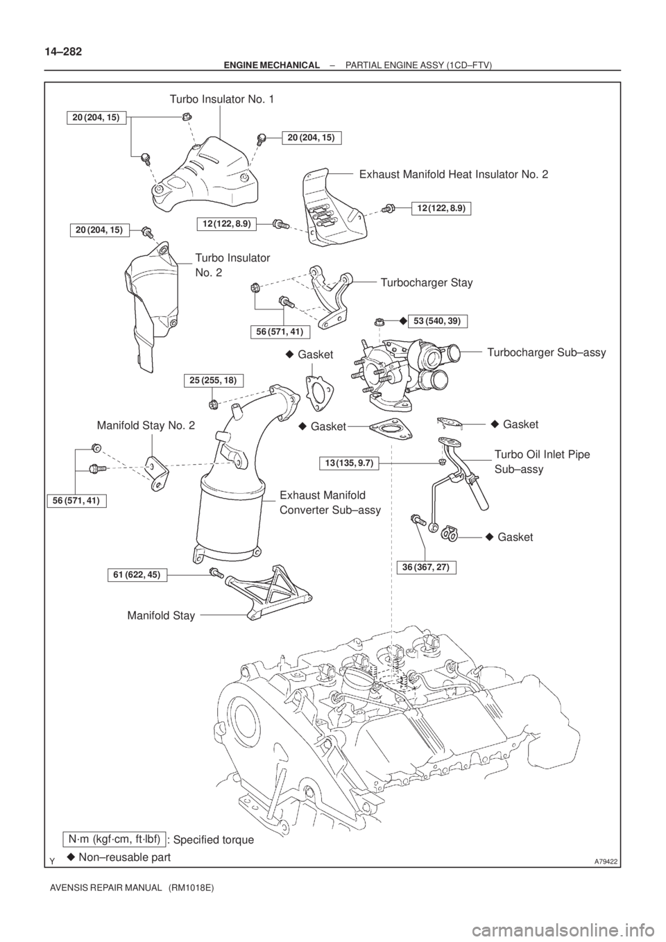
A79422
N´m (kgf´cm, ft´lbf)
: Specified torque
� Non±reusable part� Gasket
� Gasket � Gasket
20 (204, 15)
20 (204, 15)
53 (540, 39)
13 (135, 9.7)
36 (367, 27)61 (622, 45)
56 (571, 41)
25 (255, 18)
Turbo Insulator No. 1
Exhaust Manifold Heat Insulator No. 2
Turbocharger Stay
Turbocharger Sub±assy
Turbo Oil Inlet Pipe
Sub±assy
Manifold Stay Manifold Stay No. 2
Exhaust Manifold
Converter Sub±assy Turbo Insulator
No. 2
�
20 (204, 15)
12 (122, 8.9)
56 (571, 41)
� Gasket
12 (122, 8.9)
14±282
± ENGINE MECHANICALPARTIAL ENGINE ASSY (1CD±FTV)
AVENSIS REPAIR MANUAL (RM1018E)
Page 2241 of 5135
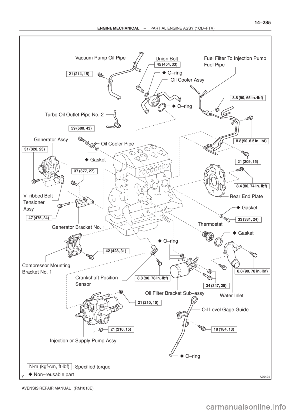
A79424
N´m (kgf´cm, ft´lbf)
: Specified torque
� Non±reusable part
8.8 (90, 65 in.�lbf)
8.8 (90, 6.5 in.�lbf)
8.4 (86, 74 in.�lbf)
21 (209, 15)
8.8 (90, 78 in.�lbf)
34 (347, 25)
18 (184, 13)21 (210, 15)
21 (210, 15)
42 (428, 31)
37 (377, 27)
59 (600, 43)
21 (214, 15)
45 (454, 33)
� O±ring
� O±ring
� Gasket
� O±ring
� O±ring
Vacuum Pump Oil Pipe
Union Bolt
Oil Cooler AssyFuel Filter To Injection Pump
Fuel Pipe
Rear End Plate
Crankshaft Position
Sensor
Thermostat
Water Inlet
Oil Level Gage Guide Oil Filter Bracket Sub±assy
Injection or Supply Pump Assy Compressor Mounting
Bracket No. 1Generator Bracket No. 1 V±ribbed Belt
Tensioner
AssyGenerator Assy
Oil Cooler Pipe
� Gasket
Turbo Oil Outlet Pipe No. 2
31 (320, 23)
� Gasket
33 (331, 24)
8.8 (90, 78 in.�lbf)
47 (475, 34)
± ENGINE MECHANICALPARTIAL ENGINE ASSY (1CD±FTV)
14±285
AVENSIS REPAIR MANUAL (RM1018E)
Page 2250 of 5135

140DD±03
A57063
Measure Point for Belt
Deflection and Tension
Alternator
Crankshaft Compressor
P/S P/S
Alternator Crankshaft
A/C equipped
A/C not equipped
A61173
B
A
14±266
±
ENGINE MECHANICAL ENGINE(1CD±FTV)
AVENSIS REPAIR MANUAL (RM1018E)
ENGINE(1CD±FTV)
INSPECTION
1.INSPECT COOLANT (See page 16±37)
2.INSPECT ENGINE OIL (See page 17±20)
3.INSPECT BATTERY (See page 19±26)
4. INSPECT AIR CLEANER FILTER ELEMENT SUB±ASSY 5. INSPECT DRIVE BELT
(a) Inspect vane pump V belt.(1) Measure the belt deflection
Pressing force: 98 N �m (10 kgf 22 lbf)
New belt
mm (in.)Used belt mm (in.)
A/C equipped9.5 to 11.5
(0.37 to 0.45)12.5 to 15.5
(0.49 to 0.61)
A/C not equipped10 to 12
(0.39 to 0.47)14 to 17
(0.55 to 0.67)
(2) Measure the belt tension
New belt
N (kgf, lbf)Used belt
N (kgf, lbf)
A/C equipped519 to 755
(53 to 77, 117 to 170)196 to 392
(20 to 40, 44 to 88)
A/C not equipped686 to 784
(70 to 80, 154 to 176)294 to 441
(30 to 45, 66 to 99)
NOTICE:
�Check the drive belt deflection at the specified point.
�When installing a new belt, set its tension value as
specified.
�When inspecting the belt which is used over 5 min-
utes, apply the specifications of ºUsed Belt.º
�When reinstalling the belt which is used over 5 min-
utes, adjust its deflection and tension to the medium
value in each specification of ºUsed Belt.º
�V±ribbed belt tension and deflection should be
checked after 2 revolutions of engine cranking.
�When using a belt tension gauge, confirm the accura-
cy by using a master gauge first.
(b) Inspect generator V belt. (1) Check that the tension indicator is within range A onthe auto tensioner scale.
If the tension is not within the A range, replace the belt with a
new one.
HINT:
When replacing the drive belt with a new one, the belt tension
should be within the B range.
Page 2252 of 5135

AVENSIS REPAIR MANUAL (RM1018E)
(2) Connect SST (compression gauge) to the SST (at-
tachment).
SST 09992±00025 (09992±")
A61174
SST
Compression Gauge
14±268
± ENGINE MECHANICALENGINE (1CD±FTV)
AVENSIS REPAIR MANUAL (RM1018E)
(2) Connect SST (compression gauge) to the SST (at-
tachment).
SST 09992±00025 (09992±00211)
(3) Fully open the throttle valve, and start the engine.
(4) While cranking the engine, measure the compres-
sion pressure.
NOTICE:
�Always use a fully charged battery to obtain engine
speed of 250 rpm or more.
�Check other cylinder compression pressure in the
same way.
�This measurement must be done in as short a time as
possible.
Compression pressure:
2,628 kPa (26.8 kgf/cm
2, 381 psi) or more
Minimum pressure:
2,157 kPa (22.0 kgf/cm
2, 312 psi) or more
Difference between each cylinder:
490 kPa (5.0 kgf/cm
2, 71 psi) or less
(5) If the cylinder compression is low, pour a small
amount of engine oil into the cylinder through the
glow plug hole and inspect again.
HINT:
�If adding oil raises the compression, there are chances of
the piston rings and/or cylinder bore wear or damage.
�If pressure stays low, a valve may be sticking or seating
improperly, or there may be leakage past the gasket.
Page 2253 of 5135

14±265
AVENSIS REPAIR MANUAL (RM1018E)
ENGINE REAR OIL SEAL(1AZ±FSE)
REPLACEMENT
1.REMOVE MANUAL TRANSAX")
141BS±01
A77421
Cut Position
A77422SST
±
ENGINE MECHANICAL ENGINE REAR OIL SEAL(1AZ±FSE)
14±265
AVENSIS REPAIR MANUAL (RM1018E)
ENGINE REAR OIL SEAL(1AZ±FSE)
REPLACEMENT
1.REMOVE MANUAL TRANSAXLE ASSY (M/T TRANSAXLE) (See page 41±24)
2.REMOVE AUTOMATIC TRANSAXLE ASSY (A/T TRANSAXLE) (See page 40±25)
3.REMOVE CLUTCH COVER ASSY (M/T TRANSAXLE) (See page 42±26)
4.REMOVE DRIVE PLATE AND RING GEAR OR FLYWHEEL (See page 14±204)
SST09213±54015 (91651±60855), 09330±00021
5.REMOVE ENGINE REAR OIL SEAL
(a)Using a knife, cut off the engine rear oil seal lip.
(b)Using a screwdriver with the tip wrapped in tape, pry outthe engine rear oil seal.
HINT:
After the removal, check if the crankshaft is not damaged.
If is damaged, smooth the surface with 400±grit sandpaper.
6.INSTALL ENGINE REAR OIL SEAL
(a)Apply MP grease to a new engine rear oil seal lip.
NOTICE:
Keep the lip off foreign materials.
(b)Using SST and a hammer, tap in the engine rear oil seal until its surface is flush with the engine rear oil seal retain-
er edge.
SST09223±15030, 09950±70010 (09951±07100)
NOTICE:
Wipe off extra grease on the crankshaft.
7.INSTALL DRIVE PLATE AND RING GEAR OR FLYWHEEL (See page 14±204) SST 09213±54015 (91651±60855), 09330±00021
8.INSTALL CLUTCH COVER ASSY (M/T TRANSAXLE) (See page 42±26)
9.INSTALL MANUAL TRANSAXLE ASSY (M/T TRANSAXLE) (See page 41±24)
10.INSTALL AUTOMATIC TRANSAXLE ASSY (A/T TRANSAXLE) (See page 40±25)
Page 2254 of 5135
141BR±01
A77339
A13697
SST
SST
A77381
SST
±
ENGINE MECHANICAL TIMING GEAR CASE OR TIMING CHAIN CASE OIL
SEAL(1AZ±FSE)14±263
AVENSIS REPAIR MANUAL (RM1018E)
TIMING GEAR CASE OR TIMING CHAIN CASE OIL
SEAL(1AZ±FSE)
REPLACEMENT
1.REMOVE FRONT WHEEL RH
2.REMOVE RADIATOR SUPPORT OPENING COVER
3.REMOVE ENGINE ROOM COVER SIDE
4.REMOVE ENGINE UNDER COVER RH
5.REMOVE ENGINE COVER SUB±ASSY NO.1
(a)Remove the 2 nuts and the engine cover No. 1.
6.REMOVE FAN AND GENERATOR V BELT (See page 14±185) SST 09249±63010
7. REMOVE CRANKSHAFT PULLEY
(a) Using SST, loosen the pulley bolt.SST 09213±54015 (91651±60855), 09330±00021
(b) Using SST, remove the crankshaft pulley. SST 09950±50013 (09951±05010, 09952±05010, 09953±05020, 09954±05021)

14±191
AVENSIS REPAIR MANUAL (RM1018E)
(h)Install the camshafts. (See page 14±240)
(i)Install the chain tensioner. (See page 14±240)
14.INSTALL CYLI")
14±263
AVENSIS REPAIR MANUAL (RM1018E)
TIMING GEAR CASE OR TIMING CHAIN CASE")