Page 2192 of 5135

14±233
AVENSIS REPAIR MANUAL (RM1018E)
52.INSTALL OIL PAN SUB±ASSY
NOTICE:
�Remov")
A77392
Seal Packing6mm
A64641
A77393
SST
A77394
Raise
Pin Hook
Push
±
ENGINE MECHANICAL CHAIN SUB±ASSY(1AZ±FSE)
14±233
AVENSIS REPAIR MANUAL (RM1018E)
52.INSTALL OIL PAN SUB±ASSY
NOTICE:
�Remove any oil from the contact surface.
�Install the oil pan within 3 minutes after applying seal
packing.
�Do not start the engine within 2 hours after installing.
(a)Remove any old packing (FIPG) material and be careful
not to drop any oil on the contact surface of the cylinder
block and oil pan.
(b)Apply a continuous bead (Diameter 3 mm to 4 mm (0.157 in.)) of seal packing as shown in the illustration, and install
the oil pan.
Seal packing: part No. 08826 ± 00080 or equivalent
(c)Install the oil pan with the 12 bolts and 2 nuts. Torque: 9.0 N �m (92 kgf �cm,80 in. �lbf)
53.INSTALL CRANKSHAFT POSITION SENSOR (See page 18±17) 54. INSTALL CRANKSHAFT PULLEY
(a) Using SST, tighten the set bolt.SST 09213±54015 (91651±60855), 09330±00021
Torque: 170 N �m (1,733 kgf �cm, 125 ft �lbf)
55. INSTALL CHAIN TENSIONER ASSY NO.1
(a) Release the ratchet pawl, fully push in the plunger and ap- ply the hook to the pin so that the plunger is located in
position.
Page 2194 of 5135

14±235
AVENSIS REPAIR MANUAL (RM1018E)
(b)Apply seal packing to the 2 locations as shown in the il-")
A77399
Seal Packing
A77346
AA
A AA
BB
C
C
Nut Nut
±
ENGINE MECHANICAL CHAIN SUB±ASSY(1AZ±FSE)
14±235
AVENSIS REPAIR MANUAL (RM1018E)
(b)Apply seal packing to the 2 locations as shown in the il-
lustration.
Seal Packing: Part No. 08826±00080 or equivalent
NOTICE:
�Remove any oil from the contact surface.
�Install the cylinder head cover within 5 minutes after
applying seal packing.
�Do not expose the seal to engine oil 2 hours after
installing.
(c)install the cylinder head cover with the 9 bolts and 2 nuts. Torque:
Nut 11 N �m (112 kgf �cm, 8 ft �lbf)
Bolt A 11 N �m (112 kgf �cm, 8 ft �lbf)
Bolt B 14 N �m (143 kgf �cm, 10 ft �lbf)
Bolt C 21 N �m (214 kgf �cm, 16 ft �lbf)
59.INSTALL COOLER BRACKET (LHD STEERING POSITION TYPE) Torque: 9.0 N �m (92 kgf �cm,80 in. �lbf)
60.INSTALL ENGINE SERVICE COVER BRACKET RH (RHD STEERING POSITION TYPE) Torque: 9.0 N �m (92 kgf �cm,80 in. �lbf)
61.INSTALL ENGINE WIRE
Torque: 7.0 N �m (71 kgf �cm,62 in. �lbf)
62.INSTALL OIL RESERVOIR BRACKET NO.1 Torque: 8.0 N �m (82 kgf �cm,71 in. �lbf)
63.INSTALL COOLER REFRIGERANT SUCTION HOSE NO.1 (LHD STEERING POSITION TYPE)
64.INSTALL RETURN TUBE SUB±ASSY
Torque: 8.0 N �m (82 kgf �cm,71 in. �lbf)
65.INSTALL IGNITION COIL ASSY Torque: 9.0 N �m (92 kgf �cm,80 in. �lbf)
66.INSTALL VANE PUMP ASSY
Torque: 37 N �m (377 kgf �cm,27 ft �lbf)
67.INSTALL EXHAUST PIPE ASSY FRONT (See page 15±7)
68.INSTALL GENERATOR ASSY (See page 19±20)
69.INSTALL FAN AND GENERATOR V BELT (See page 14±185) SST 09249±63010
70.INSTALL FUEL PUMP ASSY (See page 11±52)
71.INSTALL FUEL PIPE SUB±ASSY NO.1 (See page 11±52) SST 09023±12900
72.INSTALL FUEL TUBE SUB±ASSY (See page 11±30)
73.INSTALL FUEL PRESSURE PULSATION DAMPER ASSY (See page 11±52)
74. ADD ENGINE OIL
75. CHECK FOR ENGINE OIL LEAKS
76. CHECK FOR FUEL LEAKS
Page 2197 of 5135
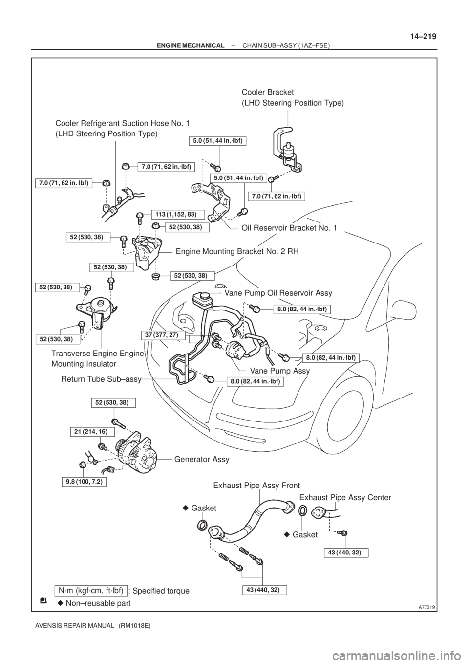
A77319
N´m (kgf´cm, ft´lbf)
: Specified torque
� Non±reusable part� GasketCooler Bracket
(LHD Steering Position Type)
113 (1,152, 83)
Cooler Refrigerant Suction Hose No. 1
(LHD Steering Position Type)
8.0 (82, 44 in.�lbf)
8.0 (82, 44 in.�lbf)
8.0 (82, 44 in.�lbf)
52 (530, 38)
Transverse Engine Engine
Mounting Insulator
Vane Pump Oil Reservoir Assy
Return Tube Sub±assy
52 (530, 38)
21 (214, 16)
9.8 (100, 7.2)
Generator Assy
Exhaust Pipe Assy Front
43 (440, 32)
� Gasket
43 (440, 32)
7.0 (71, 62 in.�lbf)
52 (530, 38)
7.0 (71, 62 in.�lbf)
Oil Reservoir Bracket No. 1
52 (530, 38)
52 (530, 38)
Engine Mounting Bracket No. 2 RH
7.0 (71, 62 in.�lbf)
5.0 (51, 44 in.�lbf)
5.0 (51, 44 in.�lbf)
52 (530, 38)
Exhaust Pipe Assy Center
52 (530, 38)
Vane Pump Assy
37 (377, 27)
± ENGINE MECHANICALCHAIN SUB±ASSY (1AZ±FSE)
14±219
AVENSIS REPAIR MANUAL (RM1018E)
Page 2199 of 5135
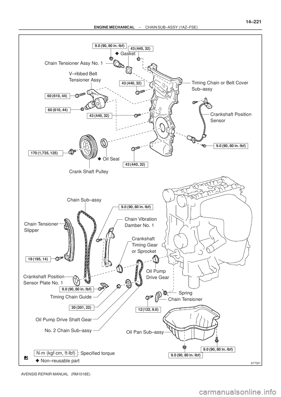
A77321
N´m (kgf´cm, ft´lbf)
: Specified torque
� Non±reusable part
43 (440, 32)
� Gasket
Chain Tensioner Assy No. 1
Timing Chain or Belt Cover
Sub±assy
Crankshaft Position
Sensor
9.0 (90, 80 in.�lbf)
V±ribbed Belt
Tensioner Assy
60 (610, 44)
60 (610, 44)
43 (440, 32)
43 (440, 32)
170 (1,735, 125)
Crank Shaft Pulley
� Oil Seal
43 (440, 32)
Chain Sub±assy
Chain Tensioner
Slipper
Chain Vibration
Damber No. 1
Crankshaft
Timing Gear
or Sprocket
19 (195, 14)
Crankshaft Position
Sensor Plate No. 1
Timing Chain Guide
Oil Pump
Drive Gear
12 (122, 9.0)
Spring
Chain Tensioner
Oil Pump Drive Shaft Gear
Oil Pan Sub±assy
9.0 (90, 80 in.�lbf)
9.0 (90, 80 in.�lbf)
9.0 (90, 80 in.�lbf)
30 (301, 22)
No. 2 Chain Sub±assy
9.0 (90, 80 in.�lbf)
9.0 (90, 80 in.�lbf)
± ENGINE MECHANICALCHAIN SUB±ASSY (1AZ±FSE)
14±221
AVENSIS REPAIR MANUAL (RM1018E)
Page 2200 of 5135

AVENSIS REPAIR MANUAL (RM1018E)
REPLACEMENT
1.DISCHARGE FUEL SYSTEM PRESSURE (See page 11±33)
2.REMOVE FRONT WHEEL")
141BM±01
A77339
A77301
14±204
±
ENGINE MECHANICAL PARTIAL ENGINE ASSY(1AZ±FSE)
AVENSIS REPAIR MANUAL (RM1018E)
REPLACEMENT
1.DISCHARGE FUEL SYSTEM PRESSURE (See page 11±33)
2.REMOVE FRONT WHEELS
3.REMOVE RADIATOR SUPPORT OPENING COVER
4.REMOVE ENGINE ROOM COVER SIDE
5.REMOVE ENGINE UNDER COVER RH
6.REMOVE ENGINE UNDER COVER LH
7.DRAIN COOLANT (See page 16±31)
8.DRAIN ENGINE OIL
(a)Install a new gasket and the drain plug after draining engine oil. Torque: 25 N �m (255 kgf �cm,18 ft �lbf)
9.DRAIN MANUAL TRANSAXLE OIL (M/T TRANSAXLE) Torque: 49 N �m (500 kgf �cm,36 ft �lbf)
10.DRAIN AUTOMATIC TRANSAXLE FLUID (A/T TRANSAXLE) (See page 40±2)
11.REMOVE ENGINE COVER SUB±ASSY NO.1
(a)Remove the 2 nuts and the cylinder head cover No. 1.
12.DISCONNECT RADIATOR HOSE INLET
13.DISCONNECT RADIATOR HOSE OUTLET 14.SEPARATE RADIATOR RELAY BLOCK
(a)Remove the 2 bolts and separate the radiator relay block.
15.SEPARATE COOLER REFRIGERANT SUCTION HOSE NO.1 (RHD STEERING POSITION TYPE)
(a)Remove the bolt and separate the suction hose No. 1.
16.REMOVE RADIATOR ASSY (See page 16±36)
17.REMOVE FAN AND GENERATOR V BELT (See page 14±185)
18.REMOVE GENERATOR ASSY (See page 19±20)
19. REMOVE COMPRESSOR AND MAGNETIC CLUTCH
(a) Remove the 4 bolts and separate the compressor and magnetic clutch.
HINT:
Secure the hoses off to the side instead of detaching.
20. REMOVE BATTERY
Page 2202 of 5135

AVENSIS REPAIR MANUAL (RM1018E)
25.SEPARATE VANE PUMP OIL RESERVOIR ASSY 26.REMOVE OIL RESERVOIR BRACKET NO.1
(a)Remov")
A77308
A77303
A77340
14±206
±
ENGINE MECHANICAL PARTIAL ENGINE ASSY(1AZ±FSE)
AVENSIS REPAIR MANUAL (RM1018E)
25.SEPARATE VANE PUMP OIL RESERVOIR ASSY 26.REMOVE OIL RESERVOIR BRACKET NO.1
(a)Remove the 2 bolts and the oil reservoir bracket No. 1.
27.SEPARATE COOLER REFRIGERANT SUCTION HOSENO.1 (LHD STEERING POSITION TYPE)
(a)Remove the 2 nuts and separate the suction hose.
28.REMOVE COOL ER BRACKET (LHD STEER ING
POSITION TYPE)
(a)Remove the nut and separate the cooler bracket.
29.REMOVE ENGINE SERVICE COVER BRACKET RH (RHD STEERING POSITION TYPE)
(a)Remove the bolt and the service cover bracket RH.
30.DISCONNECT HEATER INLET WATER HOSE
31.DISCONNECT HEATER OUTLET WATER HOSE
32.REMOVE CHARCOAL CANISTER ASSY
33.DISCONNECT FUEL TUBE SUB±ASSY (See page 11±30)
34. DISCONNECT UNION TO CONNECTOR TUBE HOSE
35.REMOVE FLOOR PANEL BRACE FRONT (See page 15±7)
36.REMOVE EXHAUST PIPE ASSY CENTER (See page 15±7)
37.REMOVE EXHAUST PIPE ASSY FRONT (See page 15±7)
38.REMOVE FRONT AXLE HUB LH NUT (See page 30±6) SST 09330±00030
Page 2206 of 5135

AVENSIS REPAIR MANUAL (RM1018E)
61.SEPARATE VANE PUMP ASSY
(a)Disconnect the PS oil pressure switch connector.
(b)Remove")
A77331
SST
A77353
14±210
±
ENGINE MECHANICAL PARTIAL ENGINE ASSY(1AZ±FSE)
AVENSIS REPAIR MANUAL (RM1018E)
61.SEPARATE VANE PUMP ASSY
(a)Disconnect the PS oil pressure switch connector.
(b)Remove the 2 bolts and separate the vane pump from the engine.
62.REMOVE STARTER ASSY (See page 19±12)
63. REMOVE FRONT SUSPENSION CROSSMEMBER W/CENTER MEMBER
(a) Remove the through bolt and nut from the engine mounting insulator FR.
(b) Remove the through bolt and nut from the engine mounting insulator RR.
64.REMOVE FRONT DRIVE SHAFT ASSY LH (See page 30±6)
65.REMOVE FRONT DRIVE SHAFT ASSY RH (See page 30±6)
66.REMOVE MANUAL TRANSAXLE ASSY (M/T TRANSAXLE) (See page 41±24)
67.REMOVE AUTOMATIC TRANSAXLE ASSY (A/T TRANSAXLE) (See page 40±25)
68.REMOVE CLUTCH COVER ASSY (M/T TRANSAXLE) (See page 42±26)
69.REMOVE CLUTCH DISC ASSY (M/T TRANSAXLE) (See page 42±26) 70. REMOVE DRIVE PLATE AND RING GEAR ORFLYWHEEL
(a) Using SST, fix the crankshaft pulley and remove the drive plate and ring gear or flywheel.
SST 09213±54015 (91651±60855), 09330±00021
71. REMOVE CAMSHAFT TIMING OIL CONTROL VALVE ASSY
(a) Remove the bolt, O±ring and the camshaft timing oil control valve.
72. REMOVE THROTTLE BODY BRACKET
(a) Separate the engine wire.
(b) Remove the 4 bolts and the throttle body bracket.
73.REMOVE THROTTLE BODY ASSY (See page 10±44)
74. REMOVE FUEL PRESSURE PULSATION DAMPER ASSY
75. DISCONNECT FUEL TUBE SUB±ASSY
76.REMOVE FUEL PIPE SUB±ASSY NO.1 (See page 11±52)
77.REMOVE FUEL PUMP ASSY (See page 11±52)
78. REMOVE WATER BY±PASS HOSE 79. REMOVE INTAKE MANIFOLD
(a) Remove the 5 bolts and 2 nuts.
(b) Remove the intake manifold and the insulator.
Page 2207 of 5135

14±211
AVENSIS REPAIR MANUAL (RM1018E)
80.REMOVE INTAKE AIR CONTROL VALVE ASSY
(a)Remove the intake air control valve and a g")
A32676
A77350
A52497
±
ENGINE MECHANICAL PARTIAL ENGINE ASSY(1AZ±FSE)
14±211
AVENSIS REPAIR MANUAL (RM1018E)
80.REMOVE INTAKE AIR CONTROL VALVE ASSY
(a)Remove the intake air control valve and a gasket.
81.REMOVE SURGE TANK STAY NO.1
(a)Remove the 3 bolts and the surge tank stay.
82.REMOVE INTAKE MANIFOLD INSULATOR NO.2
83.REMOVE NOZZLE HOLDER CLAMP
84.REMOVE FUEL DELIVERY PIPE SUB±ASSY (See page 11±42)
85.REMOVE FUEL INJECTOR ASSY (See page 11±42)
86. REMOVE V±RIBBED BELT TENSIONER ASSY
(a) Remove the bolt and nut, and then detach the V±ribbedbelt tensioner.
87. REMOVE IGNITION COIL ASSY
(a) Remove the 4 bolts and the ignition coils.
88. REMOVE EXHAUST MANIFOLD HEAT INSULATOR NO.1
(a) Remove the 3 bolts and the exhaust manifold heat insulator. 89. REMOVE EXHAUST MANIFOLD CONVERTERSUB±ASSY
(a) Remove the 2 bolts and 2 nuts, then detach the No. 1 and No. 2 exhaust manifold stay.
(b) Remove the 5 nuts, the exhaust manifold converter and gasket.
90. REMOVE OIL LEVEL GAGE SUB±ASSY
91. REMOVE OIL LEVEL GAGE GUIDE
92. REMOVE WATER INLET
(a) Remove the 2 nuts and the water inlet.
93. REMOVE THERMOSTAT