Page 150 of 5135
031HF±01
03±36
± SERVICE SPECIFICATIONSREAR SUSPENSION
AVENSIS REPAIR MANUAL (RM1018E)
REAR SUSPENSION
SERVICE DATA
Toe±in (total)
Normal package:
Rough road package:
0�18' � 12' (0.3� � 0.2�, 3.0 � 2.0 mm, 0.12 � 0.08 in.)
0�18' � 12' (0.3� � 0.2�, 3.0 � 2.0 mm, 0.12 � 0.08 in.)
Rear wheel align-
mentCamber
Normal package:
Rough road package:
Right±left error
±0���' � 30' (±0.9� � 0.5�)
±0�30' � 30' (±0.5� � 0.5�)
30' (0.5�) or less
Page 151 of 5135
0313A±05
± SERVICE SPECIFICATIONSFRONT SUSPENSION
03±35
AVENSIS REPAIR MANUAL (RM1018E)
TORQUE SPECIFICATION
Part TightenedN�mkgf�cmft�lbf
Tie rod end lock nut7475555
Steering knuckle x Shock absorber2202,240162
Hub nut1031,05076
Suspension support x Piston rod4747935
Suspension support x Body3939829
Suspension crossmember sub±assy x Body1331,36098
Suspension crossmember sub±assy x Engine mounting insulator8081659
Suspension crossmember sub±assy x Center member9697971
Suspension member brace x Body Bolt A:
Bolt B:80
133816
1,36059
98
Speed sensor wire harness bracket set bolt1919214
Stabilizer bracket No.1 x Suspension crossmember (w/o HID)1919414
Stabilizer bracket No.1 x Suspension crossmember (w/ HID) Bolt A:
Bolt B:5.4
1955
19448
14
Stabilizer bar link set nut7475555
Lower suspension arm x Lower ball joint8990866
Lower ball joint x Steering knuckle1031,05076
Lower suspension arm x Suspension crossmember1371,400101
Page 152 of 5135

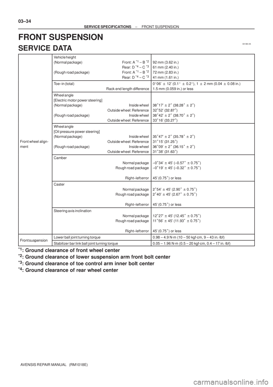
0313B±05
03±34
± SERVICE SPECIFICATIONSFRONT SUSPENSION
AVENSIS REPAIR MANUAL (RM1018E)
FRONT SUSPENSION
SERVICE DATA
Vehicle height
(Normal package) Front: A *1
± B *2
Rear: D *4 ± C *3
(Rough road package) Front: A *1
± B *2
Rear: D *4 ± C *3
92 mm (3.62 in.)
61 mm (2.40 in.)
72 mm (2.83 in.)
41 mm (1.61 in.)
Toe±in (total)
Rack end length difference0�06' � 12' (0.1� � 0.2�), 1 � 2 mm (0.04 � 0.08 in.)
1.5 mm (0.059 in.) or less
Wheel angle
[Electric motor power steering]
(Normal package) Inside wheel
Outside wheel: Reference
(Rough road package) Inside wheel
Outside wheel: Reference
��
17' � 2
������
� �
�
32
52' ������
�
��
42' � 2
������
� �
�
33
16' ������
�
Front wheel align-
ment
Wheel angle
[Oil pressure power steering]
(Normal package) Inside wheel
Outside wheel: Reference
(Rough road package) Inside wheel
Outside wheel: Reference
�
47' � 2
�� ���
� �
�
31
15' �����
�
�
09' � 2
��
��
� �
�
31
38' ����
�
�
Camber
Normal package
Rough road package
Right±left error
±0
34' � 45' (±0.57
� 0.75
)
±0
19' � 45' (±0.32
� 0.75
)
45' (0.75
) or less
Caster
Normal package
Rough road package
Right±left error
�
54' � 45' (2.90
� 0.75
)
�
40' � 45' (2.67
� 0.75
)
45' (0.75
) or less
Steering axis inclination
Normal package
Rough road package
Right±left error
12
27' � 45' (12.45
� 0.75
)
11
56' � 45' (11.93
� 0.75
)
45' (0.75
) or less
Front suspensionLower ball joint turning torque0.98 ± 4.9 N´m (10 ± 50 kgf´cm, 9 ± 43 in.´lbf)Front suspensionStabilizer bar link ball joint turning torque0.05 ± 1.96 N´m (0.5 ± 20 kgf´cm, 0.4 ± 17 in.´lbf)
*1: Ground clearance of front wheel center
*2: Ground clearance of lower suspension arm front bolt center
*3: Ground clearance of toe control arm inner bolt center
*4: Ground clearance of rear wheel center
Page 165 of 5135
031HC±01
± SERVICE SPECIFICATIONSLIGHTING
03±65
AVENSIS REPAIR MANUAL (RM1018E)
LIGHTING
TORQUE SPECIFICATION
Part TightenedN�mkgf�cmft�lbf
Height control sensor sub±assy Fr RH x Body7.98170 in.�lbf
Height control sensor sub±assy Fr RH x Stabilizer bar rear5.85951 in.�lbf
Height control sensor sub±assy Rr RH x Suspension menber7.98170 in.�lbf
Height control sensor sub±assy Rr RH x Upper control arm assy5.85951 in.�lbf
Page 170 of 5135

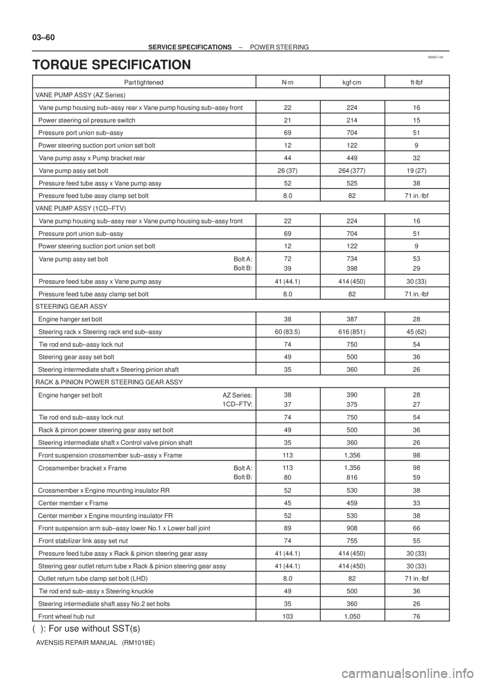
030G7±04
03±60
± SERVICE SPECIFICATIONSPOWER STEERING
AVENSIS REPAIR MANUAL (RM1018E)
TORQUE SPECIFICATION
Part tightenedN�mkgf�cmft�lbf
VANE PUMP ASSY (AZ Series)
Vane pump housing sub±assy rear x Vane pump housing sub±assy front2222416
Power steering oil pressure switch2121415
Pressure port union sub±assy6970451
Power steering suction port union set bolt121229
Vane pump assy x Pump bracket rear4444932
Vane pump assy set bolt26 (37)264 (377)19 (27)
Pressure feed tube assy x Vane pump assy5252538
Pressure feed tube assy clamp set bolt8.08271 in.�lbf
VANE PUMP ASSY (1CD±FTV)
Vane pump housing sub±assy rear x Vane pump housing sub±assy front2222416
Pressure port union sub±assy6970451
Power steering suction port union set bolt121229
Vane pump assy set bolt Bolt A:
Bolt B:72
39734
39853
29
Pressure feed tube assy x Vane pump assy41 (44.1)414 (450)30 (33)
Pressure feed tube assy clamp set bolt8.08271 in.�lbf
STEERING GEAR ASSY
Engine hanger set bolt3838728
Steering rack x Steering rack end sub±assy60 (83.5)616 (851)45 (62)
Tie rod end sub±assy lock nut7475054
Steering gear assy set bolt4950036
Steering intermediate shaft x Steering pinion shaft3536026
RACK & PINION POWER STEERING GEAR ASSY
Engine hanger set bolt AZ Series:
1CD±FTV:38
37390
37528
27
Tie rod end sub±assy lock nut7475054
Rack & pinion power steering gear assy set bolt4950036
Steering intermediate shaft x Control valve pinion shaft3536026
Front suspension crossmember sub±assy x Frame11 31,35698
Crossmember bracket x Frame Bolt A:
Bolt B:11 3
801,356
81698
59
Crossmember x Engine mounting insulator RR5253038
Center member x Frame4545933
Center member x Engine mounting insulator FR5253038
Front suspension arm sub±assy lower No.1 x Lower ball joint8990866
Front stabilizer link assy set nut7475555
Pressure feed tube assy x Rack & pinion steering gear assy41 (44.1)414 (450)30 (33)
Steering gear outlet return tube x Rack & pinion steering gear assy41 (44.1)414 (450)30 (33)
Outlet return tube clamp set bolt (LHD)8.08271 in.�lbf
Tie rod end sub±assy x Steering knuckle4950036
Steering intermediate shaft assy No.2 set bolts3536026
Front wheel hub nut1031,05076
( ): For use without SST(s)
Page 824 of 5135

BR3893
Malfunction Code (Example Code 72 76)
ON
OFF
0.5 sec. 0.5 sec.1.5 sec.
0.5 sec.2.5 sec.
0.5 sec. 72 7 6
4 sec.
Repeat 05±764
± DIAGNOSTICSABS WITH EBD & BA & TRC & VSC SYSTEM
AVENSIS REPAIR MANUAL (RM1018E)
�If 2 or more DTCs are detected at the same time, the low-
est numbered code is displayed first.
(f) After the check, disconnect the SST from terminal Ts and
CG, Tc and CG of DLC3 and turn the ignition switch to
OFF.
SST 09843±19040
6. With using hand±held tester:
ABS SENSOR SIGNAL CHECK (TEST MODE)
NOTICE:
After replacing the steering angle sensor and/or ECU, perform zero point calibration of the steering
angle sensor or system decision (When replacing the ECU) (See step 7.).
HINT:
If the ignition switch is turned from ON to ACC or LOCK during test mode, the DTCs will be erased.
(a) Hook up the hand±held tester to the DLC3.
(b) Perform step 5. (c) to (d) on the previous page.
(c) Read the DTC by following the prompts on the tester screen.
HINT:
Please refer to the hand±held tester operator's manual for further details.
7. STEERING ANGLE SENSOR ZERO POINT CALIBRATION
NOTICE:
When replacing the steering angle sensor with column assembly or ECU, Engine and ECT ECU (A/T),
Engine ECU (M/T) or when adjusting the front wheel alignment or steering wheel center point in ac-
cordance with the removing or installing or replacing the suspension, axle or steering parts, make
sure to perform steering angle sensor zero point calibration.
(a) Using SST, connect terminals Ts and CG of the DLC3
.
SST 09843±18040
(b) Turn the ignition switch ON and keep the shift lever at P range.
(c) Make sure the steering off center angle is less than �3� when assembling the steering wheels (Smaller
value is desirable).
(d) Press the TRC OFF switch and hold it.
(e) Check that the following conditions are satisfied.
HINT:
�Engine warning light comes on.
�ABS warning light is blinking.
(f) Depress the brake pedal 3 times or more within 2 seconds.
Page 2047 of 5135

A64005
±
ENGINE MECHANICAL PARTIAL ENGINE ASSY (1ZZ±FE/3ZZ±FE)
14±31
AVENSIS REPAIR MANUAL (RM1018E)
40.REMOVE GENERATOR ASSY (See page 19±7)
41. SEPARATE COMPRESSOR AND MAGNETIC CLUTCH (W/ AIR CONDITIONING)
HINT:
�Secure the compressor and hoses off to the side instead of discharging the A/C system.
�1ZZ±FE (See page 55±74)
�3ZZ±FE (See page 55±70)
42. REMOVE COLUMN HOLE COVER SILENCER SHEET
(a) Remove the 2 clips and the column hole cover silencer sheet.
43.SEPARATE STEERING INTERMEDIATE SHAFT (See page 50±9)
44.REMOVE FRONT DOOR SCUFF PLATE RH (See page 71±11)
45.REMOVE COWL SIDE TRIM BOARD RH (See page 71±11)
46. REMOVE FRONT FLOOR FOOTREST
47. REMOVE FLOOR PANEL BRACE FRONT
(a) Remove the 2 nuts and the floor panel brace front.
48.REMOVE EXHAUST PIPE ASSY FRONT (See page 15±2)
49.REMOVE FRONT AXLE HUB LH NUT (See page 30±6)
SST 09930±00010
50. REMOVE FRONT AXLE HUB RH NUT SST 09930±00010
HINT:
Perform the same procedure as above on the opposite side.
51.SEPARATE TIE ROD END SUB±ASSY LH (See page 30±6)
SST 09628±62011
52. SEPARATE TIE ROD END SUB±ASSY RH SST 09628±62011
HINT:
Perform the same procedure as above on the opposite side.
53.SEPARATE FRONT STABILIZER LINK ASSY LH (See page 30±6)
54. SEPARATE FRONT STABILIZER LINK ASSY RH
HINT:
Perform the same procedure as above on the opposite side.
55.SEPARATE FRONT SUSPENSION ARM SUB±ASSY LOWER NO.1 LH (See page 30±6)
56. SEPARATE FRONT SUSPENSION ARM SUB±ASSY LOWER NO.1 RH
HINT:
Perform the same procedure as above on the opposite side.
57.SEPARATE FRONT AXLE ASSY LH (See page 30±6)
58. SEPARATE FRONT AXLE ASSY RH
HINT:
Perform the same procedure as above on the opposite side.
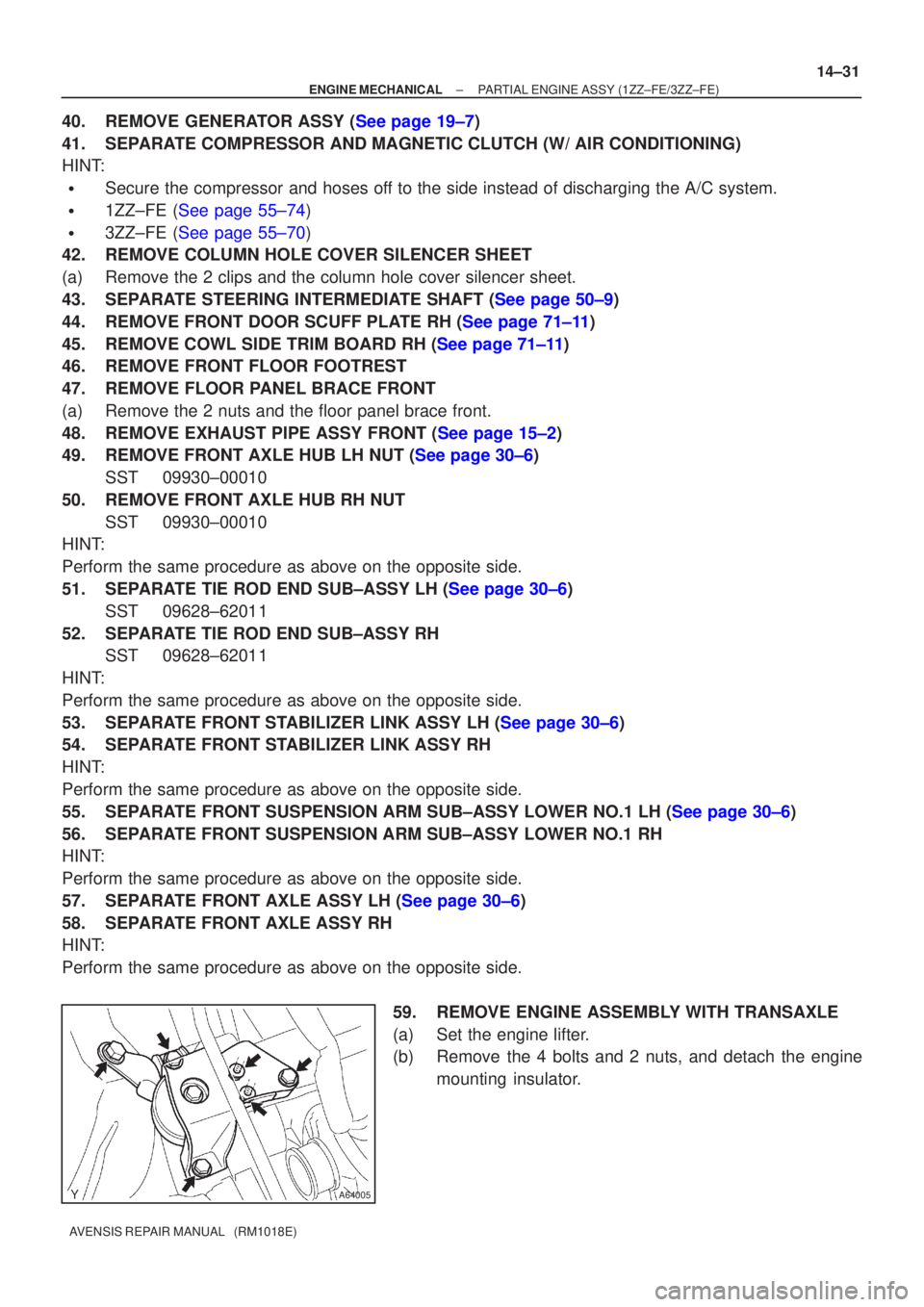
59. REMOVE ENGINE ASSEMBLY WITH TRANSAXLE
(a) Set the engine lifter.
(b) Remove the 4 bolts and 2 nuts, and detach the enginemounting insulator.
Page 2048 of 5135
A76715
A76717
A76716
A62830Front SideRear Side 14±32
± ENGINE MECHANICALPARTIAL ENGINE ASSY (1ZZ±FE/3ZZ±FE)
AVENSIS REPAIR MANUAL (RM1018E)
(c) Remove the through bolt and nut, detach the engine
mounting insulator from the vehicle.
(d) Remove the 2 bolts and 2 nuts as shown in the illustration.
(e) Remove the 8 bolts and the front suspension member
brace rear RH and LH.
(f) Carefully remove the engine with transaxle from the en-
gine compartment.
(g) Install the engine hanger No. 1 (12281±15040) and the
bolt (91512±B1016).
Torque: 38 N�m (387 kgf�cm, 28 ft�lbf)
(h) Install the engine hanger (12281±22021) and the bolt
(91512±B1016).
Torque: 38 N�m (387 kgf�cm, 28 ft�lbf)
HINT:
Securely install the front engine hanger (12281±22021) and the
rear engine hanger No. 1 (12281±15040) to the engine assem-
bly.
(i) Attach the engine sling and hang the engine with the
chain block.