Page 2326 of 5135

AVENSIS REPAIR MANUAL (RM1018E)
(i)Attach the engine sling and hang the engine with the chain block.
44.REMOVE FRO")
A62711
A79180
A61186
SST
14±290
±
ENGINE MECHANICAL PARTIAL ENGINE ASSY(1CD±FTV)
AVENSIS REPAIR MANUAL (RM1018E)
(i)Attach the engine sling and hang the engine with the chain block.
44.REMOVE FRONT SUSPENSION CROSSMEMBER SUB±ASSY
(a)Remove the through bolt and nut, detach the engine mounting insulator FR from the engine mounting bracket.
(b)Remove the through bolt, detach the engine mounting in- sulator RR from the suspension crossmember.
(c)Separate the engine and transaxle assembly from the suspension crossmember and engine mounting member.
45.REMOVE STARTER ASSY (See page 19±24)
46.REMOVE MANUAL TRANSAXLE (See page 41±33)
47.REMOVE CLUTCH DISC ASSY (See page 42±26) 48. REMOVE FLYWHEEL SUB±ASSY
(a) Hold the crank shaft with SST.SST 09213±54015 (90105±08076), 09330±00021
(b) Using a torx socket wrench (T55), remove the 8 torx
screws and the flywheel.
49. REMOVE REAR END PLATE
(a) Remove the 2 bolts and the rear end plate.
50. REMOVE DRIVE SHAFT BEARING BRACKET
51. REMOVE ENGINE MOUNTING BRACKET FR
52. REMOVE ENGINE MOUNTING BRACKET RR
53.REMOVE GLOW PLUG ASSY (See page 19±33)
54.REMOVE GENERATOR V BELT (See page 14±269)
55.REMOVE CRANKSHAFT PULLEY (See page 14±307) SST 09213±54015 (90105±08076), 09330±00021, 09950±50013 (0995\
1±05010, 09952±05010, 09953±05020, 09954±05031)
Page 2337 of 5135

14±301
AVENSIS REPAIR MANUAL (RM1018E)
(d)Using several steps, install and tighten the 8 screws with
a")
A79183
2
1
3
4
5
6
7
8
A79180
A62711
A59792
±
ENGINE MECHANICAL PARTIAL ENGINE ASSY(1CD±FTV)
14±301
AVENSIS REPAIR MANUAL (RM1018E)
(d)Using several steps, install and tighten the 8 screws with
a torx socket wrench (T55) uniformly in the sequence
shown in the illustration.
Torque: 71 N �m (720 kgf �cm, 52 ft �lbf)
166.INSTALL CLUTCH DISC ASSY (See page 42±26) SST 09301±00210
167.INSTALL MANUAL TRANSAXLE (See page 41±33)
168.INSTALL STARTER ASSY (See page 19±24)
169. INS TALL FRO NT SUSPENSION CROSSMEMBER
SUB±ASSY
(a) Attach the engine and the transaxle assembly to the sus- pension crossmember and engine mounting member.
(b) Install the bolt which is used to secure the rear engine
mounting bracket to the mounting insulator.
Torque: 87 N �m (887 kgf �cm, 64 ft �lbf)
(c) Install the bolt which is used to secure the front engine mounting bracket to the mounting insulator.
Torque: 52 N �m (530 kgf �cm, 38 ft �lbf)
170. INSTALL ENGINE ASSEMBLY WITH TRANSAXLE
(a) Set the engine assembly with transaxle on the engine lift-
er.
(b) Temporarily, install the suspension crossmember with the 2 bolts and 2 nuts.
(c) Install the engine mounting insulator LH.
Torque: 80 N �m (816 kgf �cm, 59 ft �lbf)
(d) Install the engine mounting insulator RH. Torque: 52 N �m (530 kgf �cm, 38 ft �lbf)
Page 2338 of 5135

AVENSIS REPAIR MANUAL (RM1018E)
(e)Install the front suspension crossmember with the 2 bolts and 2 nuts.
Tor")
A59792
BB
AA
A59793
AA
BBBBB
B
14±302
±
ENGINE MECHANICAL PARTIAL ENGINE ASSY(1CD±FTV)
AVENSIS REPAIR MANUAL (RM1018E)
(e)Install the front suspension crossmember with the 2 bolts and 2 nuts.
Torque:
45 N�m (459 kgf �cm, 33 ft �lbf) for bolt A
133 N �m (1,356 kgf �cm, 98 ft �lbf) for nut B
(f)Install the front suspension member brace LH and RH with the 8 bolts.
Torque:
133 N �m (1,356 kgf �cm, 98 ft �lbf) for bolt A
80 N �m (816 kgf �cm, 59 ft �lbf) for nut B
NOTICE:
After installing the crossmember, check that the position-
ing holes on the crossmember and the vehicle are aligned.
171.INSTALL FRONT DRIVE SHAFT ASSY LH (See page 30±6)
HINT:
Perform the same procedure as above on the opposite side.
172.INSTALL FRONT SUSPENSION ARM SUB±ASSY LOWER NO.1 LH (See page 26±21)
HINT:
Perform the same procedure as above on the opposite side.
173.INSTALL STEERING INTERMEDIATE SHAFT ASSY NO.2 (See page 51±36)
174.INSTALL FRONT STABILIZER LINK ASSY LH (See page 26±26)
HINT:
Perform the same procedure as above on the opposite side. SST 99999±70037
175.INSTALL TIE ROD END SUB±ASSY LH (See page 30±6)
HINT:
Perform the same procedure as above on the opposite side.
176.INSTALL FRONT AXLE HUB LH NUT (See page 30±6)
HINT:
Perform the same procedure as above on the opposite side.
177. INSTALL RETURN TUBE SUB±ASSY Torque: 8.0 N �m (82 kgf �cm, 71 in. �lbf)
178.INSTALL EXHAUST PIPE ASSY FRONT (See page 15±10)
179.INSTALL FLOOR PANEL BRACE FRONT (See page 15±10)
180. INSTALL COMPRESSOR AND MAGNETIC CLUTCH (W/ AIR CONDITIONING) (See page 55±86)
181.ADJUST V (COOLER COMPRESSOR TO CRANKSHAFT PULLEY) BELT NO.1 (See page 14±269 )
182.INSTALL CLUTCH RELEASE CYLINDER ASSY (See page 42±17)
183.INSTALL CLUTCH ACCUMULATOR ASSY (See page 42±17) SST 09023±00100
Page 2459 of 5135
260DP±01
F44614
Front Shock Absorber with Coil Spring
Front Stabilizer Link Assy LH
47 (479, 35)
220 (2,240, 162)
74 (755, 55)
19 (194, 14)
Speed Sensor
Front LH
Front Flexible Hose
Front Suspension Support Dust Cover LH
Front Suspension Support Sub±assy LH
Front Suspension
Support LH Dust Seal
Front Coil Spring
Seat Upper LH
Front Axle Assy
Front Coil Spring Insulator Upper LH
Front Coil Spring LH
N�m (kgf�cm, ft�lbf) : Specified torque
�Non±reusable part
Front Spring
Bumper LH
Front Coil
Spring Insulator
Lower LH
Shock Absorber
Assy Front LH
39 (398, 29)
� 26±2
± FRONT SUSPENSIONFRONT SUSPENSION
AVENSIS REPAIR MANUAL (RM1018E)
FRONT SUSPENSION
COMPONENTS
Page 2460 of 5135
F44615
Rack & Pinion Power
Steering Gear Assy
49 (500, 36)
Tie Rod End Sub±assy LH
Front Stabilizer Link Assy RH
Transverse Engine
Engine Mounting Insulator
Front Stabilizer Link Assy LH
Front Suspension
Crossmember Sub±assy
Front Suspension
Member Body Mounting
Stopper FR
133 (1,360, 98)
137 (1,400, 101)
Body Mounting Stopper Rear
52 (530, 38)
80 (816, 59)
74 (755, 55)
Front Suspension
Member Brace
Rear LH
80 (816, 59)
133 (1,360, 98)
Cotter Pin
49 (500, 36)
89 (908, 66)
Front Suspension Arm
Sub±assy Lower No.1 LH
80 (816, 59)
133 (1,360, 98)
80 (816, 59)
Front Suspension
Member Brace
Rear RH
133 (1,360, 98)
137 (1,400, 101)
N�m (kgf�cm, ft�lbf) : Specified torque
�Nblt
�Non±reusable part�
Engine Mounting Member
Sub±assy Center
96 (979, 71)
± FRONT SUSPENSIONFRONT SUSPENSION
26±3
AVENSIS REPAIR MANUAL (RM1018E)
Page 2461 of 5135
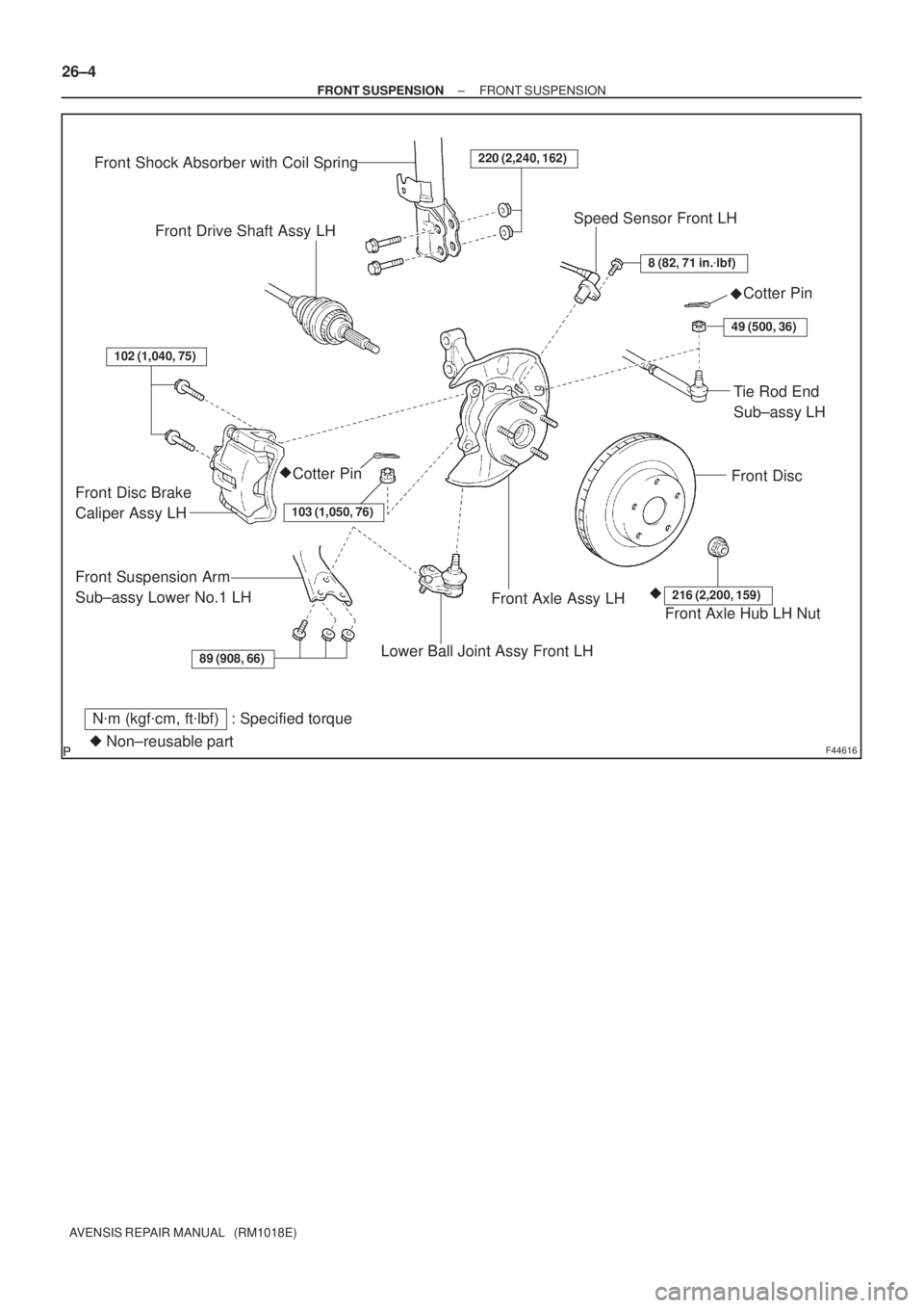
F44616
89 (908, 66)
102 (1,040, 75)
220 (2,240, 162)
8 (82, 71 in.�lbf)
49 (500, 36)
103 (1,050, 76)
216 (2,200, 159)
Front Shock Absorber with Coil Spring
Front Drive Shaft Assy LHSpeed Sensor Front LH
Cotter Pin
Front Disc
Tie Rod End
Sub±assy LH
Cotter Pin
Front Disc Brake
Caliper Assy LH
Front Suspension Arm
Sub±assy Lower No.1 LH
Lower Ball Joint Assy Front LH
Front Axle Assy LHFront Axle Hub LH Nut
N�m (kgf�cm, ft�lbf) : Specified torque
�Non±reusable part�
�� 26±4
± FRONT SUSPENSIONFRONT SUSPENSION
AVENSIS REPAIR MANUAL (RM1018E)
Page 2462 of 5135

F45154
Rack & Pinion
Power Steering Gear Assy
Tie Rod End
Sub±assy LH
Front Stabilizer Link
Assy LH
Stabilizer Bar Front Front Stabilizer Link
Assy RH
Front Suspension Arm
Sub±assy Lower No.1 RH
Front Suspension
Member Brace
Rear RHFront Stabilizer
Bar Bush No.1
Front Suspension
Crossmember Sub±assy
Front Suspension
Arm Sub±assy
Lower No.1 LH
Body Mounting
Stopper Rear
Front Suspension
Member Body
Mounting Stopper FR
Front Suspension
Member Brace Rear LH
Cotter Pin �
89 (908, 66)
133 (1,360, 98)
49 (500, 36)
74 (755, 55)
80 (816, 59)
133 (1,360, 98)
74 (755, 55)
49 (500, 36)
80 (816, 59)
19 (194, 14)
19 (194, 14)
133 (1,360, 98)
80 (816, 59)
133 (1,360, 98)
80 (816, 59)
19 (194, 14)
49 (500, 36)
74 (755, 55)
N�m (kgf�cm, ft�lbf) : Specified torque
Non±reusable part �
5.4 (55, 48 in.�lbf)w/ HID:
HID Height
Control Sensor
Front Stabilizer
Bracket No.1 RH
Front Stabilizer
Bracket No.1 LH
96 (979, 71)
80 (816, 59)
52 (530, 38)
± FRONT SUSPENSIONFRONT SUSPENSION
26±5
AVENSIS REPAIR MANUAL (RM1018E)
Page 2463 of 5135

FRONT SUSPENSION SYSTEM
PROBLEM SYMPTOMS TABLE
Use the table below to help you find the cause of the probl")
2600K±06
±
FRONT SUSPENSION FRONT SUSPENSION SYSTEM
26±1
AVENSIS REPAIR MANUAL (RM1018E)
FRONT SUSPENSION SYSTEM
PROBLEM SYMPTOMS TABLE
Use the table below to help you find the cause of the problem. The numbers \
indicate the priority of
the likely cause of the problem. Check each part in order. If necessary, replace these parts.
SymptomSuspect AreaSee page
Wander/pulls
4. Tire (Worn or improperly inflated)
5. Wheel alignment (Incorrect)
6. Steering linkage (Loose or worn)
7. Hub bearing (Worn)
8. Steering gear (Out of adjustment or broken)
9. Suspension parts (Worn)28±1
26±6
±
30±2
51±28
51±36
±
Bottoming
1. Vehicle (Overloaded)
2. Spring (Weak)
3. Shock absorber (Worn)±
26±10
26±10
Sways/pitches
1. Tire (Worn or improperly inflated)
2. Stabilizer bar (Bent or broken)
3. Shock absorber (Worn)28±1
26±26
26±10
Front wheel shimmy
1. Tire (Worn or improperly inflated)
2. Wheel (Out of balance)
3. Shock absorber (Worn)
4. Wheel alignment (Incorrect)
5. Ball joint (Worn)
6. Hub bearing (Worn)
7. Steering linkage (Loose or worn)
8. Steering gear (Out of adjustment or broken)28±1
28±1
26±10 26±6
26±24
30±2 ±
51±28
51±36
Abnormal tire wear
1. Tire (Worn or improperly inflated)
2. Wheel alignment (Incorrect)
3. Shock absorber (Worn)
4. Suspension parts (Worn)28±1
26±6
26±10 ±

220 (2,240, 162)
74 (755, 55)
19 (194, 14)
Speed Sensor
Front LH
Front Flexible Hose
Front Suspension")

Tie Rod End Sub±assy LH
Front Stabilizer Link Assy RH
Transverse Engine
Engine Mounting Insulator
Front Stabilizer Link Assy LH
Front Suspe")