Page 1578 of 5135
I35762
Combination Meter Assy
Fuse Block
Driver Side J/B
Center J/B
Ignition Switch
Engine Room J/B No.1 and R/B No.1
Engine Room J/B No.3FL MAIN
ALTAM2 DCC
J15
J/C AM1 IG1
AM2 IG2J/CJ/C
DOME
IGN
GAUGE1 IG1 Relay
AM1B±WC1120
22
21
5
W±B A
IL IP IJ IK B±RIE4 IP111 B±R6 1
4 3
G±RG±YW±BW±BR±W J11
J26 J10 6 2 1
IE4 IP154
B±W
2
18
7
5
9
1 DA
DB DH
DN1C11
C11
C11 W±R(*2) W±R
(*1) H
F F F
W±R
J26 6
B±W
(*2) (*1)
DH DH
DA 21 53J26 J26J8
J8CA
CA (*1) (*2)
(*1) (*2)(*1) (*2)
W±B 7
6
6 6
CA
CACD
CK
(*2)
(*1)
(*2) W±B
(*1) 1
11
2
1
2
1
1A
B±G
B±G4A1
4B 1
2B±RR±W Gasoline Engine Type:
4D11B±G
Battery B±W
*1: LHD Models
*2: RHD Models 05±1520
± DIAGNOSTICSCOMBINATION METER
AVENSIS REPAIR MANUAL (RM1018E)
Page 1579 of 5135
I34628
C11±5C11±20
C11±22
C11±21
± DIAGNOSTICSCOMBINATION METER
05±1521
AVENSIS REPAIR MANUAL (RM1018E)
INSPECTION PROCEDURE
1 INSPECT FUSE(GAUGE2, ECU±B)
(a) Check continuity in the GAUGE, DOME fuse.
NG REPLACE FUSE
OK
2 CHECK COMBINATION METER ASSY(POWER SOURCE AND GROUND CIRCUIT)
(a) Remove the combination meter assy.
(b) Check continuity.
(1) Check continuity between the terminal C11±5 of the
combination meter connector and the body ground.
Standard: Continuity.
(c) Check the voltage.
(1) Measure the voltage between the terminal C11±20
of the combination meter connector and the body
ground.
Standard voltage: 10 ± 14 V
(2) Turn the ignition switch to ON.
(3) Measure the voltage between the terminal C11±21,
22 of the combination meter connector and the
body ground.
Standard voltage: 10 ± 14 V
NG REPAIR OR REPLACE HARNESS OR
CONNECTOR
OK
CHECK AND REPLACE COMBINATION METER ASSY
Page 1580 of 5135
I34419
Combination Meter Assy
F25
Fuel Sender Gauge
5
10 C10
BR±W
G±W 15
IC1
6 3 2
IC1
C10 BR±W
G±W
e±3±1±B
1 � �
E51362
I33111
F
E1/2
11.9
mm
± DIAGNOSTICSCOMBINATION METER
05±1517
AVENSIS REPAIR MANUAL (RM1018E)
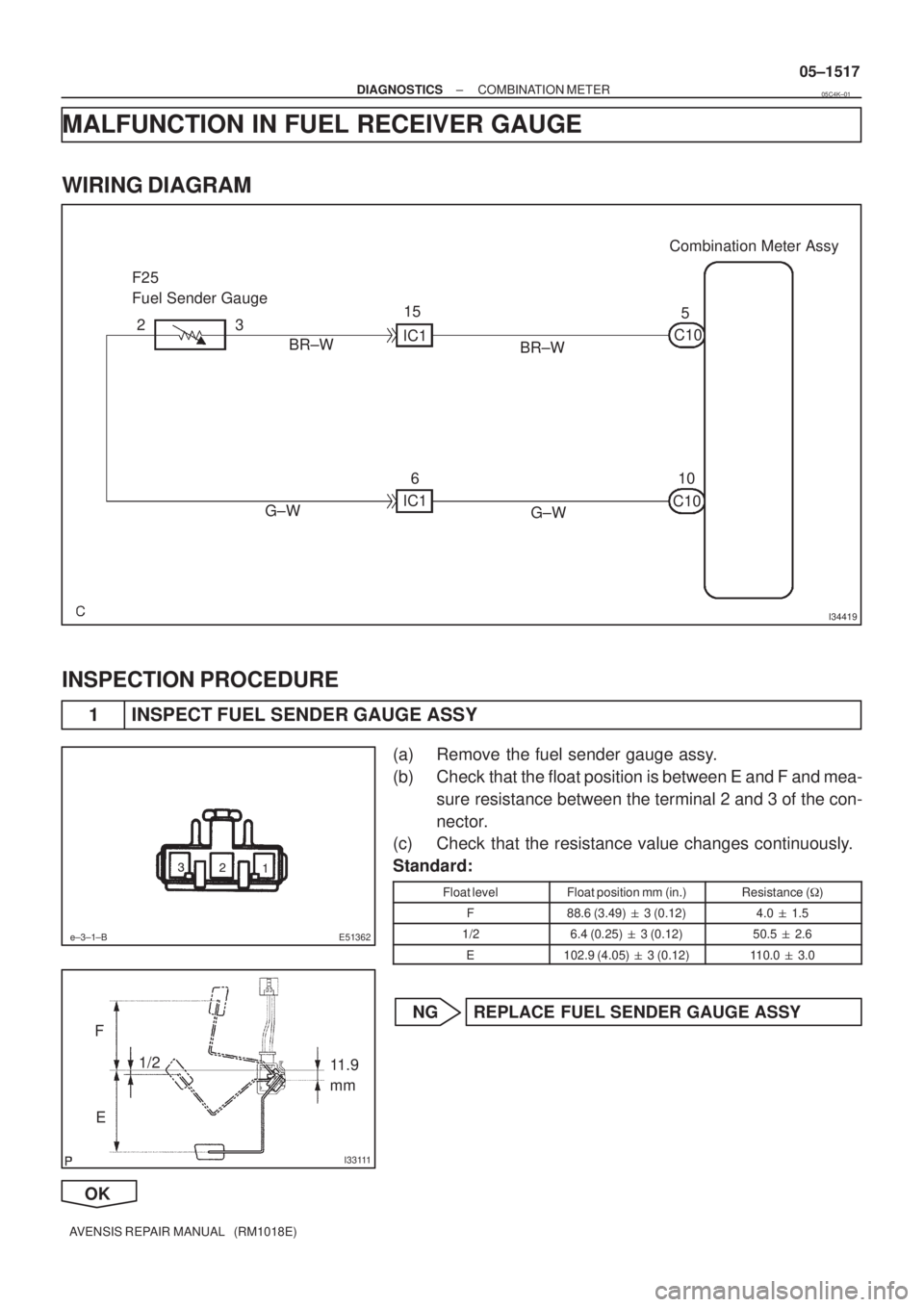
MALFUNCTION IN FUEL RECEIVER GAUGE
WIRING DIAGRAM
INSPECTION PROCEDURE
1 INSPECT FUEL SENDER GAUGE ASSY
(a) Remove the fuel sender gauge assy.
(b) Check that the float position is between E and F and mea-
sure resistance between the terminal 2 and 3 of the con-
nector.
(c) Check that the resistance value changes continuously.
Standard:
Float levelFloat position mm (in.)Resistance (�)
F88.6 (3.49) � 3 (0.12)4.0 � 1.5
1/26.4 (0.25) � 3 (0.12)50.5 � 2.6
E102.9 (4.05) � 3 (0.12)110.0 � 3.0
NG REPLACE FUEL SENDER GAUGE ASSY
OK
05C4K±01
Page 1581 of 5135
I34628
C10±5
C10±10
05±1518
± DIAGNOSTICSCOMBINATION METER
AVENSIS REPAIR MANUAL (RM1018E)
2 CHECK HARNESS AND CONNECTOR(BETWEEN FUEL SENDER GAUGE ASSY
AND COMBINATION METER)
(a) Remove the combination assy and fuel sender gauge.
(b) Check the continuity between the terminal 3 of the fuel
sender gauge and the terminal C10±5 of the combination
meter assy.
Standard: Continuity.
(c) Check continuity between the terminal 2 of the fuel send-
er gauge and the terminal C10±10 of the combination me-
ter assy.
Standard: Continuity.
NG REPAIR OR REPLACE HARNESS OR
CONNECTOR
OK
CHECK AND REPLACE COMBINATION METER ASSY
Page 1582 of 5135
 MPX1
(*2) (*3) E9
*1: 1AZ±FE
*2: 1AZ±FE, 1ZZ±FE, 3ZZ±FE
*3: 1CD±FTV
± DIAGNOSTICSCOMBINATION METER
05±1515
AVENSIS REPAIR MA")
������I35754
Combination Meter Assy ECM
13
C10
P 20
E9 18
E1023
(*1) MPX1
(*2) (*3) E9
*1: 1AZ±FE
*2: 1AZ±FE, 1ZZ±FE, 3ZZ±FE
*3: 1CD±FTV
± DIAGNOSTICSCOMBINATION METER
05±1515
AVENSIS REPAIR MANUAL (RM1018E)
MALFUNCTION IN WATER TEMPERATURE RECEIVER GAUGE
WIRING DIAGRAM
INSPECTION PROCEDURE
HINT:
The ECM sends information on the water temperature sensor to the meter through the Bean. If there is on
open or short circuit in the water temperature sensor circuit, the ECM outputs DTCs. Perform troubleshooting
with the ºEngine systemº.
1 READ VALUE OF HAND±HELD TESTER
(a) Operate the hand±held tester according to the steps on the display and select ºDATA LISTº.
ALL(ECM):
ItemMeasurement Item/
Range (Display)Normal ConditionDiagnostic Note
COOLANT TEMPCoolant Temperature / Min.:
±40�C, Max.: 140�CAfter warming up: 80 ± 95�C (176
± 203���If the value is º±40 �Cº or º140
�Cº, sensor circuit is open or
shorted.
NG GO TO ENGINE CONTROL SYSTEM
OK
2 CHECK THAT MALFUNCTION DISAPPEARS A KNOWN GOOD COMBINATION
METER IS INSTALLED
NG CHECK AND REPLACE ECM
OK
05C4J±01
Page 1583 of 5135
05±1516
± DIAGNOSTICSCOMBINATION METER
AVENSIS REPAIR MANUAL (RM1018E)
CHECK AND REPLACE COMBINATION METER ASSY
Page 1584 of 5135
I35753
TACHC11 Combination Meter Assy
E95 ECM
GR±R3
J27B
(*2) (*1) (*2) (*1)GR±R J9A
J26D
J8E
C115
W±B CK CA66
W±B W±B(*1)
W±B(*2) A
J15
J/C
IK IP ILCenter J/B
*1: LHD Models
*2: RHD Models J/C
± DIAGNOSTICSCOMBINATION METER
05±1513
AVENSIS REPAIR MANUAL (RM1018E)
MALFUNCTION IN TACHOMETER
WIRING DIAGRAM
INSPECTION PROCEDURE
1 READ VALUE OF HAND±HELD TESTER(ECM)
(a) Operate the hand±held tester according to the steps on the display and select ºDATE LISTº.
ALL(ECM):
ItemMeasurement Item/
Range (Display)Normal ConditionDiagnostic Note
ENGINE SPEEDEngine speed / Min.: 0 rpm, Max.:
16,383 rpmAlmost same at the meter rpm
(When engine is running)±
NG GO TO ENGINE CONTROL SYSTEM
OK
05C4I±01
Page 1585 of 5135
I34628
C11±5
C 11±3
���
A05138
05±1514
±
DIAGNOSTIC SCOMBIN ATIO N METER
A VENSIS RE PAIR MANUAL (RM1018E)
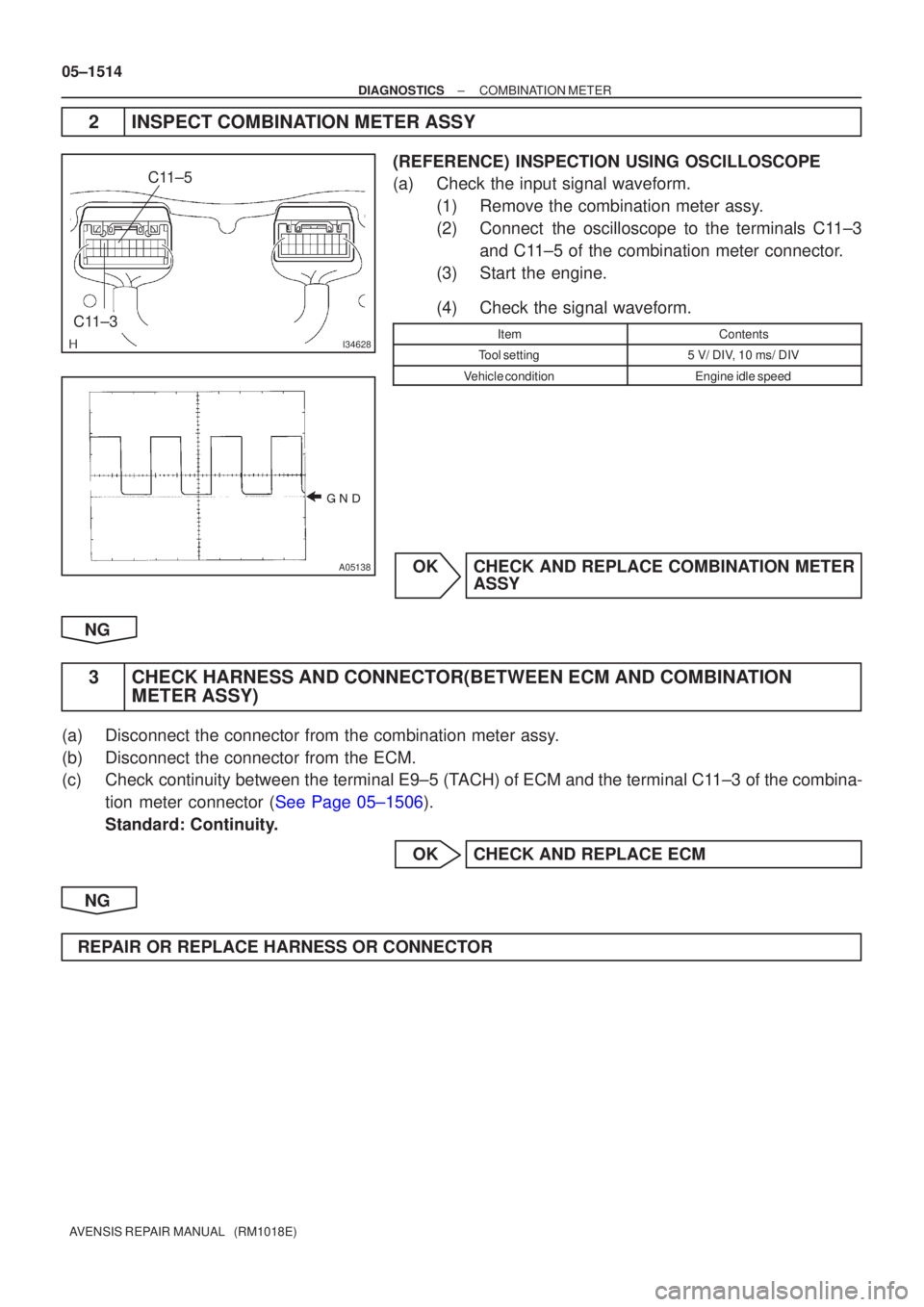
2 INSPEC T COMBIN ATION METER ASSY
(REFERENCE ) INSPECTION USING OSCILLOSCOPE
(a ) Check the input signal waveform.
(1 ) Remove the combination meter ass y.
(2 ) Connec t the oscilloscope to the terminals C 11±3
an d C 11±5 of the combination meter connecto r.
(3 ) Start the engine.
(4 ) Check the signal waveform.
ItemContents
Too l setting5 V/ DI V, 10 ms/ DIV
V ehicle conditionEngine idle speed
O K CHECK AND REPLACE COMBIN ATION METER
ASSY
NG
3 CHECK HARNESS AND CONNEC TOR(BETWEEN ECM AND COMBIN ATION
METER ASSY)
(a ) Disconnect the connector from the combination meter ass y.
(b ) Disconnect the connector from the ECM.
(c ) Chec k continuity between the terminal E9±5 ( TACH) of ECM and the terminal C 11± 3 of the combina-
tio n meter connector ( See Page 05±1506 ).
Standard: Continuity.
OK CHECK AND REPLACE ECM
NG
REPAIR OR REPLACE HARNESS OR CONNECTOR


INSPECTION PROCEDURE
1 INSPECT FUSE(GAUGE2, ECU±B)
(a) Check continuity in the GAUGE, D")

2 CHECK HARNESS AND CONNECTOR(BETWEEN FUEL SENDER GAUGE ASSY
AND COMBINATION METER)
(a) Remove the comb")

CHECK AND REPLACE COMBINATION METER ASSY")
 (*1) (*2) (*1)GR±R J9A
J26D
J8E
C115
W±B CK CA66
W±B W±B(*1)
W±B(*2) A
J15
J/C
IK IP ILCenter J/B
*1: LHD Models
*2: RHD Models J/C")