Page 1554 of 5135

INSPECTION PROCEDURE
1 CHECK SETTING(THE VOLUME")
I35667
AUI+
AUI±
FL± FL+
FR±FR+
Navigation ECU:
Radio Receiver Assy:
N3
R4
05±1480
± DIAGNOSTICSNAVIGATION SYSTEM
AVENSIS REPAIR MANUAL (RM1018E)
INSPECTION PROCEDURE
1 CHECK SETTING(THE VOLUME OF THE NAVIGATION VOICE SOUND)
(a) Check the settings.
(1) Set the volume MAX at the voice sound settings on the menu.
Standard: ºThis system will guide you in this volumeº is produced.
OK Go to step 4
NG
2 CHECK HARNESS AND CONNECTOR(NAVIGATION ECU ± RADIO RECEIVER
ASSY)
(a) Disconnect the connector between the navigation ECU
and radio receiver assy.
(1) Check continuity between the terminals at each
condition, as shown in the chart.
Standard:
Tester connectionSpecified condition
FL+*1, FR+*2 ± AUI+Continuity
FL±*1, FR±*2 ± AUI±Continuity
*1: LHD Models
*2: RHD Models
(2) Check for a short between the terminals at each
condition, as shown in the chart.
Standard:
Tester connectionSpecified condition
AUI+ ± Body groundNo continuity
AUI± ± Body groundNo continuity
NG REPAIR OR REPLACE HARNESS OR
CONNECTOR
OK
Page 1555 of 5135
I35668
FL+FR+
FR±FL±
R4
±
DIAGNOSTICS NAVIGATION SYSTEM
05±1481
AVENSIS REPAIR MANUAL (RM1018E)
3INSPECT RADIO RECEIVER ASSY(FL+(*1), FL±(*1), FR+(*2), FR±(*2), \
GND)
(a)Remove the radio receiver assy.
(b)Using an oscilloscope, check the signal waveform be-
tween the terminals FL+*
1, FL±*1, FR+*2, FR±*2 and GND
of stereo component amplifier assy.
*1: LHD Models
*2: RHD Models
Standard:
Tester connectionConditionSpecified condition
FL+*1, FR+*2 ± GNDWhile voice sound is being producedA waveform synchronized with sound is output
FL±*1, FL±*2 ±GNDWhile voice sound is being producedA waveform synchronized with sound is output
NGREPLACE RADIO RECEIVER ASSY (See page 67±5)
OK
4 INSPECT FRONT NO.1 SPEAKER ASSY
(a) Resistance check (1) Check resistance between the terminals of the front No.1 speaker assy.
Standard: 4 �
NOTICE:
The speaker should not be removed for checking
NG REPLACE FRONT NO.1 SPEAKER ASSY (See page 67±10)
OK
Page 1556 of 5135
I33631
Navigation ECU:
Front No. 1 Speaker Assy LH:AUO+
AUO±
N3
Front No. 1 Speaker Assy RH:
F21
F22
05±1482
±
DIAGNOSTICS NAVIGATION SYSTEM
AVENSIS REPAIR MANUAL (RM1018E)
5CHECK HARNESS AND CONNECTOR(NAVIGATION ECU ± FRONT NO. 1 SPEAKER ASSY)
(a)Disconnect the connectors from the navigation ECU and
front No.1 speaker assy.
(1)Check continuity between the terminals at eachcondition, as shown in the chart.
Standard:
Tester connectionSpecified condition
AUO+ ± 1Continuity
AUO± ± 2Continuity
(2)Check for a short between the terminals at each condition, as shown in the chart.
Standard:
Tester connectionSpecified condition
AUO+ ± Body groundNo continuity
AUO± ± Body groundNo continuity
NGREPAIR OR REPLACE HARNESS OR CONNECTOR
OK
REPLACE NAVIGATION ECU (See page 67±27)
Page 1557 of 5135
05C88±01
�����
�����
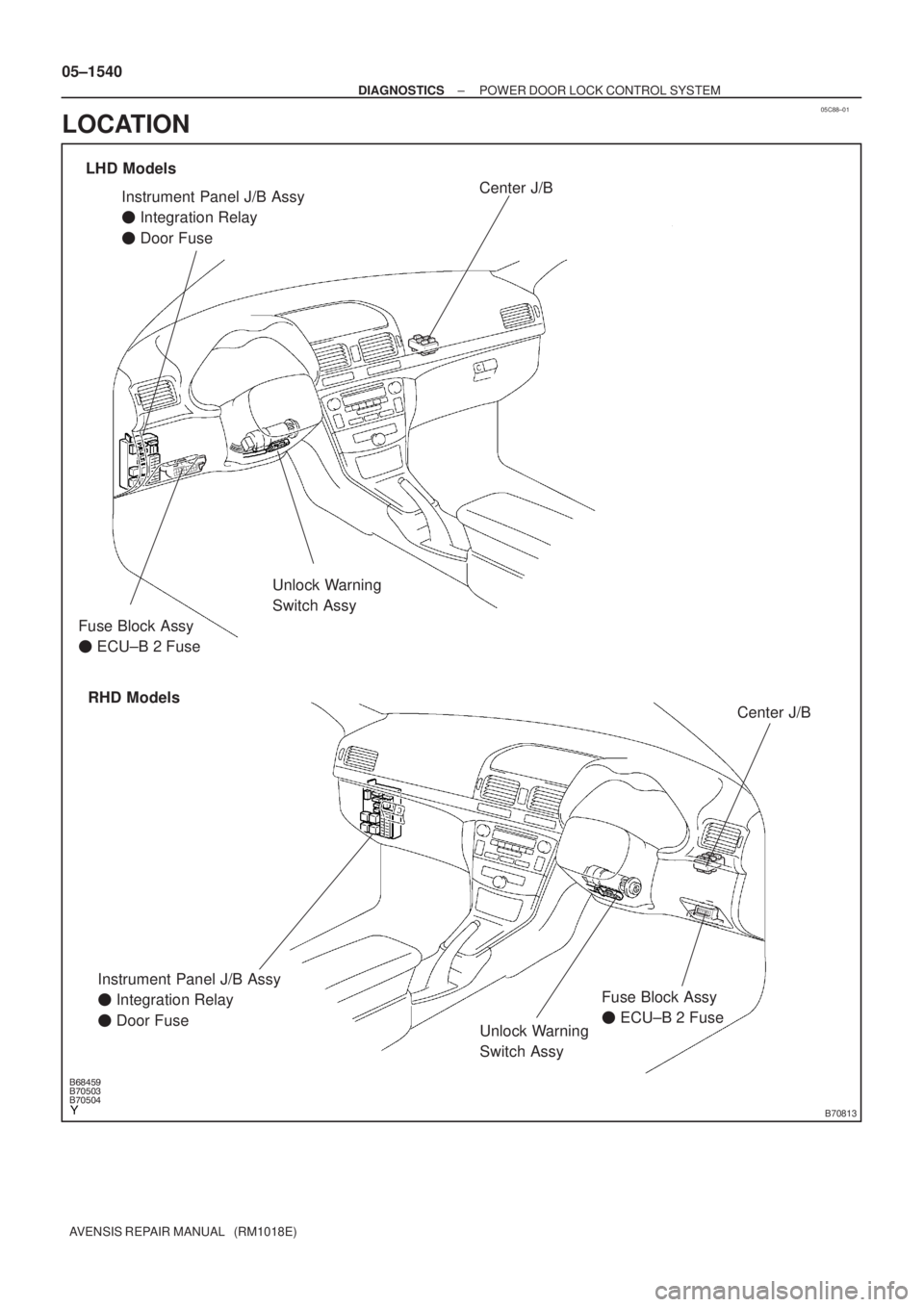
�����B70813
Unlock Warning
Switch Assy
Instrument Panel J/B Assy
� Integration Relay
� Door Fuse
Unlock Warning
Switch Assy
LHD Models
RHD ModelsCenter J/B
Center J/B
Fuse Block Assy
� ECU±B 2 Fuse
Instrument Panel J/B Assy
� Integration Relay
� Door FuseFuse Block Assy
� ECU±B 2 Fuse 05±1540
± DIAGNOSTICSPOWER DOOR LOCK CONTROL SYSTEM
AVENSIS REPAIR MANUAL (RM1018E)
LOCATION
Page 1558 of 5135
B70496
Front Door w/ Motor
Lock Assy LH
Front Door Courtesy
Lamp Switch Assy
Rear Door w/ Motor
Lock Assy LH
Rear Door Courtesy
Lamp Switch AssyFront Door Courtesy
Lamp Switch Assy
Rear Door w/ Motor
Lock Assy RH
Rear Door Courtesy
Lamp Switch Assy Front Door w/ Motor
Lock Assy RH
Sedan Models
Wagon Models Liftback Models
Back Door Lock Assy Power Window Regulator Master Switch Assy
� Door Control SwitchBack Door Lock Assy
Back Door Opener Switch Assy
(Outside Handle Switch)
Back Door Lock Assy
Back Door Opener Switch Assy
(Outside Handle Switch)Back Door Opener Switch Assy
(Outside Handle Switch)
± DIAGNOSTICSPOWER DOOR LOCK CONTROL SYSTEM
05±1541
AVENSIS REPAIR MANUAL (RM1018E)
Page 1559 of 5135
05C87±01
± DIAGNOSTICSPOWER DOOR LOCK CONTROL SYSTEM
05±1539
AVENSIS REPAIR MANUAL (RM1018E)
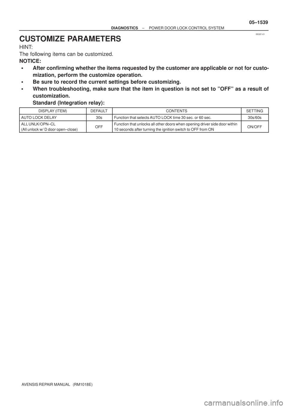
CUSTOMIZE PARAMETERS
HINT:
The following items can be customized.
NOTICE:
�After confirming whether the items requested by the customer are applicable or not for custo-
mization, perform the customize operation.
�Be sure to record the current settings before customizing.
�When troubleshooting, make sure that the item in question is not set to ºOFFº as a result of
customization.
Standard (Integration relay):
DISPLAY (ITEM)DEFAULTCONTENTSSETTING
AUTO LOCK DELAY30sFunction that selects AUTO LOCK time 30 sec. or 60 sec.30s/60s
ALL UNLK/OPN±CL
(All unlock w/ D door open±close)OFFFunction that unlocks all other doors when opening driver side door within
10 seconds after turning the ignition switch to OFF from ONON/OFF
Page 1560 of 5135

PRE±CHECK
1. DIAGNOSIS SYSTEM
(a)")
05C86±01
B50154
12 345 67 8
9 11121314 151610
DLC3
A82518
Hand±held Tester
05±1536
± DIAGNOSTICSPOWER DOOR LOCK CONTROL SYSTEM
AVENSIS REPAIR MANUAL (RM1018E)
PRE±CHECK
1. DIAGNOSIS SYSTEM
(a) Inspect the DLC3.
HINT:
The vehicle's ECM uses the ISO 14230 (M±OBD) communica-
tion protocol. The terminal arrangement of DLC3 complies with
ISO 15031±03 and matches the ISO 14230 format.
Tester ConnectionConditionSpecified Condition
7 (Bus + line) ± 5 (Signal ground)During communicationPulse generation
4 (Chassis ground) ± Body groundConstantBelow 1 �
5 (Signal ground) ± Body groundConstantBelow 1 �
16 (B+) ± Body groundConstant9 to 14 V
HINT:
If the display shows UNABLE TO CONNECT TO VEHICLE when you have connected the cable of the hand±
held tester to the DLC3, turned the ignition switch ON and used the hand±held tester, there is a problem on
the vehicle side or tester side.
�If communication is normal when the tester is connected to another vehicle, inspect the DLC3 of the
original vehicle.
�If communication is still impossible when the tester is connected to another vehicle, the problem is
probably in the tester itself, so consult the Service Department listed in the tester's manual.
(b) Check the battery voltage.
Battery voltage: 11 to 14 V
If voltage is below 11V, recharge the battery before proceeding.
2. USING HAND±HELD TESTER
(a) Connect the hand±held tester to the DLC3.
(b) Monitor the ECU data by following the prompts on the tes-
ter screen.
HINT:
The hand±held tester has a ºSnapshotº function which records
the monitored data.
Refer to the hand±held tester operator's manual for further de-
tails.
Page 1561 of 5135

3. DATA LIST
HINT:
According to the DATA LIST displayed by the hand±held tester, you can read the value of the")
± DIAGNOSTICSPOWER DOOR LOCK CONTROL SYSTEM
05±1537
AVENSIS REPAIR MANUAL (RM1018E)
3. DATA LIST
HINT:
According to the DATA LIST displayed by the hand±held tester, you can read the value of the switch, sensor,
actuator, etc. without parts removal. Reading the DATA LIST as the first step of troubleshooting is one way
to shorten the labor time.
(a) Connect the hand±held tester to the DLC3.
(b) Turn the ignition switch ON.
(c) Read the DATA LIST according to the display on the tester.
Standard (Integration relay):
ItemMeasurement Item/Display
(Range)Normal ConditionDiagnostic
Note
KEY UNLK WRN SWUnlock warning switch signal
/ON or OFFON: Key is in ignition key cylinder
OFF: No key is in ignition key cylinder±
D DOR CTY SW
Driver side door courtesy switch
signal
/ON or OFFON: Driver side door is open
OFF: Driver side door is closed±
P DOR CYT SW
Passenger side door courtesy
switch signal
/ON or OFFON: Passenger side door is open
OFF: Passenger side door is closed±
Rr DOR CTY SWRear door courtesy switch signal
/ON or OFFON: Either right or left rear door is open
OFF: Both right and left rear doors are closed±
P LOCK POS SW
Passenger side door lock position
switch signal
/ON or OFFON: Passenger side door lock is in unlock position
OFF: Passenger side door lock is in lock position±
Rr LOCK POS SW
Rear door lock position switch sig-
nal
/ON or OFFON: Rear door lock is in unlock position
OFF: Rear door lock is in lock position±
IG SWIG switch signal
/ON or OFFON: Key is in ON or START position
OFF: Key is in OFF or ACC position±
D LOCK POS SW
Driver side door lock position
switch signal
/ON or OFFON: Driver side door lock is in unlock position
OFF: Driver side door lock is in lock position±
D/L SW±LOCK
Manual door lock switch LOCK
signal
/ON or OFFON: Manual door lock switch is in lock position
OFF: Manual door lock switch is in original position
(Common to driver side and passenger side model)
±
D/L SW±UNLOCK
Manual door lock switch UNLOCK
signal
/ON or OFFON: Manual door lock switch is in unlock position
OFF: Manual door lock switch is in original position
(Common to driver side and passenger side model)
±
DOR KEY SW±LOCK
Key operation door lock switch sig-
nal
/ON or OFFON: Key operation door lock switch is in lock position
OFF: Key operation door lock switch is in original position
(Common to driver side and passenger side model)
±
P DOR KEY SW±UL
Key operation passenger door un-
lock switch signal
/ON or OFFON: Passenger key operation door lock switch is in unlock position
OFF: Passenger key operation door lock switch is in neutral position±
D DOR KEY SW±UL
Key operation driver door unlock
switch signal
/ON or OFFON: Driver key operation door lock switch is in unlock position
OFF: Driver key operation door lock switch is in original position±
ALL UNLK/OPN±CL
Driver side door courtesy switch
signal
/ON or OFFON: All doors unlock when driver side door is opened
OFF: Other doors do not unlock when driver side door is opened±
OPEN DOOR WARNDoor courtesy switch signal
/ON or OFFON: Either door is open
OFF: All doors are closed±
AUTO LOCK DELAYDoor courtesy switch signal
/60s or 30s60s: Door auto locking time is 60 sec.
30s: Door auto locking time is 30 sec.±

3INSPECT RADIO RECEIVER ASSY(FL+(*1), FL±(*1), FR+(*2), FR±(*2), \
GND)
(a)Remove the radio rece")

5CHECK HARNESS AND CON")