Page 1586 of 5135
I35752
SP1 C11Combination Meter Assy
S135 Skid Control ECU
IE1
L±W
L±W19 16 w/ VSC:
C115
W±B CK CA66
W±B W±B(*1)
W±B(*2) A
J15
J/C
IK IP ILCenter J/B
*1: LHD Models
*2: RHD Models
I35752
SP1 C11Combination Meter Assy
S223 Skid Control ECU
IE1
L±W
L±W19 16 w/o VSC:
C115
W±B CK CA66
W±B W±B(*1)
W±B(*2) A
J15
J/C
IK IP ILCenter J/B
*1: LHD Models
*2: RHD Models 05±1510
± DIAGNOSTICSCOMBINATION METER
AVENSIS REPAIR MANUAL (RM1018E)
MALFUNCTION IN SPEEDOMETER
WIRING DIAGRAM
05C4H±01
Page 1587 of 5135

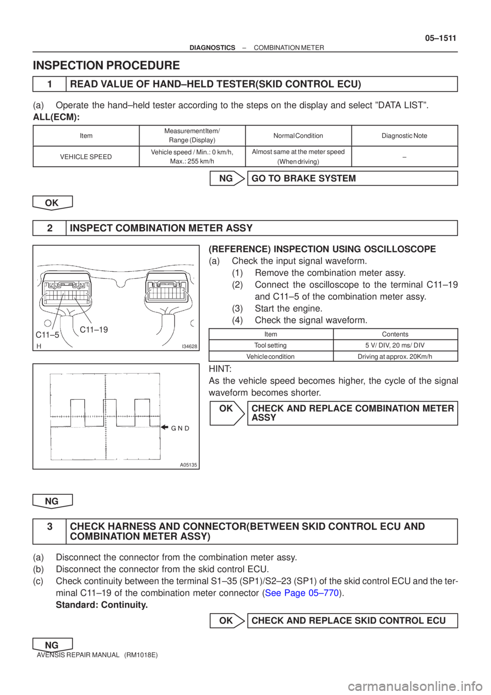
I34628
C11±19
C 11±5
���
A05135
±
DIAGNOSTIC SCOMBIN ATIO N METER
05±15 11
A VENSIS RE PAIR MANUAL (RM1018E)
INSPECTIO N PROCEDURE
1 READ V ALUE OF HAND±HELD TESTER(SKID CONTROL ECU)
(a ) Operat e the hand±held tester according to the steps on the display and selec\
t ºD ATA LISTº.
ALL(ECM):
ItemMeasuremen t Item/
Range (Display)Normal ConditionDiagnostic Note
VEHICLE SPEEDV ehicle speed / Min.: 0 km/h,
Max.: 255 km/hAlmost same at the meter speed
(When driving)±
NG GO T O BRAKE SYSTEM
OK
2 INSPECT COMBIN ATION METER ASSY
(REFERENCE) INSPECTION USING OSCILLOSCOPE
(a ) Check the input signal waveform.
(1 ) Remove the combination meter ass y.
(2 ) Connec t the oscilloscope to the terminal C 11±19
an d C 11±5 of the combination meter ass y.
(3 ) Start the engine.
(4 ) Check the signal waveform.
ItemContents
Too l setting5 V/ DI V, 20 ms/ DIV
V ehicle conditionDriving at approx. 20Km/h
HIN T:
A s the vehicle speed becomes highe r, the cycle of the signal
wavefor m becomes shorte r.
O K CHECK AND REPLACE COMBIN ATION METER
ASSY
NG
3 CHECK HARNESS AND CONNEC TOR(BETWEEN SKID CONTROL ECU AND
COMBIN ATION METER ASSY)
(a ) Disconnect the connector from the combination meter ass y.
(b ) Disconnect the connector from the skid control ECU.
(c ) Chec k continuity between the terminal S1±35 (SP1)/S2±23 (SP1) of th\
e skid control ECU and the ter-
mina l C 11±19 of the combination meter connector ( See Page 05±770 ).
Standard: Continuity.
OK CHECK AND REPLACE SKID CONTROL ECU
NG
Page 1588 of 5135
05±1512
± DIAGNOSTICSCOMBINATION METER
AVENSIS REPAIR MANUAL (RM1018E)
REPAIR OR REPLACE HARNESS OR CONNECTOR
Page 1589 of 5135
B66771
KSW
W±B8 U1
Unlock Warning Switch Assy
W±B
IP5
+B GROUND 1
W±R W±B
2
1Instrument Panel J/B Assy
PRG
RDA 16
2PRG
RDA D6
Door Control Receiver
7Integration
Relay
IC2 I14 3 G±Y
L±W 16
7
To
Battery
DA Y
IO*
1
6 8
Center
J/BIC2 G±Y
L±W
CA CD
AJ16
J/C LHD Models
19 I14
A W±B
IL*
2*1: Gasoline Engine
*2: 1CD±FTV
± DIAGNOSTICSWIRELESS DOOR LOCK CONTROL SYSTEM
05±1575
AVENSIS REPAIR MANUAL (RM1018E)
ONLY WIRELESS CONTROL FUNCTION DOES NOT OPERATE
(PREPARE NEW OR NORMAL TRANSMITTER OF THE SAME
TYPE VEHICLE)
CIRCUIT DESCRIPTION
The door control receiver receives a signal from the transmitter and sends this signal to the integration relay.
Then, the integration relay controls door operation by sending a door LOCK/UNLOCK signal and a luggage
door (back door) unlock signal to each door lock motor.
WIRING DIAGRAM
05BNB±01
Page 1590 of 5135
B66770
KSW
W±B8 U1
Unlock Warning Switch Assy
IP 5
+B GROUND 1
W±R W±B
2 1Instrument Panel J/B Assy
PRG
RDA 16
2PRG
RDA D6
Door Control Receiver
7Integration
Relay
IC2 I14 3
G±Y
L±W 16
7
To
Battery
DA Y*
2
IKIC2 G±Y
L±W
13 6
CF CA19 RHD Models
DJ22
J/C*
2
D
Center J/B
W±B Y*2
*1: 1AZ±FE
*
2: Except 1AZ±FEY*
1
A
J15
J/CI14 05±1576
± DIAGNOSTICSWIRELESS DOOR LOCK CONTROL SYSTEM
AVENSIS REPAIR MANUAL (RM1018E)
Page 1591 of 5135

±
DIAGNOSTICS WIRELESS DOOR LOCK CONTROL SYSTEM
05±1577
AVENSIS REPAIR MANUAL (RM1018E)
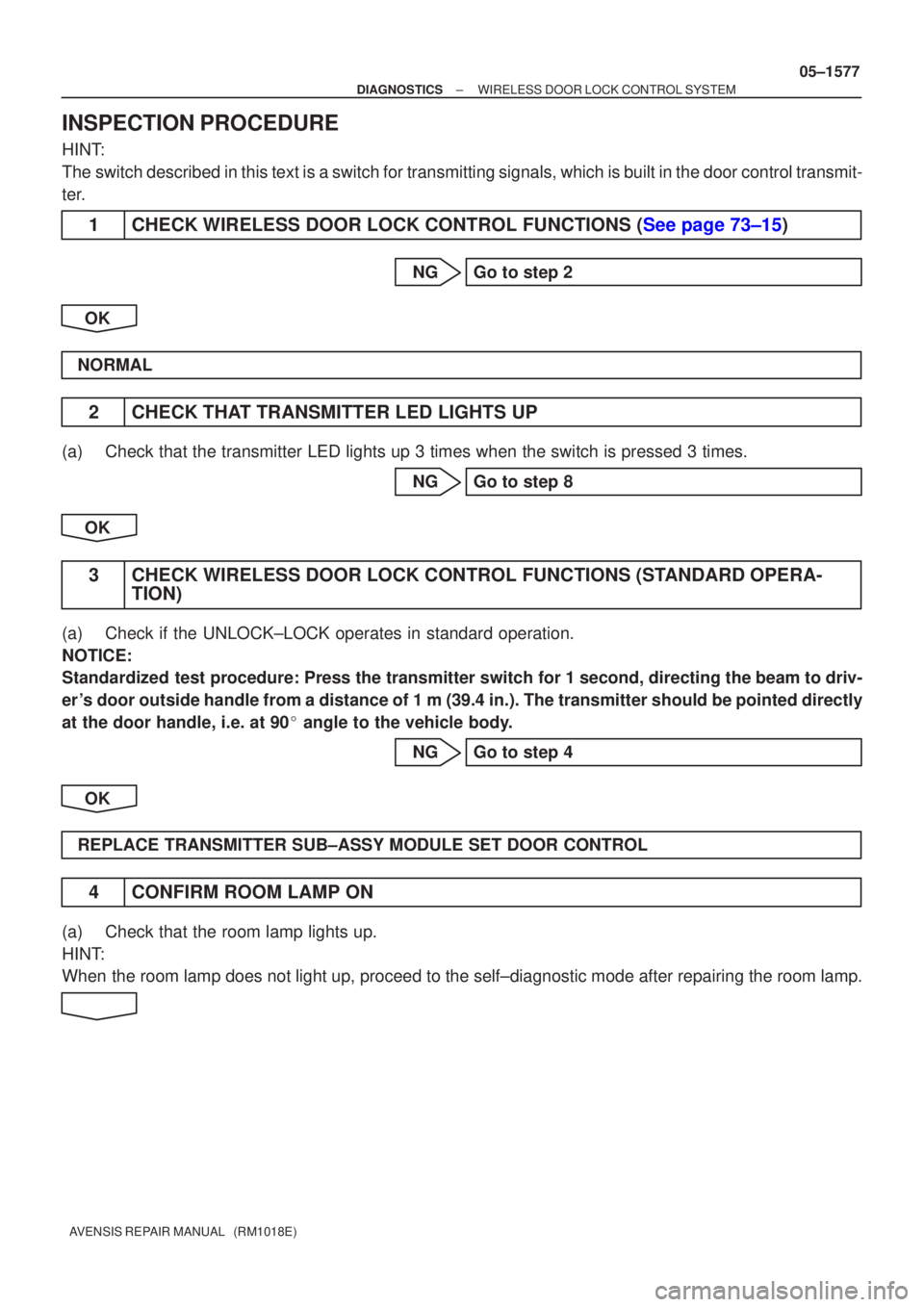
INSPECTION PROCEDURE
HINT:
The switch described in this text is a switch for transmitting signals, whi\
ch is built in the door control transmit-
ter.
1CHECK WIRELESS DOOR LOCK CONTROL FUNCTIONS (See page 73±15)
NG Go to step 2
OK
NORMAL
2 CHECK THAT TRANSMITTER LED LIGHTS UP
(a) Check that the transmitter LED lights up 3 times when the switch is pres\
sed 3 times. NG Go to step 8
OK
3 CHECK WIRELESS DOOR LOCK CONTROL FUNCTIONS (STANDARD OPERA- TION)
(a) Check if the UNLOCK±LOCK operates in standard operation.
NOTICE:
Standardized test procedure: Press the transmitter switch for 1 second, directing the beam to driv-
er 's door outside handle from a distance of 1 m (39.4 in.). The transmitte\
r should be pointed directly
at the door handle, i.e. at 90 � angle to the vehicle body.
NG Go to step 4
OK
REPLACE TRANSMITTER SUB±ASSY MODULE SET DOOR CONTROL
4 CONFIRM ROOM LAMP ON
(a) Check that the room lamp lights up.
HINT:
When the room lamp does not light up, proceed to the self±diagnostic mode\
after repairing the room lamp.
Page 1592 of 5135

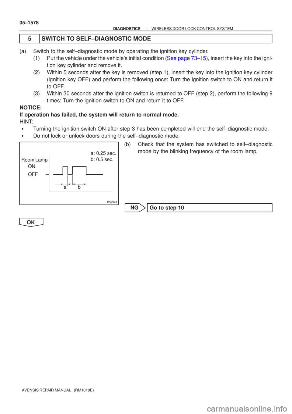
B52341
Room LampOFF a: 0.25 sec.
b: 0.5 sec.
ON
ab
05±1578
±
DIAGNOSTICS WIRELESS DOOR LOCK CONTROL SYSTEM
AVENSIS REPAIR MANUAL (RM1018E)
5 SWITCH TO SELF±DIAGNOSTIC MODE
(a) Switch to the self±diagnostic mode by operating the ignition key cylinder. (1)Put the vehicle under the vehicle's initial condition (See page 73±15), insert the key into the igni-
tion key cylinder and remove it.
(2) Within 5 seconds after the key is removed (step 1), insert the key int\
o the ignition key cylinder (ignition key OFF) and perform the following once: Turn the ignition switch to ON and return it
to OFF.
(3) Within 30 seconds after the ignition switch is returned to OFF (step 2)\
, perform the following 9
times: Turn the ignition switch to ON and return it to OFF.
NOTICE:
If operation has failed, the system will return to normal mode.
HINT:
�Turning the ignition switch ON after step 3 has been completed will end t\
he self±diagnostic mode.
�Do not lock or unlock doors during the self±diagnostic mode.
(b) Check that the system has switched to self±diagnosticmode by the blinking frequency of the room lamp.
NG Go to step 10
OK
Page 1593 of 5135

Room Lamp Output
Normal wave of UNLOCK switchUnmatching recognition code
No diagnosis outputs ON
OFF
T1: 0.25 sec. Wave is being received ON
OFF
OFF T1 T1 T1 T2 Normal wave of LOCK switch
ON
OFF
T1 T2
Normal wave of luggage door (back door)
unlock switch
ON
OFF
T2
T2
T2: 0.5 sec. Room Lamp Output
Room Lamp OutputRoom Lamp Output
Room Lamp Output
± DIAGNOSTICSWIRELESS DOOR LOCK CONTROL SYSTEM
05±1579
AVENSIS REPAIR MANUAL (RM1018E)
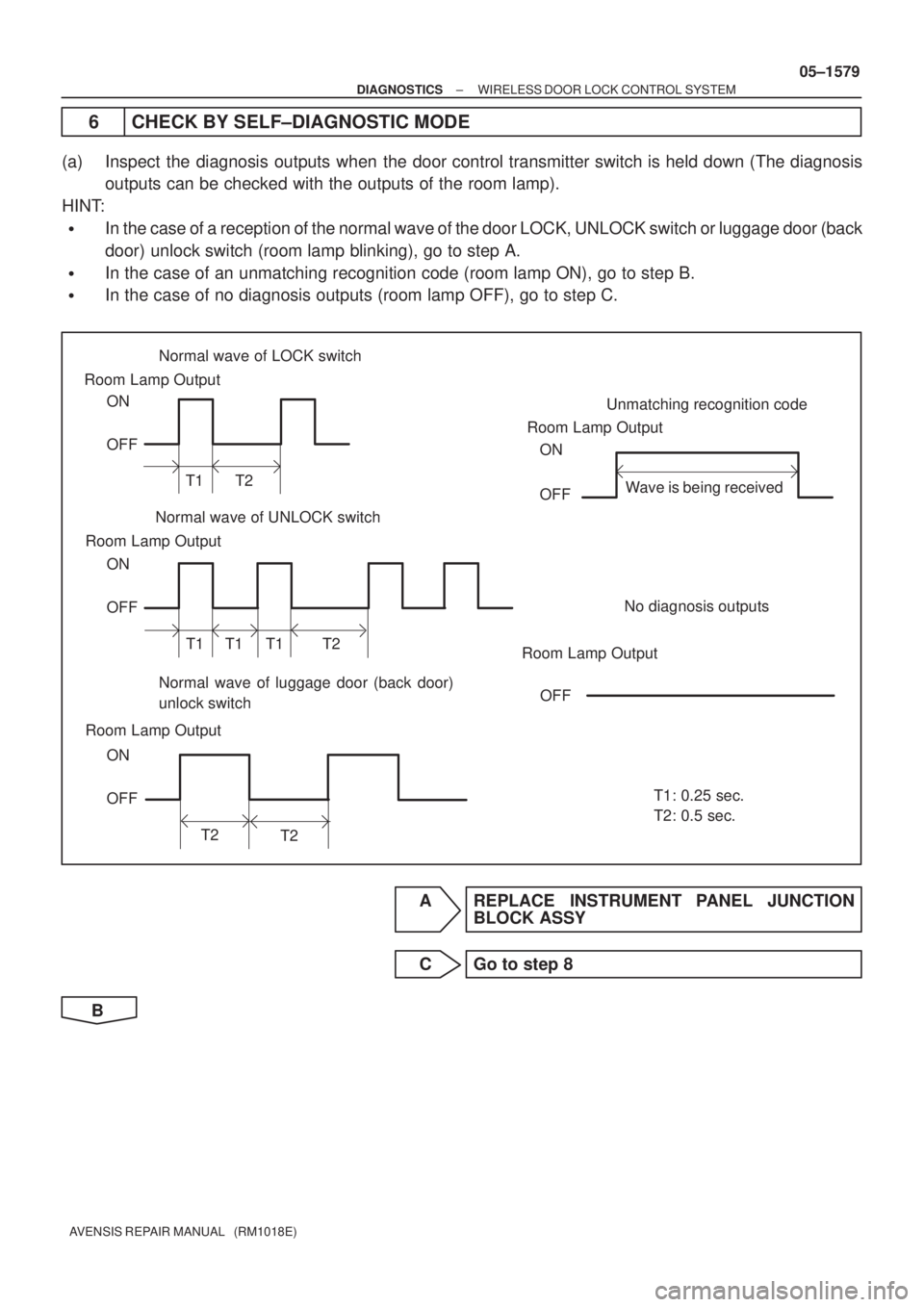
6 CHECK BY SELF±DIAGNOSTIC MODE
(a) Inspect the diagnosis outputs when the door control transmitter switch is held down (The diagnosis
outputs can be checked with the outputs of the room lamp).
HINT:
�In the case of a reception of the normal wave of the door LOCK, UNLOCK switch or luggage door (back
door) unlock switch (room lamp blinking), go to step A.
�In the case of an unmatching recognition code (room lamp ON), go to step B.
�In the case of no diagnosis outputs (room lamp OFF), go to step C.
A REPLACE INSTRUMENT PANEL JUNCTION
BLOCK ASSY
C Go to step 8
B