Page 1413 of 5135
�����
�\b���
�����
�����H42130
Curtain Shield
Squib RH Airbag
Sensor
Assy
Center
DLC3
CG TC DTC B1162/81
Floor Wire No.2
Service Wire
ICR+
ICR±
C
D
±
DIAGNOSTICS SUPPLEMENTAL RESTRAINT SYSTEM
05±1329
AVENSIS REPAIR MANUAL (RM1018E)
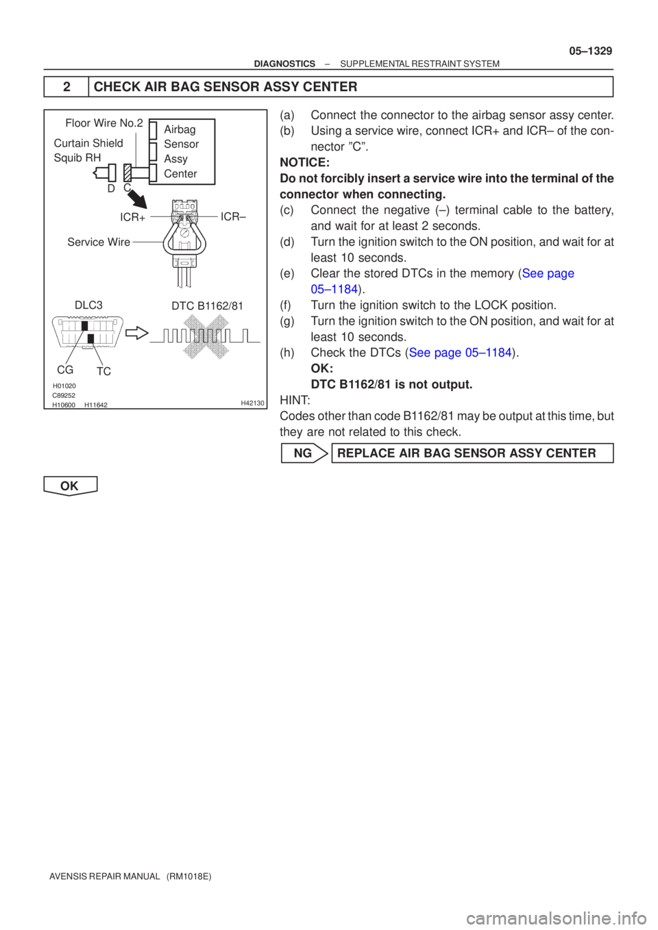
2 CHECK AIR BAG SENSOR ASSY CENTER
(a) Connect the connector to the airbag sensor assy center.
(b) Using a service wire, connect ICR+ and ICR± of the con-
nector ºCº.
NOTICE:
Do not forcibly insert a service wire into the terminal of the
connector when connecting.
(c) Connect the negative (±) terminal cable to the battery, and wait for at least 2 seconds.
(d) Turn the ignition switch to the ON position, and wait for at least 10 seconds.
(e)Clear the stored DTCs in the memory (See page
05±1184).
(f) Turn the ignition switch to the LOCK position.
(g) Turn the ignition switch to the ON position, and wait for at least 10 seconds.
(h)Check the DTCs (See page 05±1184).
OK:
DTC B1162/81 is not output.
HINT:
Codes other than code B1162/81 may be output at this time, but
they are not related to this check.
NG REPLACE AIR BAG SENSOR ASSY CENTER
OK
Page 1420 of 5135
0549I±12
I35610
1
6
DISC
SEEK UPSEEK DOWN
± DIAGNOSTICSAUDIO SYSTEM
05±1399
AVENSIS REPAIR MANUAL (RM1018E)
PRE±CHECK
1. DIAGNOSIS CHECK
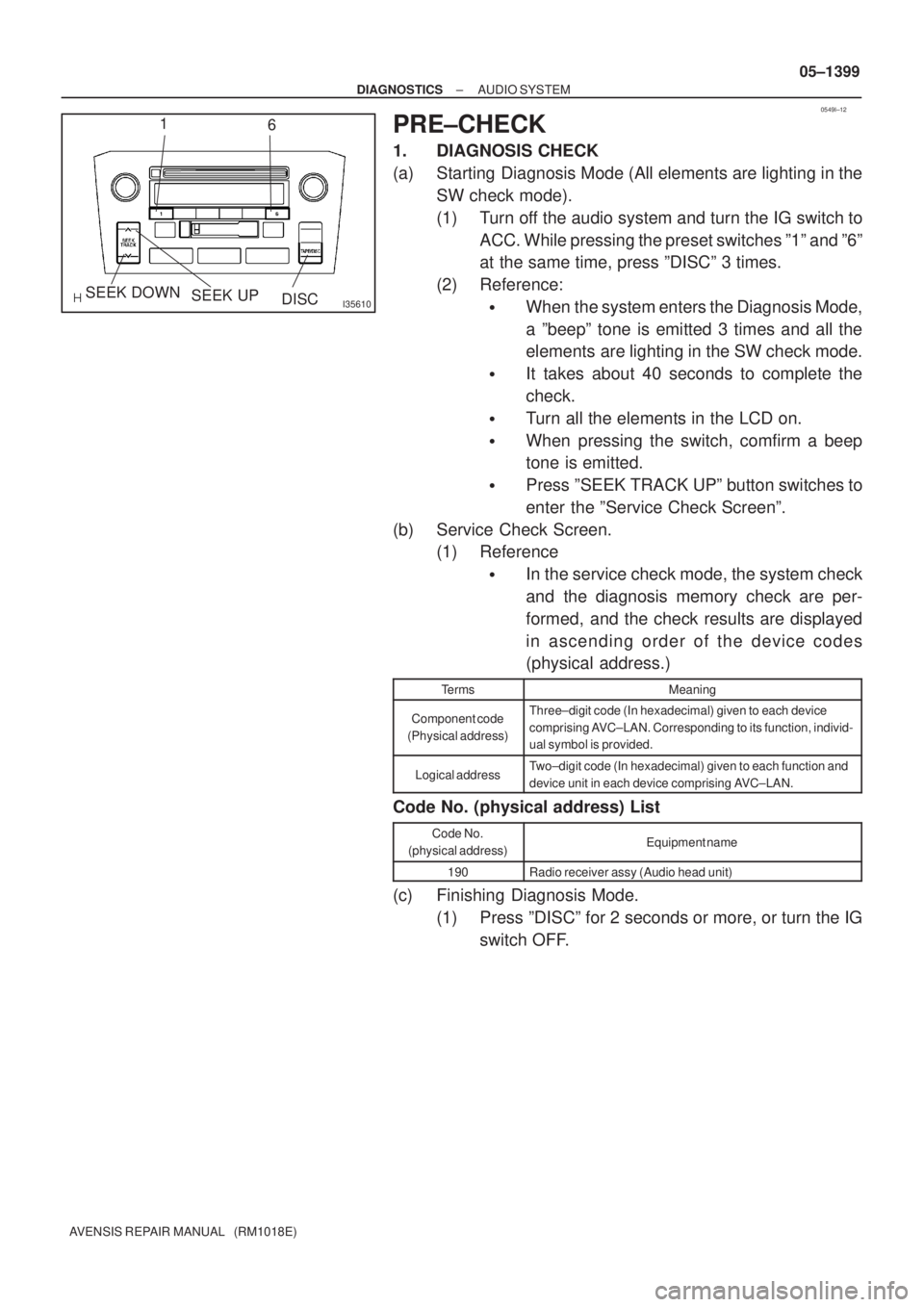
(a) Starting Diagnosis Mode (All elements are lighting in the
SW check mode).
(1) Turn off the audio system and turn the IG switch to
ACC. While pressing the preset switches º1º and º6º
at the same time, press ºDISCº 3 times.
(2) Reference:
�When the system enters the Diagnosis Mode,
a ºbeepº tone is emitted 3 times and all the
elements are lighting in the SW check mode.
�It takes about 40 seconds to complete the
check.
�Turn all the elements in the LCD on.
�When pressing the switch, comfirm a beep
tone is emitted.
�Press ºSEEK TRACK UPº button switches to
enter the ºService Check Screenº.
(b) Service Check Screen.
(1) Reference
�In the service check mode, the system check
and the diagnosis memory check are per-
formed, and the check results are displayed
in ascending order of the device codes
(physical address.)
TermsMeaning
Component code
(Physical address)Three±digit code (In hexadecimal) given to each device
comprising AVC±LAN. Corresponding to its function, individ-
ual symbol is provided.
Logical addressTwo±digit code (In hexadecimal) given to each function and
device unit in each device comprising AVC±LAN.
Code No. (physical address) List
Code No.
(physical address)Equipment name
190Radio receiver assy (Audio head unit)
(c) Finishing Diagnosis Mode.
(1) Press ºDISCº for 2 seconds or more, or turn the IG
switch OFF.
Page 1421 of 5135
05±1400
± DIAGNOSTICSAUDIO SYSTEM
AVENSIS REPAIR MANUAL (RM1018E)
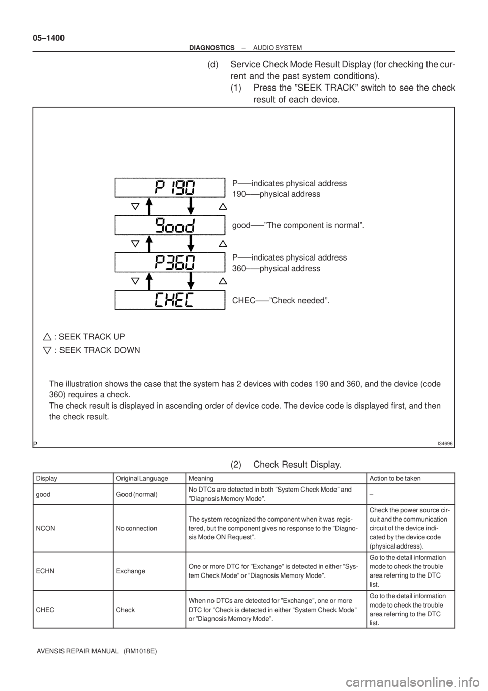
(d) Service Check Mode Result Display (for checking the cur-
rent and the past system conditions).
(1) Press the ºSEEK TRACKº switch to see the check
result of each device.
(2) Check Result Display.
DisplayOriginal LanguageMeaningAction to be taken
goodGood (normal)No DTCs are detected in both ºSystem Check Modeº and
ºDiagnosis Memory Modeº.±
NCONNo connection
The system recognized the component when it was regis-
tered, but the component gives no response to the ºDiagno-
sis Mode ON Requestº.
Check the power source cir-
cuit and the communication
circuit of the device indi-
cated by the device code
(physical address).
ECHNExchangeOne or more DTC for ºExchangeº is detected in either ºSys-
tem Check Modeº or ºDiagnosis Memory Modeº.
Go to the detail information
mode to check the trouble
area referring to the DTC
list.
CHECCheck
When no DTCs are detected for ºExchangeº, one or more
DTC for ºCheck is detected in either ºSystem Check Modeº
or ºDiagnosis Memory Modeº.Go to the detail information
mode to check the trouble
area referring to the DTC
list.
I34696
The illustration shows the case that the system has 2 devices with codes 190 and 360, and the device (code
360) requires a check.
The check result is displayed in ascending order of device code. The device code is displayed first, and then
the check result.P±±±indicates physical address
190±±±physical address
good±±±ºThe component is normalº.
P±±±indicates physical address
360±±±physical address
CHEC±±±ºCheck neededº.
: SEEK TRACK UP
: SEEK TRACK DOWN
Page 1422 of 5135
± DIAGNOSTICSAUDIO SYSTEM
05±1401
AVENSIS REPAIR MANUAL (RM1018E) DisplayAction to be taken Meaning Original Language
OLDOld versionOld DTC application is identified and DTC is detected in ei-
ther ºSystem Check Modeº or ºDiagnosis Memory Modeº.±
NRESNo response
The device gives no response to any one of ºSystem Check
Mode ON Requestº, ºSystem Check Result Requestº and
ºDiagnosis Memory Requestº.
Check the power source cir-
cuit and the communication
circuit of the device indi-
cated by the device code
(physical code).
(3) To perform the Service Check again, press the pre-
set switch º1º.
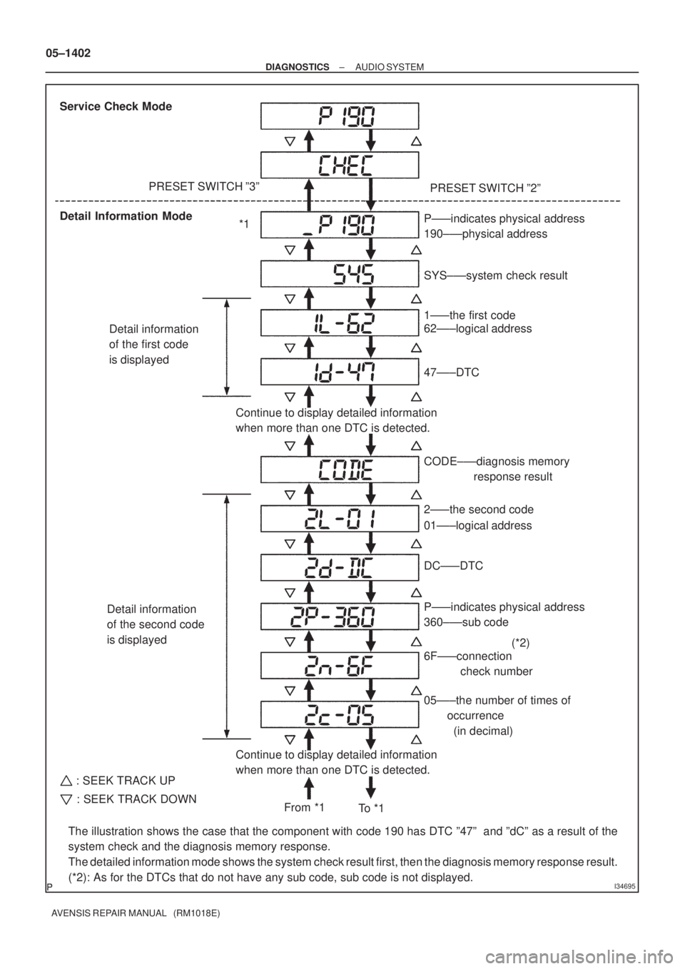
(e) Detailed information Mode (when displaying the troubled
device's DTC)
(1) With ºCHECº or ºECHNº being displayed, press the
preset switch º2º to go to the detailed information
mode.
(2) Press the ºSEEK TRACKº switch to display ºSystem
Check Result (SYS)º and ºDiagnosis Memory Re-
sponse (CODE)º.
Page 1423 of 5135
I34695
Service Check Mode
Detail Information ModePRESET SWITCH º3º
PRESET SWITCH º2º
Detail information
of the first code
is displayed
Detail information
of the second code
is displayed
Continue to display detailed information
when more than one DTC is detected.
The illustration shows the case that the component with code 190 has DTC º47º and ºdCº as a result of the
system check and the diagnosis memory response.
The detailed information mode shows the system check result first, then the diagnosis memory response result.
(*2): As for the DTCs that do not have any sub code, sub code is not displayed.P±±±indicates physical address
190±±±physical address
SYS±±±system check result
P±±±indicates physical address
360±±±sub code
6F±±±connection
check number 1±±±the first code
62±±±logical address
DC±±±DTC CODE±±±diagnosis memory
response result
2±±±the second code
01±±±logical address
05±±±the number of times of
occurrence
(in decimal) 47±±±DTC
Continue to display detailed information
when more than one DTC is detected.*1
From *1
To * 1(*2)
: SEEK TRACK UP
: SEEK TRACK DOWN
05±1402
± DIAGNOSTICSAUDIO SYSTEM
AVENSIS REPAIR MANUAL (RM1018E)
Page 1424 of 5135
± DIAGNOSTICSAUDIO SYSTEM
05±1403
AVENSIS REPAIR MANUAL (RM1018E)
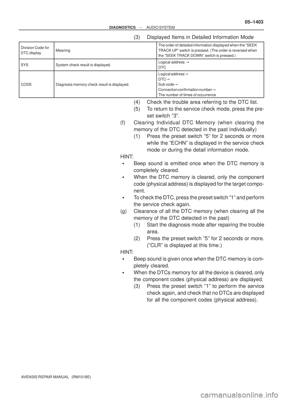
(3) Displayed Items in Detailed Information Mode
Division Code for
DTC displayMeaning
The order of detailed information displayed when the ºSEEK
TRACK UPº switch is pressed. (The order is reversed when
the ºSEEK TRACK DOWNº switch is pressed.)
SYSSystem check result is displayed.Logical address �
DTC
CODEDiagnosis memory check result is displayed.
Logical address�
DTC�
Sub code�
Connection confirmation number�
The number of times of occurrence
(4) Check the trouble area referring to the DTC list.
(5) To return to the service check mode, press the pre-
set switch º3º.
(f) Clearing Individual DTC Memory (when clearing the
memory of the DTC detected in the past individually)
(1) Press the preset switch º5º for 2 seconds or more
while the ºECHNº is displayed in the service check
mode or during the detail information mode.
HINT:
�Beep sound is emitted once when the DTC memory is
completely cleared.
�When the DTC memory is cleared, only the component
code (physical address) is displayed for the target compo-
nent.
�To check the DTC, press the preset switch º1º and perform
the service check again.
(g) Clearance of all the DTC memory (when clearing all the
memory of the DTC detected in the past)
(1) Start the diagnosis mode after repairing the trouble
area.
(2) Press the preset switch º5º for 2 seconds or more.
(ºCLRº is displayed at this time.)
HINT:
�Beep sound is given once when the DTC memory is com-
pletely cleared.
�When the DTCs memory for all the device is cleared, only
the component codes (physical address) are displayed.
(3) Press the preset switch º1º to perform the service
check again, and check that no DTCs are displayed
for all the component codes (physical address).
Page 1429 of 5135
0549F±10
30 kHz 300 kHz 3 MHz 30 MHz 300 MHz
LF MF HF VHF
AM FM
Frequency modulation Frequency
Designation
Radio wave
Modulation Amplitude modulation
BE2818
FM (Stereo)
FM (Monaural)
AM
BE2819
FadingIonosphere
± DIAGNOSTICSAUDIO SYSTEM
05±1393
AVENSIS REPAIR MANUAL (RM1018E)
AUDIO SYSTEM
DESCRIPTION
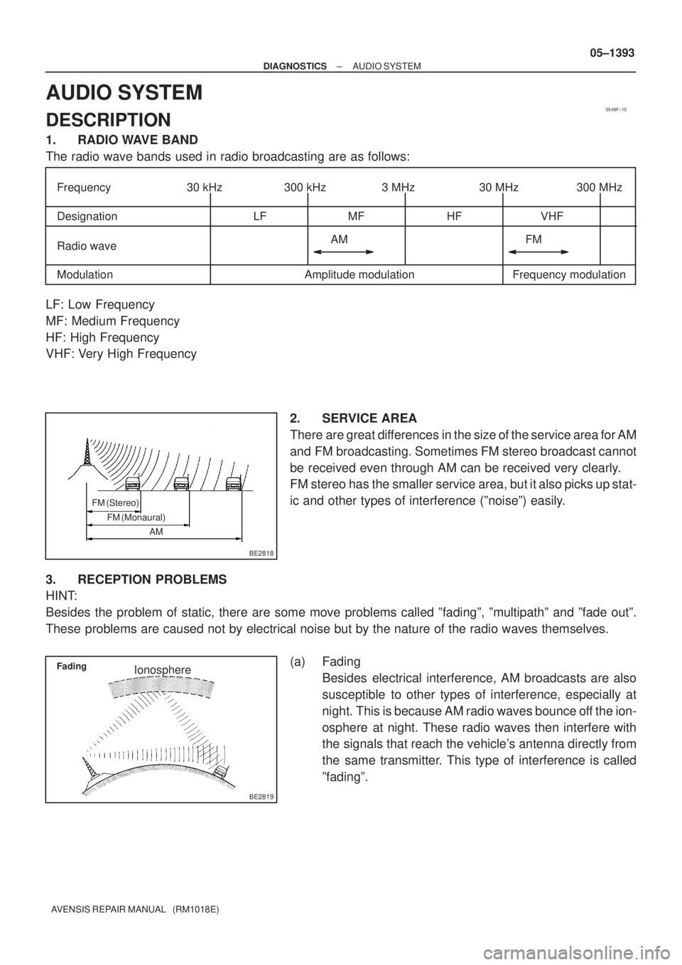
1. RADIO WAVE BAND
The radio wave bands used in radio broadcasting are as follows:
LF: Low Frequency
MF: Medium Frequency
HF: High Frequency
VHF: Very High Frequency
2. SERVICE AREA
There are great differences in the size of the service area for AM
and FM broadcasting. Sometimes FM stereo broadcast cannot
be received even through AM can be received very clearly.
FM stereo has the smaller service area, but it also picks up stat-
ic and other types of interference (ºnoiseº) easily.
3. RECEPTION PROBLEMS
HINT:
Besides the problem of static, there are some move problems called ºfadingº, ºmultipathº and ºfade outº.
These problems are caused not by electrical noise but by the nature of the radio waves themselves.
(a) Fading
Besides electrical interference, AM broadcasts are also
susceptible to other types of interference, especially at
night. This is because AM radio waves bounce off the ion-
osphere at night. These radio waves then interfere with
the signals that reach the vehicle's antenna directly from
the same transmitter. This type of interference is called
ºfadingº.
Page 1484 of 5135
± DIAGNOSTICSAUDIO SYSTEM
05±1411
AVENSIS REPAIR MANUAL (RM1018E)R11±8(SW2) ± R9±7(GND)
P ± BR*1
P ± W±B*2Steering pad switch is not operating
�MODE switch push4 or more �
Below 2.5
R12±9 (TX+)PSee ºService Check Modeº±
R12±10 (TX±)LGSee ºService Check Modeº±
*1: LHD
*2: RHD