Page 1490 of 5135
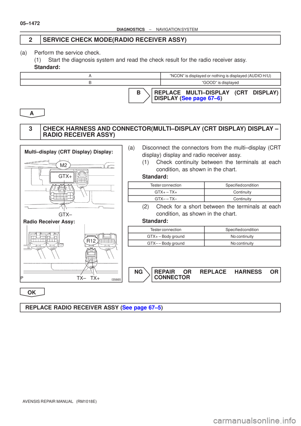
I35665
GTX+GTX±
TX+
TX±
Radio Receiver Assy: Multi±display (CRT Display) Display:
M2
R12
05±1472
±
DIAGNOSTICS NAVIGATION SYSTEM
AVENSIS REPAIR MANUAL (RM1018E)
2SERVICE CHECK MODE(RADIO RECEIVER ASSY)
(a)Perform the service check. (1)Start the diagnosis system and read the check result for the radio recei\
ver assy.
Standard:
AºNCONº is displayed or nothing is displayed (AUDIO H/U)
BºGOODº is displayed
BREPLACE MULTI±DISPLAY (CRT DISPLAY) DISPLAY (See page 67±6)
A
3CHECK HARNESS AND CONNECTOR(MULTI±DISPLAY (CRT DISPLAY) DISPLAY ± RADIO RECEIVER ASSY)
(a)Disconnect the connectors from the multi±display (CRT
display) display and radio receiver assy.
(1)Check continuity between the terminals at eachcondition, as shown in the chart.
Standard:
Tester connectionSpecified condition
GTX+ ± TX+Continuity
GTX± ± TX±Continuity
(2)Check for a short between the terminals at each condition, as shown in the chart.
Standard:
Tester connectionSpecified condition
GTX+ ± Body groundNo continuity
GTX± ± Body groundNo continuity
NGREPAIR OR REPLACE HARNESS OR CONNECTOR
OK
REPLACE RADIO RECEIVER ASSY (See page 67±5)
Page 1491 of 5135
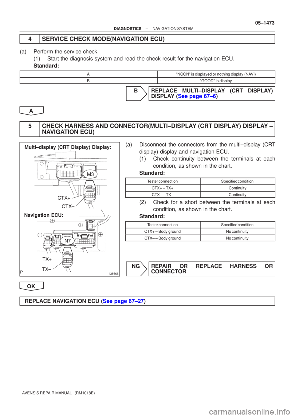
I35666
CTX+CTX±
TX+
TX±
Navigation ECU: Multi±display (CRT Display) Display:
M3
N7
±
DIAGNOSTICS NAVIGATION SYSTEM
05±1473
AVENSIS REPAIR MANUAL (RM1018E)
4SERVICE CHECK MODE(NAVIGATION ECU)
(a)Perform the service check.
(1)Start the diagnosis system and read the check result for the navigation \
ECU.
Standard:
AºNCONº is displayed or nothing display (NAVI)
BºGOODº is display
BREPLACE MULTI±DISPLAY (CRT DISPLAY) DISPLAY (See page 67±6)
A
5CHECK HARNESS AND CONNECTOR(MULTI±DISPLAY (CRT DISPLAY) DISPLAY ± NAVIGATION ECU)
(a)Disconnect the connectors from the multi±display (CRT
display) display and navigation ECU.
(1)Check continuity between the terminals at eachcondition, as shown in the chart.
Standard:
Tester connectionSpecified condition
CTX+ ± TX+Continuity
CTX± ± TX±Continuity
(2)Check for a short between the terminals at each condition, as shown in the chart.
Standard:
Tester connectionSpecified condition
CTX+ ± Body groundNo continuity
CTX± ± Body groundNo continuity
NGREPAIR OR REPLACE HARNESS OR CONNECTOR
OK
REPLACE NAVIGATION ECU (See page 67±27)
Page 1492 of 5135
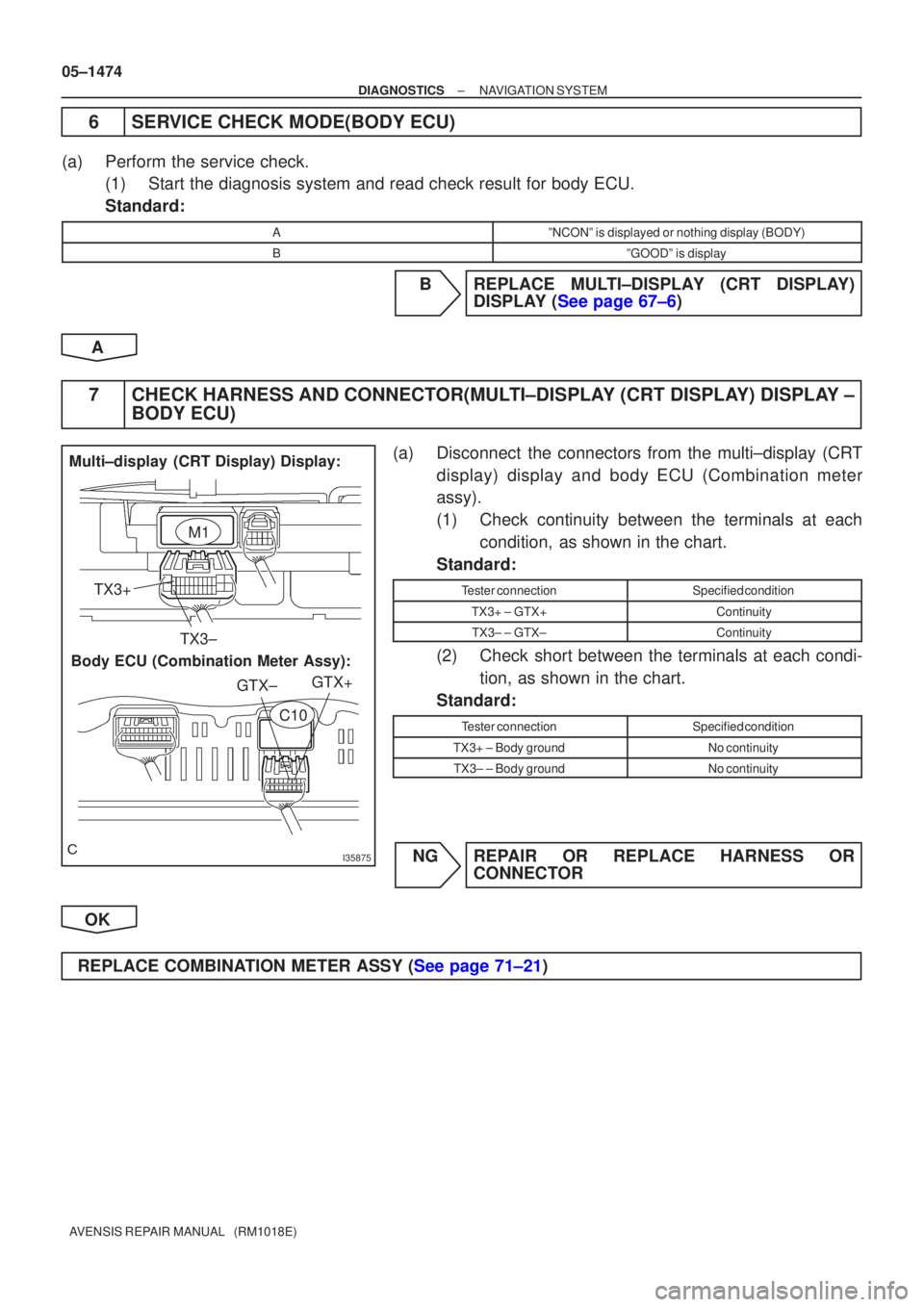
I35875
Multi±display (CRT Display) Display:Body ECU (Combination Meter Assy): TX3+
TX3± GTX+
GTX±
M1
C10
05±1474
±
DIAGNOSTICS NAVIGATION SYSTEM
AVENSIS REPAIR MANUAL (RM1018E)
6SERVICE CHECK MODE(BODY ECU)
(a)Perform the service check. (1)Start the diagnosis system and read check result for body ECU.
Standard:
AºNCONº is displayed or nothing display (BODY)
BºGOODº is display
BREPLACE MULTI±DISPLAY (CRT DISPLAY) DISPLAY (See page 67±6)
A
7CHECK HARNESS AND CONNECTOR(MULTI±DISPLAY (CRT DISPLAY) DISPLAY ± BODY ECU)
(a)Disconnect the connectors from the multi±display (CRT
display) display and body ECU (Combination meter
assy).
(1)Check continuity between the terminals at eachcondition, as shown in the chart.
Standard:
Tester connectionSpecified condition
TX3+ ± GTX+Continuity
TX3± ± GTX±Continuity
(2)Check short between the terminals at each condi- tion, as shown in the chart.
Standard:
Tester connectionSpecified condition
TX3+ ± Body groundNo continuity
TX3± ± Body groundNo continuity
NGREPAIR OR REPLACE HARNESS OR CONNECTOR
OK
REPLACE COMBINATION METER ASSY (See page 71±21)
Page 1500 of 5135
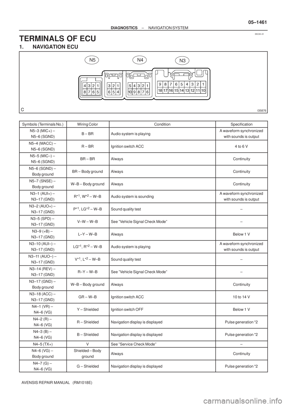
05C3X±01
I35876
N4N3N5
± DIAGNOSTICSNAVIGATION SYSTEM
05±1461
AVENSIS REPAIR MANUAL (RM1018E)
TERMINALS OF ECU
1. NAVIGATION ECU
Symbols (Terminals No.)Wiring ColorConditionSpecification
N5±3 (MIC+) ±
N5±6 (SGND)B ± BRAudio system is playingA waveform synchronized
with sounds is output
N5±4 (MACC) ±
N5±6 (SGND)R ± BRIgnition switch ACC4 to 6 V
N5±5 (MIC±) ±
N5±6 (SGND)BR ± BRAlwaysContinuity
N5±6 (SGND) ±
Body groundBR ± Body groundAlwaysContinuity
N5±7 (SNSE) ±
Body groundW±B ± Body groundAlwaysContinuity
N3±1 (AUI+) ±
N3±17 (GND)R*1, W*2 ± W±BAudio system is soundingA waveform synchronized
with sounds is output
N3±2 (AUO+) ±
N3±17 (GND)P*1, LG*2 ± W±BSound quality test±
N3±5 (SPD) ±
N3±17 (GND)V±W ± W±BSee ºVehicle Signal Check Modeº±
N3±9 (+B) ±
N3±17 (GND)L±Y ± W±BAlwaysBelow 1 V
N3±10 (AUI±) ±
N3±17 (GND)LG*1, R*2 ± W±BAudio system is playingA waveform synchronized
with sounds is output
N3±11 (AUO±) ±
N3±17 (GND)V*1, L*2 ± W±BSound quality test±
N3±14 (REV) ±
N3±17 (GND)R±Y ± W±BSee ºVehicle Signal Check Modeº±
N3±17 (GND) ±
Body groundW±B ± Body groundAlwaysContinuity
N3±18 (ACC) ±
N3±17 (GND)GR ± W±BIgnition switch ACC10 to 14 V
N4±1 (VR) ±
N4±6 (VG)Y ± ShieldedIgnition switch OFFBelow 1 V
N4±2 (R) ±
N4±6 (VG)R ± ShieldedNavigation display is displayedPulse generation *2
N4±3 (B) ±
N4±6 (VG)B ± ShieldedNavigation display is displayedPulse generation *2
N4±5 (TX+)VSee ºService Check Modeº±
N4±6 (VG) ±
Body groundShielded ± Body
groundAlwaysContinuity
N4±7 (G) ±
N4±6 (VG)G ± ShieldedNavigation display is displayedPulse generation *2
Page 1501 of 5135
I34717
M1M2M3 05±1462
± DIAGNOSTICSNAVIGATION SYSTEM
AVENSIS REPAIR MANUAL (RM1018E)Symbols (Terminals No.)Specification Condition Wiring Color
N4±8 (SYNC) ±
N4±6 (VG)W ± ShieldedNavigation display is displayedPulse generation *1
N4±10 (TX±)LGSee ºService Check Modeº±
*1: LHD
*2: RHD
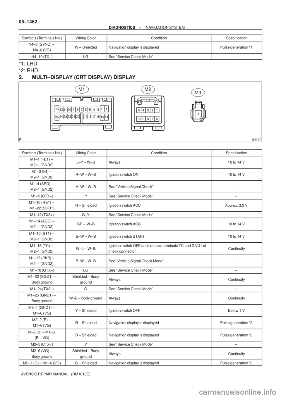
2. MULTI±DISPLAY (CRT DISPLAY) DISPLAY
Symbols (Terminals No.)Wiring ColorConditionSpecification
M1±1 (+B1) ±
M2±1 (GND2)L±Y ± W±BAlways10 to 14 V
M1±3 (IG) ±
M2±1 (GND2)R±W ± W±BIgnition switch ON10 to 14 V
M1±4 (SPD) ±
M2±1 (GND2)V±W ± W±BSee ºVehicle Signal Checkº±
M1±5 (GTX+)PSee ºService Check Modeº±
M1±10 (RE1) ±
M1±22 (SGD1)R ± ShieldedIgnition switch ACCApprox. 3.3 V
M1±12 (TX3+)G±YSee ºService Check Modeº±
M1±14 (ACC) ±
M2±1 (GND2)GR ± W±BIgnition switch ACC10 to 14 V
M1±15 (ST1) ±
M2±1 (GND2)B±W ± W±BIgnition switch START10 to 14 V
M1±16 (TC) ±
M2±1 (GND2)W±L ± W±BIgnition switch OFF and connect terminals TC and GND1 of
check connectorContinuity
M1±17 (PKB) ±
M2±1 (GND2)B±W ± W±BSee ºVehicle Signal Check Modeº±
M1±18 (GTX±)LGSee ºService Check Modeº±
M1±22 (SGD1) ±
Body groundShielded ± Body
groundAlwaysContinuity
M1±24 (TX3±)GSee ºService Check Modeº±
M1±25 (GND1) ±
Body groundW±B ± Body groundAlwaysContinuity
M2±1 (GND1) ±
M1±6 (VG)Y ± ShieldedIgnition switch OFFBelow 1 V
M2±2 (R) ±
M1±6 (VG)R ± ShieldedNavigation display is displayedPulse generation *2
M±2 (B) ± M1±6
(B ± VG)B ± ShieldedNavigation display is displayedPulse generation *2
M2±5 (CTX+)VSee ºService Check Modeº±
M2±6 (VG) ±
Body groundShielded ± Body
groundAlwaysContinuity
M2±7 (G) ± M1±6 (VG)G ± ShieldedNavigation display is displayedPulse generation *2
Page 1502 of 5135
I35656
C10
I30915
I30916
± DIAGNOSTICSNAVIGATION SYSTEM
05±1463
AVENSIS REPAIR MANUAL (RM1018E)Symbols (Terminals No.)Specification Condition Wiring Color
M2±8 (SYNC) ±
M1±6 (VG)W ± ShieldedNavigation display is displayedPulse generation *1
M2±10 (CTX±)LGSee ºService Check Modeº±
M3±1 (GND2) ±
Body groundW±B ± Body groundAlwaysContinuity
3. BODY ECU (COMBINATION METER ASSY)
Symbols (Terminals No.)Wiring ColorConditionSpecification
C10±3 (GTX+)G±YSee ºService Check Modeº±
C10±4 (GTX±)GSee ºService Check Modeº±
(a) *1: Oscilloscope wave
Terminal to be measured: SYNC ± GND
Setting for measurement: 500 mV/DIV10± �s/DIV
Condition: Navigation display is displayed.
(b) *2: Oscilloscope wave
Terminal to be measured: R, G, B ± GND
Setting for measurement: 200 mV/DIV10± �s/DIV
Condition: Navigation map is switched.
Page 1512 of 5135
I34691
Navigation system normal operation
Enter ºSERVICE CHECK MODEº (See section 5)
Enter ºNAVIGATION
CHECKº (See section 7)Diagnosis start±up (refer to next page)
HINT:
When Diagnosis System
mode starts, system
check is performed
at first and the check
result is displayed.
Enter ºDISPLAY CHECKº
(See section 6)
± DIAGNOSTICSNAVIGATION SYSTEM
05±1439
AVENSIS REPAIR MANUAL (RM1018E)
4. DIAGNOSIS SYSTEM MODE
Page 1513 of 5135
I34690
ºINFOº
Switch
Navigation Controller Assy:
I35902
05±1440
± DIAGNOSTICSNAVIGATION SYSTEM
AVENSIS REPAIR MANUAL (RM1018E)
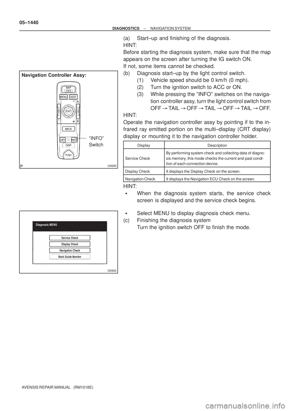
(a) Start±up and finishing of the diagnosis.
HINT:
Before starting the diagnosis system, make sure that the map
appears on the screen after turning the IG switch ON.
If not, some items cannot be checked.
(b) Diagnosis start±up by the light control switch.
(1) Vehicle speed should be 0 km/h (0 mph).
(2) Turn the ignition switch to ACC or ON.
(3) While pressing the ºINFOº switches on the naviga-
tion controller assy, turn the light control switch from
OFF � TAIL � OFF � TAIL � OFF � TAIL � OFF.
HINT:
Operate the navigation controller assy by pointing if to the in-
frared ray emitted portion on the multi±display (CRT display)
display or mounting it to the navigation controller holder.
DisplayDescription
Service Check
By performing system check and collecting data of diagno-
sis memory, this mode checks the current and past condi-
tion of each connection device.
Display CheckIt displays the Display Check on the screen.
Navigation CheckIt displays the Navigation ECU Check on the screen.
HINT:
�When the diagnosis system starts, the service check
screen is displayed and the service check begins.
�Select MENU to display diagnosis check menu.
(c) Finishing the diagnosis system
Turn the ignition switch OFF to finish the mode.