Page 1341 of 5135
�����
�����H43084
Airbag
Sensor
Assy
Center
Seat Position
Airbag Sensor
LSP+LSP±
Floor Wire
A
B C D
LSP+
LSP±
Service Wire
�����
�����H42231
Airbag
Sensor
Assy
Center
LSP+LSP±
Floor Wire
Seat Position
Airbag SensorA
B C D
05±1306
± DIAGNOSTICSSUPPLEMENTAL RESTRAINT SYSTEM
AVENSIS REPAIR MANUAL (RM1018E)
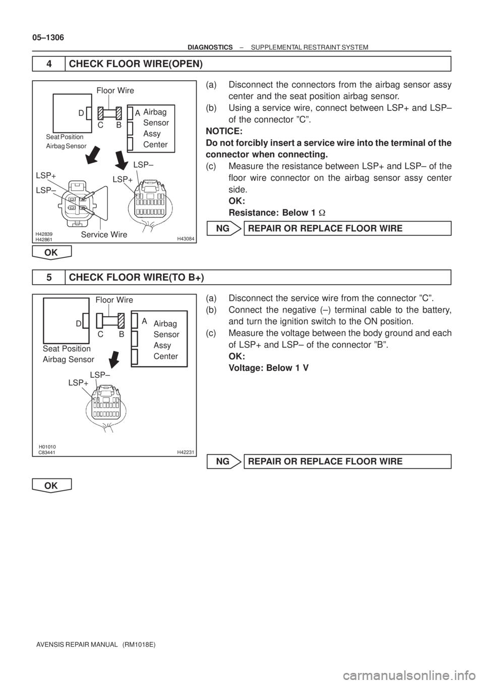
4 CHECK FLOOR WIRE(OPEN)
(a) Disconnect the connectors from the airbag sensor assy
center and the seat position airbag sensor.
(b) Using a service wire, connect between LSP+ and LSP±
of the connector ºCº.
NOTICE:
Do not forcibly insert a service wire into the terminal of the
connector when connecting.
(c) Measure the resistance between LSP+ and LSP± of the
floor wire connector on the airbag sensor assy center
side.
OK:
Resistance: Below 1 �
NG REPAIR OR REPLACE FLOOR WIRE
OK
5 CHECK FLOOR WIRE(TO B+)
(a) Disconnect the service wire from the connector ºCº.
(b) Connect the negative (±) terminal cable to the battery,
and turn the ignition switch to the ON position.
(c) Measure the voltage between the body ground and each
of LSP+ and LSP± of the connector ºBº.
OK:
Voltage: Below 1 V
NG REPAIR OR REPLACE FLOOR WIRE
OK
Page 1344 of 5135
����� �����H43089
Airbag
Sensor
Assy
Center Seat Position
Airbag Sensor
RSP±
RSP+
Floor Wire No. 2
A
B C D
RSP± RSP+
H41028
Airbag
Sensor
Assy
Center
Seat Position
Airbag SensorRSP±
RSP+Floor Wire No. 2
A
B C D
± DIAGNOSTICSSUPPLEMENTAL RESTRAINT SYSTEM
05±1309
AVENSIS REPAIR MANUAL (RM1018E)
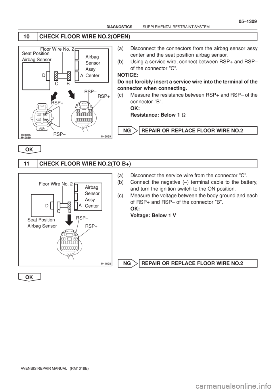
10 CHECK FLOOR WIRE NO.2(OPEN)
(a) Disconnect the connectors from the airbag sensor assy
center and the seat position airbag sensor.
(b) Using a service wire, connect between RSP+ and RSP±
of the connector ºCº.
NOTICE:
Do not forcibly insert a service wire into the terminal of the
connector when connecting.
(c) Measure the resistance between RSP+ and RSP± of the
connector ºBº.
OK:
Resistance: Below 1 �
NG REPAIR OR REPLACE FLOOR WIRE NO.2
OK
11 CHECK FLOOR WIRE NO.2(TO B+)
(a) Disconnect the service wire from the connector ºCº.
(b) Connect the negative (±) terminal cable to the battery,
and turn the ignition switch to the ON position.
(c) Measure the voltage between the body ground and each
of RSP+ and RSP± of the connector ºBº.
OK:
Voltage: Below 1 V
NG REPAIR OR REPLACE FLOOR WIRE NO.2
OK
Page 1349 of 5135
����� �����������H42523
Airbag
Sensor
Assy
Center
Airbag Sensor
Front LH
Service Wire
SL+
SL±A
B
C
D E F
�����������H42510
Airbag
Sensor
Assy
Center
Airbag Sensor
Front LH
SL+
SL±A
B C
D E F
05±1300
± DIAGNOSTICSSUPPLEMENTAL RESTRAINT SYSTEM
AVENSIS REPAIR MANUAL (RM1018E)
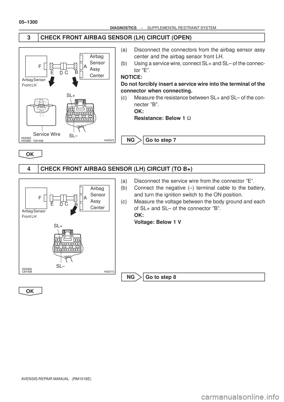
3 CHECK FRONT AIRBAG SENSOR (LH) CIRCUIT (OPEN)
(a) Disconnect the connectors from the airbag sensor assy
center and the airbag sensor front LH.
(b) Using a service wire, connect SL+ and SL± of the connec-
tor ºEº.
NOTICE:
Do not forcibly insert a service wire into the terminal of the
connector when connecting.
(c) Measure the resistance between SL+ and SL± of the con-
necter ºBº.
OK:
Resistance: Below 1 �
NG Go to step 7
OK
4 CHECK FRONT AIRBAG SENSOR (LH) CIRCUIT (TO B+)
(a) Disconnect the service wire from the connector ºEº.
(b) Connect the negative (±) terminal cable to the battery,
and turn the ignition switch to the ON position.
(c) Measure the voltage between the body ground and each
of SL+ and SL± of the connector ºBº.
OK:
Voltage: Below 1 V
NG Go to step 8
OK
Page 1351 of 5135
�����
����� �����H42524
Engine Room
Main Wire
SL± SL+
Service Wire
Airbag
Sensor
Assy
Center
Airbag Sensor
Front LH
A
B C
D E FInstrument Panel Wire
SL±
SL+
����� �����H42512
Engine Room
Main Wire
SL± SL+Airbag
Sensor
Assy
Center
Airbag Sensor
Front LH
A
B C
D E FInstrument Panel Wire
05±1302
± DIAGNOSTICSSUPPLEMENTAL RESTRAINT SYSTEM
AVENSIS REPAIR MANUAL (RM1018E)
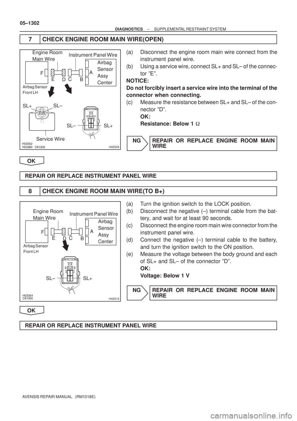
7 CHECK ENGINE ROOM MAIN WIRE(OPEN)
(a) Disconnect the engine room main wire connect from the
instrument panel wire.
(b) Using a service wire, connect SL+ and SL± of the connec-
tor ºEº.
NOTICE:
Do not forcibly insert a service wire into the terminal of the
connector when connecting.
(c) Measure the resistance between SL+ and SL± of the con-
nector ºDº.
OK:
Resistance: Below 1 �
NG REPAIR OR REPLACE ENGINE ROOM MAIN
WIRE
OK
REPAIR OR REPLACE INSTRUMENT PANEL WIRE
8 CHECK ENGINE ROOM MAIN WIRE(TO B+)
(a) Turn the ignition switch to the LOCK position.
(b) Disconnect the negative (±) terminal cable from the bat-
tery, and wait for at least 90 seconds.
(c) Disconnect the engine room main wire connector from the
instrument panel wire.
(d) Connect the negative (±) terminal cable to the battery,
and turn the ignition switch to the ON position.
(e) Measure the voltage between the body ground and each
of SL+ and SL± of the connector ºDº.
OK:
Voltage: Below 1 V
NG REPAIR OR REPLACE ENGINE ROOM MAIN
WIRE
OK
REPAIR OR REPLACE INSTRUMENT PANEL WIRE
Page 1355 of 5135
����� �����������H42523
Airbag
Sensor
Assy
CenterAirbag
Front
RH Sensor
Service Wire
SR+
SR±
A
B
C
D E F
�����������H42510
Airbag
Sensor
Assy
CenterAirbag
Front
RH Sensor
SR+
SR±
A
B
C
D E F
05±1294
± DIAGNOSTICSSUPPLEMENTAL RESTRAINT SYSTEM
AVENSIS REPAIR MANUAL (RM1018E)
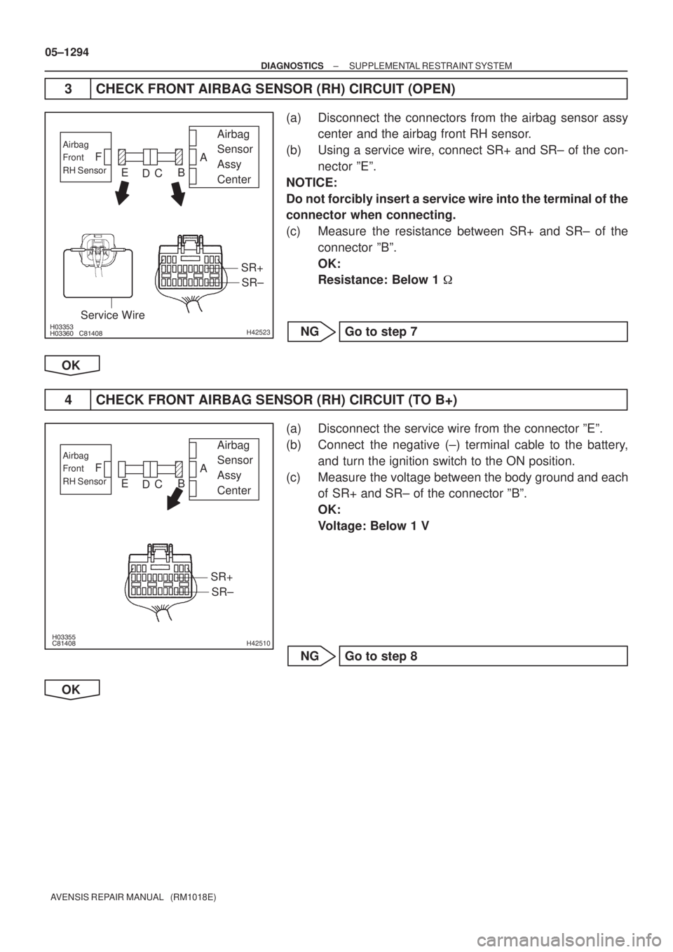
3 CHECK FRONT AIRBAG SENSOR (RH) CIRCUIT (OPEN)
(a) Disconnect the connectors from the airbag sensor assy
center and the airbag front RH sensor.
(b) Using a service wire, connect SR+ and SR± of the con-
nector ºEº.
NOTICE:
Do not forcibly insert a service wire into the terminal of the
connector when connecting.
(c) Measure the resistance between SR+ and SR± of the
connector ºBº.
OK:
Resistance: Below 1 �
NG Go to step 7
OK
4 CHECK FRONT AIRBAG SENSOR (RH) CIRCUIT (TO B+)
(a) Disconnect the service wire from the connector ºEº.
(b) Connect the negative (±) terminal cable to the battery,
and turn the ignition switch to the ON position.
(c) Measure the voltage between the body ground and each
of SR+ and SR± of the connector ºBº.
OK:
Voltage: Below 1 V
NG Go to step 8
OK
Page 1357 of 5135
�����
����� �����H42524
Engine Room
Main Wire
Airbag
Sensor
Assy
CenterAirbag
Front
RH
Sensor
Instrument Panel Wire
SR±SR+
Service Wire
A
B
C D E F
SR± SR+
����� �����H42512
Engine Room
Main Wire
Airbag
Sensor
Assy
CenterAirbag
Front
RH
Sensor
Instrument Panel Wire
SR±SR+
A
B
C D E F
05±1296
± DIAGNOSTICSSUPPLEMENTAL RESTRAINT SYSTEM
AVENSIS REPAIR MANUAL (RM1018E)
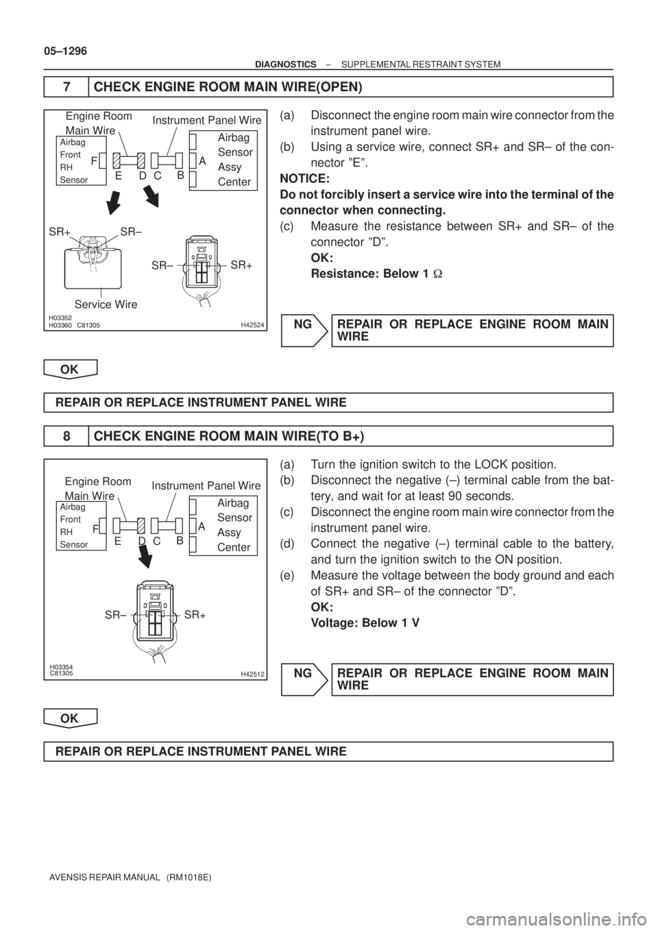
7 CHECK ENGINE ROOM MAIN WIRE(OPEN)
(a) Disconnect the engine room main wire connector from the
instrument panel wire.
(b) Using a service wire, connect SR+ and SR± of the con-
nector ºEº.
NOTICE:
Do not forcibly insert a service wire into the terminal of the
connector when connecting.
(c) Measure the resistance between SR+ and SR± of the
connector ºDº.
OK:
Resistance: Below 1 �
NG REPAIR OR REPLACE ENGINE ROOM MAIN
WIRE
OK
REPAIR OR REPLACE INSTRUMENT PANEL WIRE
8 CHECK ENGINE ROOM MAIN WIRE(TO B+)
(a) Turn the ignition switch to the LOCK position.
(b) Disconnect the negative (±) terminal cable from the bat-
tery, and wait for at least 90 seconds.
(c) Disconnect the engine room main wire connector from the
instrument panel wire.
(d) Connect the negative (±) terminal cable to the battery,
and turn the ignition switch to the ON position.
(e) Measure the voltage between the body ground and each
of SR+ and SR± of the connector ºDº.
OK:
Voltage: Below 1 V
NG REPAIR OR REPLACE ENGINE ROOM MAIN
WIRE
OK
REPAIR OR REPLACE INSTRUMENT PANEL WIRE
Page 1361 of 5135
�����
�����
�����
�����H42837
Airbag
Sensor
Assy
Center Floor Wire
Side
Airbag
Sensor
Assy LH
BBL± BBL+
w/o Curtain
Shield Airbag:w/ Curtain
Shield Airbag:
BCL±
BCL+BBL±
BBL+
A
B
C D
�����
�����
�����
�����H42231
Side
Airbag
Sensor
Assy LHAirbag
Sensor
Assy
Center
BBL±
BBL+Floor Wire
A
B C D
05±1290
± DIAGNOSTICSSUPPLEMENTAL RESTRAINT SYSTEM
AVENSIS REPAIR MANUAL (RM1018E)
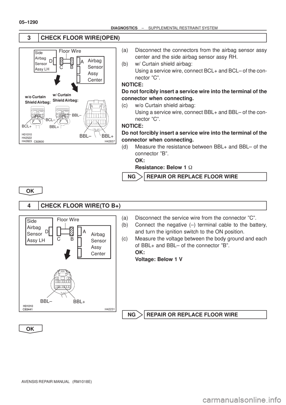
3 CHECK FLOOR WIRE(OPEN)
(a) Disconnect the connectors from the airbag sensor assy
center and the side airbag sensor assy RH.
(b) w/ Curtain shield airbag:
Using a service wire, connect BCL+ and BCL± of the con-
nector ºCº.
NOTICE:
Do not forcibly insert a service wire into the terminal of the
connector when connecting.
(c) w/o Curtain shield airbag:
Using a service wire, connect BBL+ and BBL± of the con-
nector ºCº.
NOTICE:
Do not forcibly insert a service wire into the terminal of the
connector when connecting.
(d) Measure the resistance between BBL+ and BBL± of the
connector ºBº.
OK:
Resistance: Below 1 �
NG REPAIR OR REPLACE FLOOR WIRE
OK
4 CHECK FLOOR WIRE(TO B+)
(a) Disconnect the service wire from the connector ºCº.
(b) Connect the negative (±) terminal cable to the battery,
and turn the ignition switch to the ON position.
(c) Measure the voltage between the body ground and each
of BBL+ and BBL± of the connector ºBº.
OK:
Voltage: Below 1 V
NG REPAIR OR REPLACE FLOOR WIRE
OK
Page 1365 of 5135
�����
�����
�����
�����H42838
Airbag
Sensor
Assy
Center Floor Wire No.2
BBR+
BBR±Side Airbag
Sensor Assy RH
w/o Curtain
Shield Airbag:w/ Curtain
Shield Airbag:
BBR+BBR±
BCR+
BCR±
A
B C D
����� �����
����� �����H42229
Side
Airbag
Sensor
Assy RHAirbag
Sensor
Assy
Center
BBR±
BBR+
Floor Wire No.2
A
B C D
05±1286
± DIAGNOSTICSSUPPLEMENTAL RESTRAINT SYSTEM
AVENSIS REPAIR MANUAL (RM1018E)
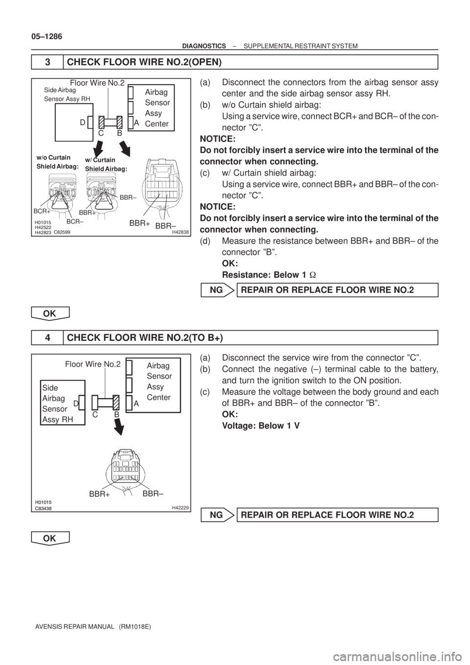
3 CHECK FLOOR WIRE NO.2(OPEN)
(a) Disconnect the connectors from the airbag sensor assy
center and the side airbag sensor assy RH.
(b) w/o Curtain shield airbag:
Using a service wire, connect BCR+ and BCR± of the con-
nector ºCº.
NOTICE:
Do not forcibly insert a service wire into the terminal of the
connector when connecting.
(c) w/ Curtain shield airbag:
Using a service wire, connect BBR+ and BBR± of the con-
nector ºCº.
NOTICE:
Do not forcibly insert a service wire into the terminal of the
connector when connecting.
(d) Measure the resistance between BBR+ and BBR± of the
connector ºBº.
OK:
Resistance: Below 1 �
NG REPAIR OR REPLACE FLOOR WIRE NO.2
OK
4 CHECK FLOOR WIRE NO.2(TO B+)
(a) Disconnect the service wire from the connector ºCº.
(b) Connect the negative (±) terminal cable to the battery,
and turn the ignition switch to the ON position.
(c) Measure the voltage between the body ground and each
of BBR+ and BBR± of the connector ºBº.
OK:
Voltage: Below 1 V
NG REPAIR OR REPLACE FLOOR WIRE NO.2
OK