Page 4690 of 5135

141NB−01
−
ENGINE MECHANICAL CYLINDER HEAD GASKET (2AZ −FSE)
14 −79
AVENSIS Supplement (RM1045E)
REPLACEMENT
1. DISCHARGE FUEL SYSTEM PRESSURE (See page 11 −4)
2. REMOVE FRONT WHEEL RH
3. REMOVE RADIATOR SUPPORT OPENING COVER (See page 14 −23)
4. REMOVE ENGINE ROOM COVER SIDE (See page 14 −23)
5. REMOVE ENGINE UNDER COVER LH (See page 14 −23)
6. REMOVE ENGINE UNDER COVER NO.4 RH (See page 14 −23)
7. REMOVE ENGINE UNDER COVER RH (See page 14 −23)
8. DRAIN COOLANT (See page 16 −7)
9. DRAIN ENGINE OIL (See page 17 −6)
10. REMOVE ENGINE COVER SUB −ASSY NO.1 (See page 14 −45)
11. REMOVE FUEL PRESSURE PULSATION DAMPER ASSY
12. SEPARATE FUEL TUBE SUB −ASSY (See page 11 −4)
13. REMOVE FUEL PIPE SUB −ASSY NO.1 (See page 11 −24)
SST 09023 −12900
14. REMOVE FUEL PUMP ASSY (See page 11 −24)
15. REMOVE FAN AND GENERATOR V BELT (See page 14 −5)
SST 09249 −63010
16. REMOVE GENERATOR ASSY (See page 19 −8)
17. REMOVE EXHAUST PIPE ASSY FRONT (See page 15 −2)
18. SEPARATE VANE PUMP ASSY (See page 14 −45)
19. REMOVE IGNITION COIL ASSY (See page 14 −45)
20. SEPARATE RETURN TUBE SUB −ASSY (See page 14 −45)
21. SEPARATE COOLER REFRIGERANT SUCTION HOSE NO.1 (LHD STEERING POSITION TYPE) (See page 14 −45)
22. REMOVE VANE PUMP OIL RESERVOIR ASSY (See page 14 −45)
23. REMOVE OIL RESERVOIR BRACKET NO.1 (See page 14 −45)
24. SEPARATE ENGINE WIRE (See page 14 −23)
25. REMOVE COOLER BRACKET (LHD STEERING POSITION TYPE) (See page 14 −45)
26. REMOVE ENGINE SERVICE COVER BRACKET RH (RHD STEERING POSITION TYPE)
(See page 14 −45)
27. REMOVE CYLINDER HEAD COVER SUB −ASSY (See page 14 −45)
28. SET NO. 1 CYLINDER TO TDC/COMPRESSION (See page 14 −45)
29. REMOVE ENGINE MOUNTING BRACKET NO.2 RH (See page 14 −45)
30. REMOVE TRANSVERSE ENGINE ENGINE MOUNTING INSULATOR (See page 14 −45)
31. REMOVE CRANKSHAFT PULLEY (See page 14 −45)
SST 09213 −54015 (91651 −60855), 09330 −00021, 09950 −50013 (09951 −05010, 09952 −05010,
09953 −05020, 09954 −05021)
32. REMOVE CHAIN TENSIONER ASSY NO.1 (See page 14 −45)
33. REMOVE CRANKSHAFT POSITION SENSOR (See page 14 −45)
34. REMOVE OIL PAN SUB −ASSY (See page 14 −45)
SST 09032 −00100
35. REMOVE V −RIBBED BELT TENSIONER ASSY (See page 14 −45)
36. REMOVE TIMING CHAIN OR BELT COVER SUB −ASSY (See page 14 −45)
37. REMOVE CRANKSHAFT POSITION SENSOR PLATE NO.1 (See page 14 −45)
38. REMOVE CHAIN TENSIONER SLIPPER (See page 14 −45)
39. REMOVE CHAIN VIBRATION DAMPER NO.1 (See page 14 −45)
40. REMOVE TIMING CHAIN GUIDE (See page 14 −45)
41. REMOVE CHAIN SUB −ASSY (See page 14 −45)
Page 4694 of 5135

A83481
−
ENGINE MECHANICAL CYLINDER HEAD GASKET (2AZ −FSE)
14 −83
AVENSIS Supplement (RM1045E)
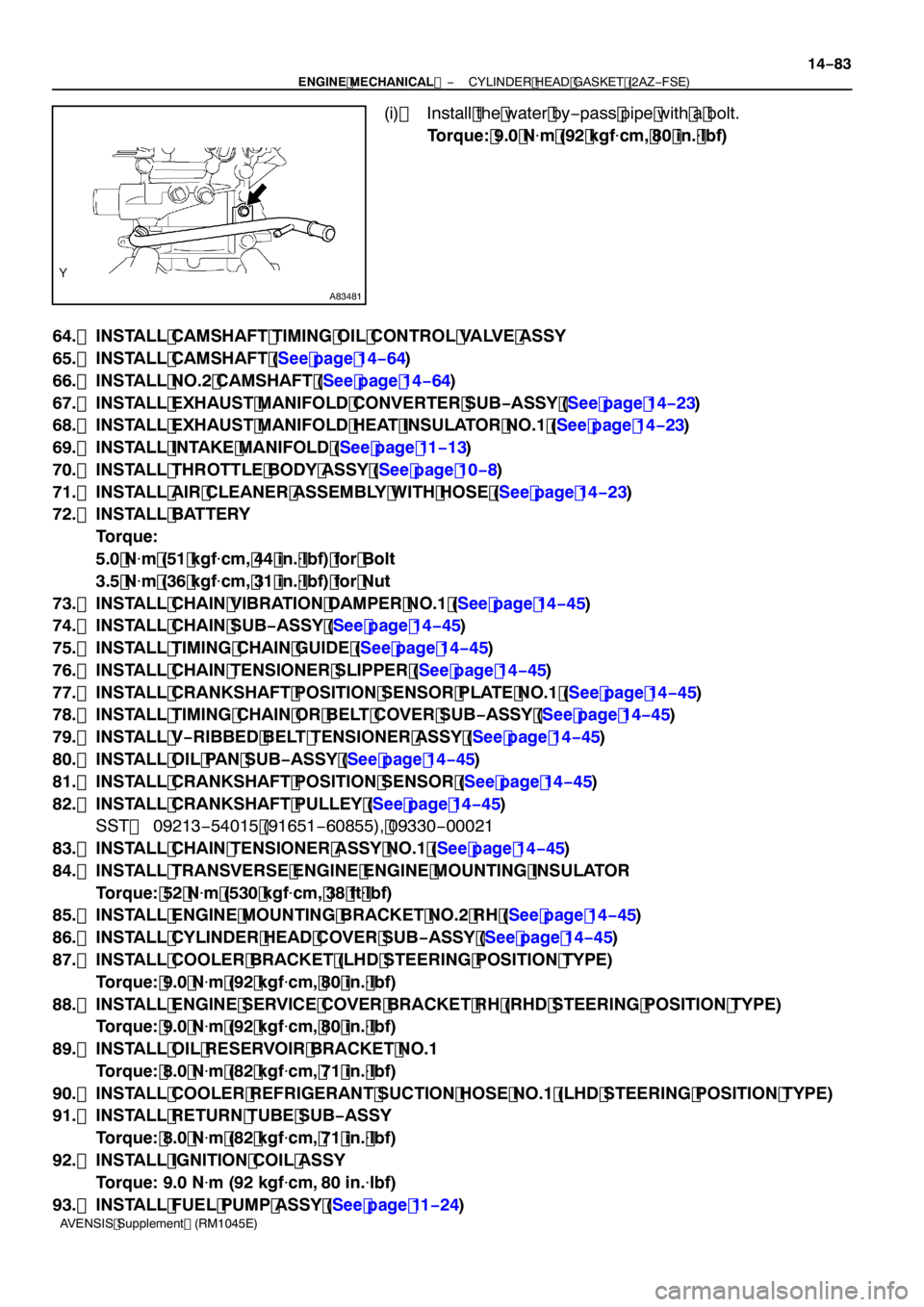
(i) Install the water by −pass pipe with a bolt.
Torque: 9.0 N �m (92 kgf �cm, 80 in. �lbf)
64. INSTALL CAMSHAFT TIMING OIL CONTROL VALVE ASSY
65. INSTALL CAMSHAFT (See page 14 −64)
66. INSTALL NO.2 CAMSHAFT (See page 14 −64)
67. INSTALL EXHAUST MANIFOLD CONVERTER SUB −ASSY (See page 14 −23)
68. INSTALL EXHAUST MANIFOLD HEAT INSULATOR NO.1 (See page 14 −23)
69. INSTALL INTAKE MANIFOLD (See page 11 −13)
70. INSTALL THROTTLE BODY ASSY (See page 10 −8)
71. INSTALL AIR CLEANER ASSEMBLY WITH HOSE (See page 14 −23)
72. INSTALL BATTERY
Torque:
5.0 N�m (51 kgf �cm, 44 in. �lbf) for Bolt
3.5 N �m (36 kgf �cm, 31 in. �lbf) for Nut
73. INSTALL CHAIN VIBRATION DAMPER NO.1 (See page 14 −45)
74. INSTALL CHAIN SUB −ASSY (See page 14 −45)
75. INSTALL TIMING CHAIN GUIDE (See page 14 −45)
76. INSTALL CHAIN TENSIONER SLIPPER (See page 14 −45)
77. INSTALL CRANKSHAFT POSITION SENSOR PLATE NO.1 (See page 14 −45)
78. INSTALL TIMING CHAIN OR BELT COVER SUB −ASSY (See page 14 −45)
79. INSTALL V −RIBBED BELT TENSIONER ASSY (See page 14 −45)
80. INSTALL OIL PAN SUB −ASSY (See page 14 −45)
81. INSTALL CRANKSHAFT POSITION SENSOR (See page 14 −45)
82. INSTALL CRANKSHAFT PULLEY (See page 14 −45)
SST 09213 −54015 (91651 −60855), 09330 −00021
83. INSTALL CHAIN TENSIONER ASSY NO.1 (See page 14 −45)
84. INSTALL TRANSVERSE ENGINE ENGINE MOUNTING INSULATOR
Torque: 52 N �m (530 kgf �cm, 38 ft �lbf)
85. INSTALL ENGINE MOUNTING BRACKET NO.2 RH (See page 14 −45)
86. INSTALL CYLINDER HEAD COVER SUB −ASSY (See page 14 −45)
87. INSTALL COOLER BRACKET (LHD STEERING POSITION TYPE)
Torque: 9.0 N �m (92 kgf �cm, 80 in. �lbf)
88. INSTALL ENGINE SERVICE COVER BRACKET RH (RHD STEERING POSITION TYPE) Torque: 9.0 N �m (92 kgf �cm, 80 in. �lbf)
89. INSTALL OIL RESERVOIR BRACKET NO.1 Torque: 8.0 N �m (82 kgf �cm, 71 in. �lbf)
90. INSTALL COOLER REFRIGERANT SUCTION HOSE NO.1 (LHD STEERING POSITION TYPE)
91. INSTALL RETURN TUBE SUB −ASSY
Torque: 8.0 N �m (82 kgf �cm, 71 in. �lbf)
92. INSTALL IGNITION COIL ASSY
Torque: 9.0 N �m (92 kgf �cm, 80 in. �lbf)
93. INSTALL FUEL PUMP ASSY (See page 11 −24)
Page 4766 of 5135

I35328
(1)(2)
(3)
(4)
−
HEATER & AIR CONDITIONER W/PULLEY COMPRESSOR ASSY (2AZ −FSE)
55 −5
AVENSIS Supplement (RM1045E)
9. INSPECT COMPRESSOR OIL
(a) When replacing the w/pulley compressor assy with a new one, after gradually removing the refrigerant
gas from the service valve, drain the following amount of oil from the new w/pulley compressor assy
before installation.
Standard:
(Oil capacity inside new w/pulley compressor assy: 90 + 15 cc (3.0 + 0.5 fl. oz.) ) − (Remaining
oil amount in the removed w/pulley compressor assy) = (Oil amount to be removed when replac-
ing)
NOTICE:
S When checking the compressor oil level, observe the precautions on the cooler removal/instal-
lation.
S Since compressor oil remains in the pipes of the vehicle, if a new w/pulley compressor assy
is installed without removing some oil inside, the oil amount becomes excessive, preventing
heat exchange in the refrigerant cycle and causing refrigerant failure.
S If the remaining oil in the removed w/pulley compressor assy is too small in volume, check for
oil leakage.
S Be sure to use ND −OIL 8 for compressor oil.
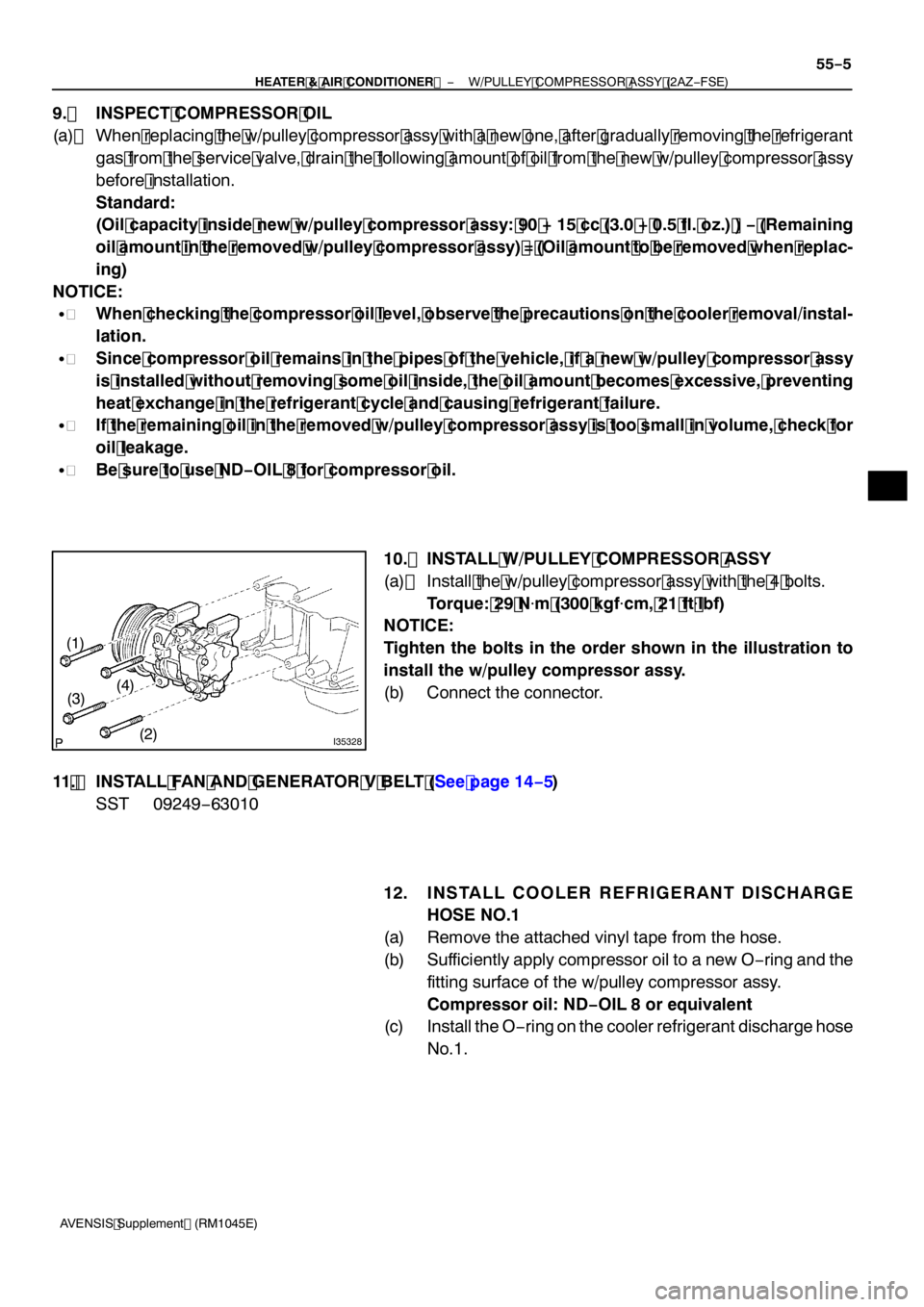
10. INSTALL W/PULLEY COMPRESSOR ASSY
(a) Install the w/pulley compressor assy with the 4 bolts.
Torque: 29 N �m (300 kgf �cm, 2 1 ft �lbf)
NOTICE:
Tighten the bolts in the order shown in the illustration to
install the w/pulley compressor assy.
(b) Connect the connector.
11 . INSTALL FAN AND GENERATOR V BELT (See page 14− 5)
SST 09249 −63010
12. INSTALL COOLER REFRIGERANT DISCHARGE
HOSE NO. 1
(a) Remove the attached vinyl tape from the hose.
(b) Sufficiently apply compressor oil to a new O −ring and the
fitting surface of the w/pulley compressor assy.
Compressor oil: ND −OIL 8 or equivalent
(c) Install the O −ring on the cooler refrigerant discharge hose
No.1.
Page 5012 of 5135

05KYC–01
F40034DLC3
12 3 4567 8 12 3 4567 8
9 1011 12131415 16
05–306– DIAGNOSTICSCRUISE CONTROL SYSTEM (2AZ–FSE)(From
February, 2004)
AVENSIS REPAIR MANUAL SUPPLEMENT
(RM1098E)
PRE–CHECK
1. DIAGNOSIS SYSTEM
(a) Description
The ECM stores trouble codes when trouble occurs on
the vehicle.
The diagnosis system allows for reading of the trouble
codes from the DLC3. If the CRUISE main indicator light
does not come on after DTC check, it means a malfunc-
tion has occurred in the cruise control system.
Use the intelligent tester II to check and solve the prob-
lem.
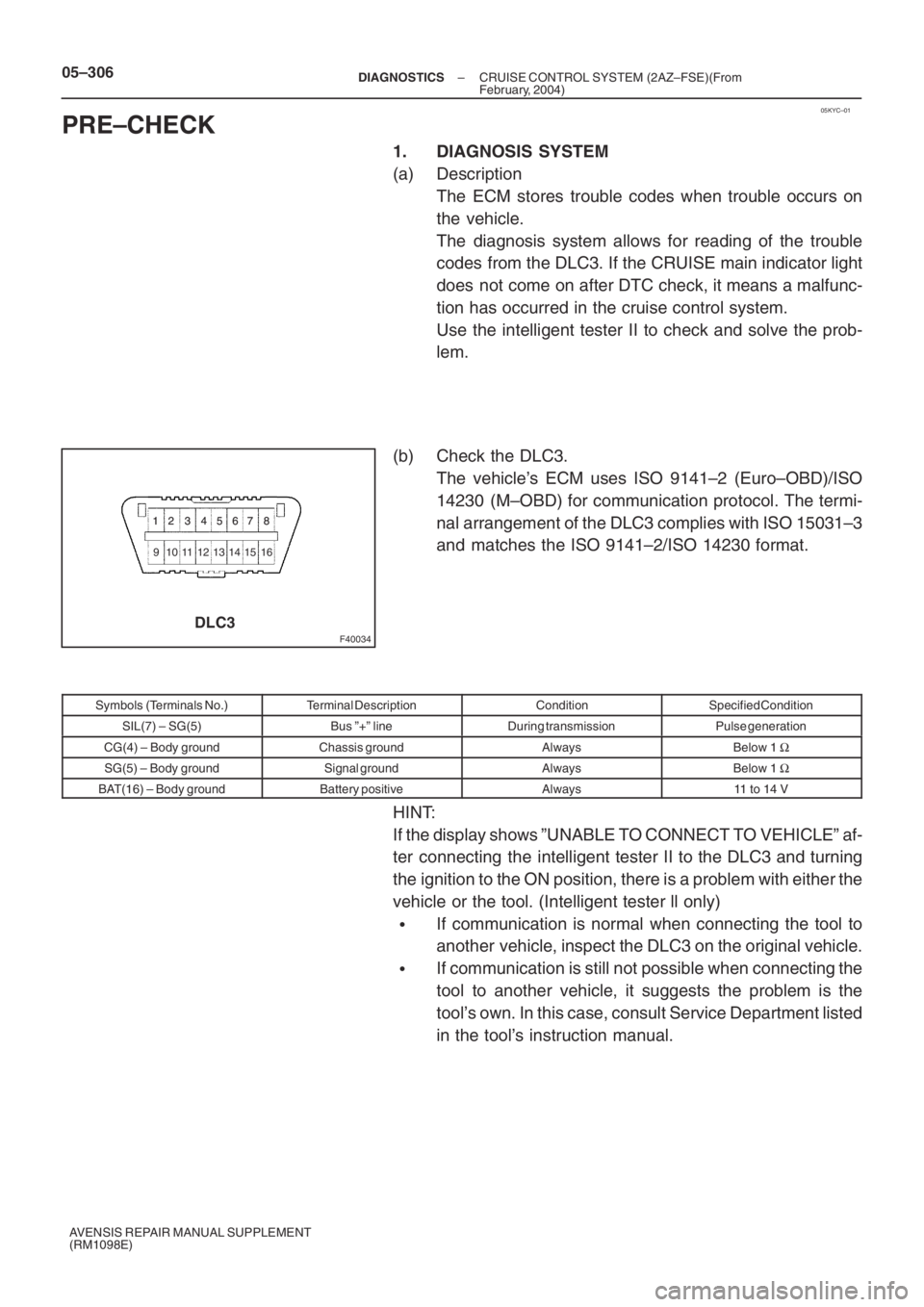
(b) Check the DLC3.
The vehicle’s ECM uses ISO 9141–2 (Euro–OBD)/ISO
14230 (M–OBD) for communication protocol. The termi-
nal arrangement of the DLC3 complies with ISO 15031–3
and matches the ISO 9141–2/ISO 14230 format.
Symbols (Terminals No.)Terminal DescriptionConditionSpecified Condition
SIL(7) – SG(5)Bus ”+” lineDuring transmissionPulse generation
CG(4) – Body groundChassis groundAlwaysBelow 1 Ω
SG(5) – Body groundSignal groundAlwaysBelow 1 Ω
BAT(16) – Body groundBattery positiveAlways11 to 14 V
HINT:
If the display shows ”UNABLE TO CONNECT TO VEHICLE” af-
ter connecting the intelligent tester II to the DLC3 and turning
the ignition to the ON position, there is a problem with either the
vehicle or the tool. (Intelligent tester ll only)
�If communication is normal when connecting the tool to
another vehicle, inspect the DLC3 on the original vehicle.
�If communication is still not possible when connecting the
tool to another vehicle, it suggests the problem is the
tool’s own. In this case, consult Service Department listed
in the tool’s instruction manual.